
Subscribe to Our Youtube Channel
Related Manuals for Woodward Flo-Tech 8400-511


Summary of Contents for Woodward Flo-Tech 8400-511
- Page 1 Hardware Manual Digital Min/Max Flo-Tech™ Control 8400-511 for Cummins Jade/Bravo Engines Manual 04168...
- Page 2 Protection of Electronic Controls, Printed Circuit Boards, and Modules. Woodward Governor Company reserves the right to update any portion of this publication at any time. Information provided by Woodward Governor Company is believed to be correct and reliable. However, no responsibility is assumed by Woodward Governor Company unless otherwise expressly undertaken.
-
Page 3: Table Of Contents
Figure 1-2. Digital Min/Max Flo-Tech Control Box ..........3 Figure 1-3. Typical Flo-Tech Outline Drawing ............4 Figure 1-4. Network Connection Example .............. 5 Figure 1-5a. Plant Wiring Diagram ................. 6 Figure 1-5b. Plant Wiring Diagram ................. 7 Woodward... -
Page 4: Electrostatic Discharge Awareness
PCB from the control cabinet, place it in the antistatic protective bag. To prevent damage to electronic components caused by improper handling, read and observe the precautions in Woodward manual 82715, Guide for Handling and Protection of Electronic Controls, Printed Circuit Boards, and Modules. -
Page 5: Chapter 1. General Information
Failure to properly install and operate the control system could result in possible personal injury or loss of life. This hardware manual describes the capabilities of the Woodward Digital Min/Max Flo-Tech™ control, model 8400-511, for Cummins Jade/Bravo engines. Application The Woodward Digital Min/Max Flo-Tech control (DMMF) permits efficient idle, fast-idle, and maximum engine-speed control of spark-ignited gas engines. -
Page 6: Figure 1-1. Typical System Layout
Digital Min/Max Flo-Tech Control Manual 04168 Figure 1-1. Typical System Layout Woodward... -
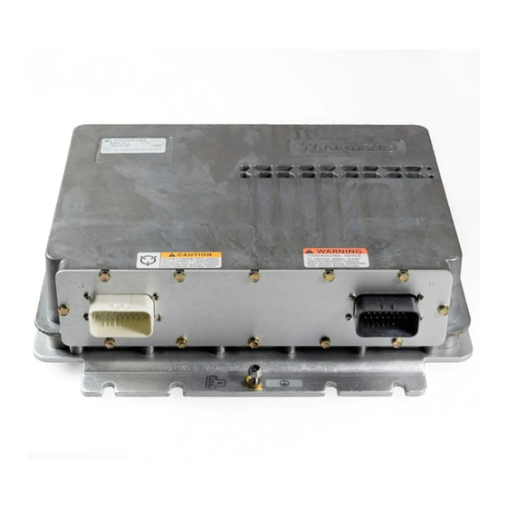
Page 7: Figure 1-2. Digital Min/Max Flo-Tech Control Box
Manual 04168 Digital Min/Max Flo-Tech Control Figure 1-2. Digital Min/Max Flo-Tech Control Box Woodward... -
Page 8: Figure 1-3. Typical Flo-Tech Outline Drawing
Digital Min/Max Flo-Tech Control Manual 04168 Figure 1-3. Typical Flo-Tech Outline Drawing Woodward... -
Page 9: Figure 1-4. Network Connection Example
Manual 04168 Digital Min/Max Flo-Tech Control Figure 1-4. Network Connection Example Woodward... -
Page 10: Figure 1-5A. Plant Wiring Diagram
Digital Min/Max Flo-Tech Control Manual 04168 Figure 1-5a. Plant Wiring Diagram Woodward... -
Page 11: Figure 1-5B. Plant Wiring Diagram
Manual 04168 Digital Min/Max Flo-Tech Control Figure 1-5b. Plant Wiring Diagram Woodward... -
Page 12: Chapter 2. Installation
Ideally, the control should be mounted flush to the metal side of a control cabinet close to the engine. The location should provide protection from high-voltage or high-current devices, or devices which produce electromagnetic interference. Do not install the control box directly on the engine. Woodward... -
Page 13: Mounting The Flo-Tech Actuator/Throttle Body
Connectors The DMMF interfaces to the engine and vehicle systems through two 23-pin AMP connectors. The Woodward part numbers for these parts as well as the actuator connector part number(s) are located on the plant wiring diagram (Figure 1-5). The part numbers also list the pins required for the 23-pin DMMF connector. - Page 14 50 mm (2 inches). The other end of the shields must be left open and insulated from any other conductor. DO NOT run shielded signal wires along with other wires carrying large currents. See Woodward application note 50532, Interference Control in Electronic Governing Systems, for more information.
-
Page 15: Chapter 3. Description Of Operation
The Flo-Tech 60 requires no actuators or linkage. The Flo-Tech 60 will accept an 8–32 Vdc (12/24 Vdc nominal) input power supply and a positioning command signal. The driver will produce an output signal to indicate throttle position. Woodward... -
Page 16: Return Spring
Digital Min/Max Flo-Tech Control Manual 04168 The Flo-Tech 60 is configured to work with a command signal of 0–5 Vdc. Woodward part numbers for the DMMF Flo-Tech are: • 8235-113—Jade • 8235-123—Bravo Return Spring The Flo-Tech actuator has an internal return spring designed to move the actuator toward minimum fuel in case the electronic control should fail. - Page 17 Resume is desired. Transmission Signal Output This voltage output sends an analog signal that represents a conditioned throttle position to an automatic transmission that accepts a programmable voltage input between 0 and 6 Vdc (forward or reverse acting). Woodward...
- Page 18 Each set of dynamics provides different gain mapping, stability, compensation, gain ratio, and gain window settings. This allows precise engine control from low idle no load to max speed full load. Woodward...
-
Page 19: Chapter 4. Service Options
Chapter 4. Service Options General The user of the Woodward Digital Min/Max Flo-Tech system should contact your Cummins distributor in the local area regarding repairs or returns. Your Cummins distributor handles repairs, replacements, and warranties, and handles sending the control through Cummins Engine Company to Woodward. -
Page 20: Appendix . Dmmf Specifications
Typical Control Characteristics Inputs Power Supply 8 to 32 Vdc (12/24 Vdc nominal) Position Command 0–5 Vdc, 4–20 mA, 0–200 mA, or PWM (greater than 300 Hz, 5% to 95% duty cycle) Outputs Proportional Indication Signal 0–5 Vdc Nominal Woodward... - Page 21 Input Type: contact input Input Impedance: greater than 1 kΩ Contact Input Response time: 50 ms ±25% Min Input High Voltage: 8 Vdc Connections: J2-5, through dash mounted momentary switch to battery (+) (typically). Multiplexed with Cruise Control Set switch. Woodward...
- Page 22 Clutch/Brake Switch Input Type: contact input Input Impedance: greater than 1 kΩ Contact Input Response time: 50 ms ±25% Min Input High Voltage: 8 Vdc Connections: J2-11, through normally-closed clutch and brake switches in series to battery (+) (typically) Woodward...
- Page 23 I/O Parameter: Cruise Control Resume Switch Input Type: contact input Input Impedance: greater than 1 kΩ Contact Input Response time: 50 ms ±25% Min Input High Voltage: 8 Vdc Connections: J2-6, through dash mounted momentary switch to battery (+) (typically). Woodward...
- Page 24 Email and Website—www.woodward.com Woodward has company-owned plants, subsidiaries, and branches, as well as authorized distributors and other authorized service and sales facilities throughout the world. Complete address / phone / fax / email information for all locations is available on our website.
Need help?
Do you have a question about the Flo-Tech 8400-511 and is the answer not in the manual?
Questions and answers