
Related Manuals for Woodward 2300E


Summary of Contents for Woodward 2300E
- Page 1 Product Manual 26691 (Revision E, 7/2016) Original Instructions 2300E Digital Load Sharing and Speed Control for Engines 8273-1017 / Ordinary Locations 8273-1018 / Hazardous Locations Installation and Operation Manual...
- Page 2 Revisions—Changes in this publication since the last revision are indicated by a black line alongside the text. Woodward reserves the right to update any portion of this publication at any time. Information provided by Woodward is believed to be correct and reliable. However, no responsibility is assumed by Woodward unless otherwise expressly undertaken.
-
Page 3: Table Of Contents
Product Support Options ..................27 Product Service Options ..................27 Returning Equipment for Repair ................28 Replacement Parts ....................28 Engineering Services .................... 29 Contacting Woodward’s Support Organization ............ 29 Technical Assistance .................... 30 A. 2300E C ........31 PPENDIX... - Page 4 Figure 1-1a. 2300E Outline Drawing (Ordinary Locations) ........3 Figure 1-1b. 2300E Outline Drawing (Hazardous Locations) ......... 4 Figure 1-2a. 2300E Control Wiring Diagram (sheet 1) ........... 5 Figure 1-2b. 2300E Control Wiring Diagram (sheet 2) ........... 6 Figure 1-2c. 2300E Control Wiring Diagram (notes) ..........7 Figure 2-1.
-
Page 5: Warnings And Notices
Start-up On- and off-highway Mobile Applications: Unless Woodward's control functions as the supervisory control, customer should install a system totally independent of the prime mover control system that... -
Page 6: Electrostatic Discharge Awareness
Do not touch the components or conductors on a printed circuit board with your hands or with conductive devices. To prevent damage to electronic components caused by improper handling, read and observe the precautions in Woodward manual 82715 , Guide for Handling and Protection of Electronic Controls, Printed Circuit Boards, and Modules. -
Page 7: Regulatory Compliance
Manual 26691 2300E Digital Control Regulatory Compliance European Compliance for CE Mark These listings are limited only to those units bearing the CE Marking. Low Voltage Directive: Directive 2014/35/EU on the harmonisation of the laws of the Member States relating to the making available on the... - Page 8 2300E Digital Control Manual 26691 Lloyd’s Register LR Type Approval Test Specification No. 1, 2002 for of Shipping: Shipping: Environmental Categories ENV1, ENV2 and ENV3 Nippon Kaiji Kyokai: Requirements specified in Chapter 1, Part 7 of Guidance for the approval and Type Approval of materials and equipment for Marine use and relevant Society’s Rules.
-
Page 9: Chapter 1. General Information
4 Discrete (Relay Driver) Outputs 2 Serial Ports 1 CAN Port The following is an example of the typical hardware needed for a 2300E system controlling a single prime mover and generator: A 2300E electronic control ... -
Page 10: References
2300E Digital Control Manual 26691 The frequency from the magnetic pickup must be within the range of 100 to 25 000 Hz at rated speed. The 2300E speed range needs to be configured using an external computer during installation. References The following publications contain additional product or installation information on Load Sharing and Speed Controls, and related components. -
Page 11: Figure 1-1A. 2300E Outline Drawing (Ordinary Locations)
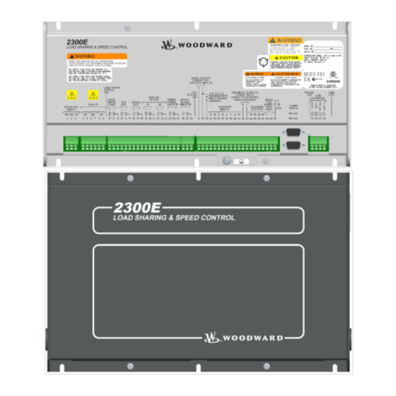
Manual 26691 2300E Digital Control Figure 1-1a. 2300E Outline Drawing (Ordinary Locations) Woodward... -
Page 12: Figure 1-1B. 2300E Outline Drawing (Hazardous Locations)
2300E Digital Control Manual 26691 Figure 1-1b. 2300E Outline Drawing (Hazardous Locations) Woodward... -
Page 13: Figure 1-2A. 2300E Control Wiring Diagram (Sheet 1)
4 5 - 6 6 HZ T O V OL T MET ER, ET C POT ENT I AL ON SWI T CHBOARD V OL T AGE MAI N GENERAT OR CI RCUI T BREAKER Figure 1-2a. 2300E Control Wiring Diagram (sheet 1) Woodward... -
Page 14: Figure 1-2B. 2300E Control Wiring Diagram (Sheet 2)
J UMPER I F USI NG I NT ERNAL POWER F OR DI SCRET E I NPUT S 2 4 V DC OUT PUT POWER F OR DI SCRET E I NPUT S Figure 1-2b. 2300E Control Wiring Diagram (sheet 2) Woodward... -
Page 15: Figure 1-2C. 2300E Control Wiring Diagram (Notes)
I NST AL L ED I N PL ACE OF MET ERS SHOWN. I NDI CAT ES REL AY COI L OR L AMP, 2 00 mA MAXI MUM PER CHANNEL . OPT I ONAL SEE BOM Figure 1-2c. 2300E Control Wiring Diagram (notes) Woodward... -
Page 16: Chapter 2. Installation
ESD bag, at least until it is grounded. Power Requirements The 2300E control requires a voltage source of 18 to 36 Vdc, with a current capacity of at least 600 mA for operating power. If a battery is used for operating power, an alternator or other battery charging device is necessary to maintain a stable supply voltage. -
Page 17: Location Considerations
For example, relay contact wiring and electric motor drive or ignition system wiring should be at least 30 cm (12 inches) from any 2300E wiring. And for example, analog inputs/output wiring should be separated from power wiring by at least 15 cm (6 inches). -
Page 18: Shields And Grounding
(exception, see note below on cabinet installations). Shields can be grounded at both ends (2300E and load) if the cable length is sufficiently short (i.e., within a cabinet, less than about 10 m straight line between the ground points) to prevent ground loop current in the shield. -
Page 19: Potential Transformer Connections (Terminals 1-3)
The control uses the equation Power = 3 * V * I * P.F. where V = Voltage, I = current, and P.F. = Power Factor. In the 2300E, the PT Voltage part of the equation is deemed to be constant. Therefore if the Voltage on the system changes, the calculated Power will change a small amount. -
Page 20: Power Supply (Terminals 48-50)
PT/CT circuits. Discrete Inputs (Terminals 34–41) Discrete inputs are the switch or contact input commands to the 2300E control. They interact in such a way as to allow engine control and power management under a variety of conditions. -
Page 21: Actuator Output (Terminals 13-15)
Manual 26691 2300E Digital Control In systems that provide an external low voltage source to power the 2300E control, the discrete inputs may be powered by this external low voltage. The voltage source used must be capable of supplying 100 mA at a voltage level of 18 to 36 Vdc. -
Page 22: Speed Sensor (Terminals 25-30)
+12 Vdc or +24 Vdc source connected at terminals 42(+) and 43(–). The Relay Driver Output pins are: #1(44), #2(43), #3(46), and #4(47). The relay driver section is isolated from the internal power supplies of the 2300E control, but all drivers share a single common. -
Page 23: Communication Ports
These ports are on a common return and are isolated ports. The RS-232 serial communication service port communicates using either the 2300E Toolkit Service Tool or the Control Assistant software. Refer to Figure 2-2 for plant wiring information. -
Page 24: Figure 2-3. Typical Rs-422 Communications Connections
The RS-422 specifications state that a common/RS-422 ground wire is needed if there is no other ground path between units. The RS-422 on the 2300E is isolated, so there is no other path for common other than wiring to the pin. -
Page 25: Figure 2-5. Preferred Multipoint Wiring Using Shielded Twisted-Pair Cable With A Separate Signal Ground Wire
Manual 26691 2300E Digital Control If the total cabling is > 30 m (typical), the preferred shield connection is to connect the shield to earth ground (chassis) at one point (most critical port), using a capacitor to terminate the shield at the remaining ports. If the total cabling is <... -
Page 26: Can Communication Port (Terminals 51-54)
The CAN Port is electrically isolated from all other circuits in the 2300E, requiring a common to be wired between this port and other ports on the CAN network. - Page 27 Also, both the “thick” and “thin” DeviceNet cables have wire insulation and wire size that is not compatible with the 2300E connectors. When using DeviceNet cables outside a vibration damped enclosure, use the “Thick”...
-
Page 28: Figure 2-7. Can Cable Cross-Section
The next best alternative is to use a very short drop line from the trunk into the 2300E. Special ‘T’ connectors (Tap in the diagram above) are available from multiple manufacturers to ease the wiring harness manufacture. -
Page 29: Figure 2-8. Can System Wiring Example
In order to allow the possibility of removing and inserting a unit onto a running network, the CAN termination network is not included inside the 2300E control. An external CAN termination network must be provided. As a rule, no matter how many units are on a network, there should never be more than two network terminations installed. - Page 30 CAN Port Wiring The CAN Port may be used for off-engine wiring to control rooms. It is electrically isolated from all other circuits in the 2300E. Isolation used on this port is SELV rated for product safety requirements. Wiring length restrictions depend on the baud rate used. Table 2-3 is appropriate for CANopen, at the 4 supported baud rates.
-
Page 31: Installation Check-Out Procedure
Manual 26691 2300E Digital Control Installation Check-out Procedure With the installation completed as described in this section, perform the following check-out procedure. Visual Inspection 1. Check the linkage between the actuator and the prime mover for looseness or binding. Refer to the appropriate actuator manual and to manual 25070, Electric Governor Installation Guide, for additional information on the linkage. -
Page 32: Gap Software And Communication Procedures
GAP Software Woodward’s GAP 3.x is a Windows based software program that allows controls engineers to create block format application programs for the 2300E. Once the control logic is entered using the program’s graphical programming environment, the GAP software compiler function generates code that runs in the control. - Page 33 RAM of 45 Kbytes, leaving about 35 Kbytes. A suggestion when programming the 2300E would be to not use all of the Rate Groups available. In the Standard 2301E application, only two rate groups were used 5 mSec and 80 mSec.
-
Page 34: Control Assistant Pc Interface
Woodward Control Assistant or Servlink OPC Server can be used to download a new application GAP compiled program into the 2300E. The 2300E default baud rate is 115200, which can be entered in the SOS Servlink OPC Server window or it will automatically detect the correct baud rate. -
Page 35: Chapter 4. Product Support And Service Options
A current list of Woodward Business Partners is available at www.woodward.com/directory. Product Service Options Depending on the type of product, the following options for servicing Woodward products may be available through your local Full-Service Distributor or the OEM or Packager of the equipment system. -
Page 36: Returning Equipment For Repair
To prevent damage to electronic components caused by improper handling, read and observe the precautions in Woodward manual 82715, Guide for Handling and Protection of Electronic Controls, Printed Circuit Boards, and Modules. -
Page 37: Engineering Services
Field Service engineering on-site support is available, depending on the product and location, from one of our Full-Service Distributors. The field engineers are experienced both on Woodward products as well as on much of the non- Woodward equipment with which our products interface. -
Page 38: Technical Assistance
Manual 26691 Technical Assistance If you need to contact technical assistance, you will need to provide the following information. Please write it down here before contacting the Engine OEM, the Packager, a Woodward Business Partner, or the Woodward factory: General... -
Page 39: 2300E Control Specifications
Manual 26691 2300E Digital Control Appendix A. 2300E Control Specifications Woodward Part Numbers: 8273-1011 2300E Load Sharing and Speed Control, 24 Vdc input, Ordinary Locations 8273-1012 2300E Load Sharing and Speed Control, 24 Vdc input, Hazardous Locations 8928-5014 Control Assistant... -
Page 40: Revision History
Updated Regulatory Compliance section Revised Declaration of Conformity Changes in Revision D— Added information clarifying the memory structure of the 2300E. Revise Australia and New Zealand compliance information Changes in Revision C— Corrected 3-phase PT Burden in Specifications section to 90–240 Vac line- to-line, 45–66 Hz... -
Page 41: Declarations
Manual 26691 2300E Digital Control Declarations Woodward... - Page 42 Email and Website—www.woodward.com Woodward has company-owned plants, subsidiaries, and branches, as well as authorized distributors and other authorized service and sales facilities throughout the world. Complete address / phone / fax / email information for all locations is available on our website.
Need help?
Do you have a question about the 2300E and is the answer not in the manual?
Questions and answers