
Subscribe to Our Youtube Channel
Related Manuals for Woodward DSLC


Summary of Contents for Woodward DSLC
- Page 1 Installation and Operation Manual DSLC™ Digital Synchronizer and Load Control Manual 02007 (Revision D)
- Page 2 Revisions—Text changes are indicated by a black line alongside the text. Woodward Governor Company reserves the right to update any portion of this publication at any time. Information provided by Woodward Governor Company is believed to be correct and reliable. However, no responsibility is assumed by Woodward Governor Company unless otherwise expressly undertaken.
-
Page 3: Table Of Contents
Manual 02007 DSLC Digital Synchronizer and Load Control Contents ..........LECTROSTATIC ISCHARGE WARENESS 1. G ............1 HAPTER ENERAL NFORMATION Introduction ......................1 Application ......................1 Synchronizer ......................1 Load Control ......................2 Process Control (full function models) ..............3 ... - Page 4 DSLC Digital Synchronizer and Load Control Manual 02007 Contents 6. VAR/P ....... 76 HAPTER OWER ACTOR ONTROL ESCRIPTION Introduction ......................76 VAR Control ......................76 Power Factor Control ....................76 Power Factor Sharing ...................77 7. P .......... 78 HAPTER...
- Page 5 Figure 1-4. Control Options .................. 11 Figure 2-1. Temporary Wiring for Transformer Phase Correction ....... 15 Figure 2-2. DSLC Control in a Parallel Bus/Utility Parallel Application ....19 Figure 3-1. Hand Held Programmer Functions ............ 22 Figure 4-1. Synchronizer Block Diagram ............. 61 Figure 4-2.
-
Page 6: Electrostatic Discharge Awareness
PCB from the control cabinet, place it in the antistatic protective bag. CAUTION—ELECTROSTATIC DISCHARGE To prevent damage to electronic components caused by improper handling, read and observe the precautions in Woodward manual 82715, Guide for Handling and Protection of Electronic Controls, Printed Circuit Boards, and Modules. Woodward... -
Page 7: Chapter 1. General Information
• Reverse power relay. Synchronizer The DSLC control uses digital signal processing techniques to derive both true RMS voltages and relative phase of the fundamental frequencies of the bus and generator voltage wave forms. Digital signal processing techniques offer significantly improved measurement accuracy in the presence of wave form distortions, particularly since the phase measurement does not depend on zero crossings of the wave forms. -
Page 8: Load Control
The integrating base load control provides accurate load control when in parallel with a bus where frequency may vary. The DSLC control provides switch inputs to allow raising or lowering the internal digital base load reference. The control also provides a 4–20 mA (or 1–5 Vdc) analog input for remote load setting, if desired. -
Page 9: Process Control (Full Function Models)
When unloading from the process control, an adjustable unload ramp provides time controlled unloading to the unload trip level. When load reaches the unload trip level, the DSLC control automatically issues a breaker open command to remove the generator set from the system. The ramp pause switch input allows holding of the unload ramp for cool-down or other purposes. -
Page 10: Manual Organization
DSLC Digital Synchronizer and Load Control Manual 02007 The DSLC control has a selectable voltage range alarm which is activated if the analog output to the voltage regulator reaches high or low saturation. The DSLC control also has selectable and adjustable high and low voltage limit switches and alarm outputs. -
Page 11: Figure 1-1A. Dslc Control (Wye Version Shown)
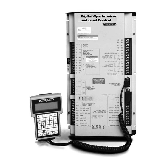
Manual 02007 DSLC Digital Synchronizer and Load Control Figure 1-1a. DSLC Control (wye version shown) Woodward... -
Page 12: Figure 1-1B. Dslc Control Dimensions (Wye Version Shown)
DSLC Digital Synchronizer and Load Control Manual 02007 Figure 1-1b. DSLC Control Dimensions (wye version shown) Woodward... -
Page 13: Figure 1-2. Hand Held Programmer
Manual 02007 DSLC Digital Synchronizer and Load Control Figure 1-2. Hand Held Programmer Woodward... -
Page 14: Figure 1-3A. Dslc Plant Wiring Diagram
DSLC Digital Synchronizer and Load Control Manual 02007 Figure 1-3a. DSLC Plant Wiring Diagram (for 120/240 V wye switch gear configurations) Woodward... -
Page 15: Figure 1-3B. Dslc Plant Wiring Diagram
Manual 02007 DSLC Digital Synchronizer and Load Control Figure 1-3b. DSLC Plant Wiring Diagram (for 120 V open delta switch gear configurations) Woodward... -
Page 16: Figure 1-3C. Dslc Plant Wiring Diagram
DSLC Digital Synchronizer and Load Control Manual 02007 Figure 1-3c. DSLC Plant Wiring Diagram (for 240 V open delta switch gear configurations) Woodward... -
Page 17: Figure 1-4. Control Options
Manual 02007 DSLC Digital Synchronizer and Load Control Figure 1-4. Control Options Woodward... -
Page 18: Chapter 2. Installation
Protect the unit from direct exposure to water or to a condensation-prone environment. • The continuous operating range of the DSLC control is –40 to +70 °C (–40 to +158 °F). • Provide adequate ventilation for cooling. Shield the unit from radiant heat sources. -
Page 19: Shielded Wiring
Contact Woodward for more information. Power Supply The DSLC control requires a nominal voltage source of 18 to 40 Vdc, 18 W. Power to the control should be maintained whenever the generator set is available for service. -
Page 20: Bus Potential Transformers
Figure 1-3 for generator potential transformer wiring. Generator Current Transformers The generator current inputs on the DSLC control are connected to the output of current transformers, which in turn is placed around one conductor of one phase of the generator circuit being monitored. -
Page 21: Discrete Outputs
Figure 2-1. Discrete Outputs The discrete outputs are the relay driver output commands from the DSLC control. Each optically isolated discrete output is designed as a low side driver capable of sinking a maximum of 200 mA. The use of drivers allows the user to supply relays of a contact rating appropriate for the application. -
Page 22: Discrete Inputs
Connect circuit breaker auxiliary (CB Aux) contacts that open and close when the generator breaker opens and closes. Wire the breaker auxiliary contacts in series between the +24 Vdc voltage source and terminal 47 of the DSLC control. Wire an isochronous/droop switch in series with the circuit breaker auxiliary contacts if both isochronous and droop operation are required (closed for isochronous and open for droop;... - Page 23 Wire the voltage raise and lower switch contacts in series between the +24 Vdc voltage source and terminals 48 and 49 of the DSLC control. If a separate switch to enable the VAR/PF control is installed, wire a double-pole, double-throw...
-
Page 24: Lonworks ® Network
Intermediate nodes should not have the termination jumper installed. Speed Control Output Make connections to the DSLC control terminals as shown in Figure 1-3. Connect the cable shields to ground at the speed control end only. Connect to the aux input on speed controls or the load sharing line input on load sharing and speed controls. -
Page 25: Process Control Input
Figure 1-3. For a 4–20 mA transmitter, a jumper must be installed across terminals 37 and 38. For a 1–5 Vdc transmitter, the jumper should not be installed. Connect the cable shields to ground at the DSLC control end only. Remote Load Setting Input To avoid ground loop problems and resulting poor control performance, the remote load setting transmitter should have an isolated output. -
Page 26: Installation Checkout Procedure
DSLC Digital Synchronizer and Load Control Manual 02007 Installation Checkout Procedure When the installation is complete as described in this chapter, do the following checkout procedure before beginning the calibration and adjustments in the next chapter. Check for correct wiring in accordance with the wiring diagram, Figure 1-3. -
Page 27: Chapter 3. Calibration And Adjustment
Introduction Because of the variety of installations, plus system and component tolerances, the DSLC™ control must be tuned to each system for optimum performance. This chapter contains information on control calibration. It includes initial prestart-up and start-up settings and adjustments. -
Page 28: Figure 3-1. Hand Held Programmer Functions
Selects Menu 0. Figure 3-1. Hand Held Programmer Functions The DSLC control set points or adjustments are arranged in ten menus. You access these menus with the 1, 2, 3, 4, 5, 6, 7, 8, 9, and 0 (zero) keys. Pressing the appropriate key selects the first item on each menu. - Page 29 Manual 02007 DSLC Digital Synchronizer and Load Control Finally, use the “SAVE” key to save entered values. After you are satisfied with all entries and adjustments, press the “SAVE” key to transfer all new set point values into EEPROM memory. The EEPROM retains all set points when power is removed from the control.
- Page 30 DSLC Digital Synchronizer and Load Control Manual 02007 Min. Max. Initial Dimen- Name Value Value Value sion Menu 3—Process Control Process Control Gain 0.0001 100.0000 0.1000 Process Stability 0.00 20.00 1.00 seconds Process Derivative 0.00 20.00 0.00 seconds Process Deadband 0.00...
- Page 31 Manual 02007 DSLC Digital Synchronizer and Load Control Min. Max. Initial Dimen- Name Value Value Value sion Menu 7—Generator Electrical Parameters Active Power (P) 3 0 000 30 000 Apparent Power (S) 3 0 000 30 000 Reactive Power (Q) 30 000 (abs.) 30 000 (gen.) n/a...
- Page 32 DSLC Digital Synchronizer and Load Control Manual 02007 Min. Max. Initial Dimen- Name Value Value Value sion Menu 9—Discrete Inputs/Outputs Check Switch Open/Closed Permissive Switch Open/Closed Run Switch Open/Closed Aux Contact Switch Open/Closed Raise Voltage Switch Open/Closed Lower Voltage Switch...
-
Page 33: Menu (Set Point) Descriptions
Manual 02007 DSLC Digital Synchronizer and Load Control Min. Max. Initial Dimen- Name Value Value Value sion Network Error Log No Error/ Bad Event/ NV Length Mismatch/ NV Msg Too Short/ EEPROM Write Fail/ Bad Address Type/ Preemption Timeout/ Already Preempted/... - Page 34 If the CB Aux contact opens during the reclose delay interval, it is considered a failed closed attempt. The DSLC control will remain in the selected operating mode (run, check, or permissive) during the Reclose Delay interval.
- Page 35 NOTE An integrating load control will react dynamically with the engine speed control and any other system control, and with the DSLC Process and VAR/PF control functions. Dynamic adjustment of each of these functions must be repeated until satisfactory performance is obtained under all operating conditions.
- Page 36 11. Load Droop is the load droop operation setting. Droop is the default mode when load is applied to the generator when the CB Aux contact input to the DSLC control is open. [The Load Droop setting is only approximate due to dependence on the gain of the speed control's bias input.] 12.
- Page 37 Manual 02007 DSLC Digital Synchronizer and Load Control 15. Lower Load Rate is the rate at which the load is decreased when the lower load command input is activated. This is also the maximum rate at which load is decreased when the 4–20 mA remote load setting input is changed in the decrease load direction.
- Page 38 DSLC Digital Synchronizer and Load Control Manual 02007 30. Reverse Pwr Level and Rev Pwr Time Delay are used to determine the time delay before energizing the load switch output when the generator is being motored, and the Reverse Power Trip is enabled.
- Page 39 When disabled, the bus voltage in an isochronous load sharing system will be determined by the average of the voltage settings of all units. When enabled and in power factor sharing, the DSLC control will adjust the bus voltage to within the voltage regulation percentage before correcting for a power factor error.
- Page 40 Network Address is a unique address for each DSLC control in a system. You assign a number from 1 to 16 to the Network Address (each DSLC control in a system must have a unique number). After setting the network address, press the “SAVE”...
- Page 41 PT Phase A displays the sensed generator A phase voltage. When potentials are applied to the control, adjust until the displayed value is equal to the actual generator A phase voltage as seen on the DSLC terminals. PT Phase B displays the sensed generator B phase voltage. When potentials are applied to the control, adjust until the displayed value is equal to the actual generator B phase voltage as seen on the DSLC terminals.
- Page 42 DSLC Digital Synchronizer and Load Control Manual 02007 NOTE The calibration items may require fine tuning during installation. Menu 7—Generator Electrical Parameters Active Power (P) is the generator KW load. Apparent Power (S) is the generator kVA load. Reactive Power (Q) is the generator kVAR load.
- Page 43 Manual 02007 DSLC Digital Synchronizer and Load Control Process Reference is the current process control reference. Synchronizer Timeout is the status of the alarm for exceeding the synchronizer timeout interval. Sync Reclose Limit is the status of the alarm for exceeding the synchronizer close attempts limit.
- Page 44 Diagnostic Result other than 49. Active DSLCs is the number of DSLC controls currently powered on the network. This value is used to verify that all DSLC controls in the network are in communication with each other.
- Page 45 Messages will be lost when power is initially applied to a DSLC control while power up diagnostics are being performed (the number will depend on the number of DSLC controls in the system).
-
Page 46: Prestart Setup Procedure
Set all Load Control, Menu 2, set points according to the descriptions above and the work sheet. Proportional load control mode should be used during initial setup of the DSLC control. Set the Unload Trip set point to approximately 10% of rated load. -
Page 47: Dslc Control Adjustments
Load Control Droop Adjustment It is important to set up the DSLC control for correct kW droop operation first. This will verify correct wiring and operation of the unit in the safest possible manner. The preferred procedure uses a load bank. Only use a utility or other bus of sufficient capacity for a load if a load bank is not available. - Page 48 Open the isoch/droop switch in series with the CB Aux contact input to terminal 47 of the DSLC control. If such a switch is not installed, temporarily remove the connection to terminal 47.
-
Page 49: Synchronizer Adjustment
Set Breaker Delay to the closure time specified by the breaker manufacturer. Add delay time for any interposing relays if required. Set CB Close Hold Time to the time desired for the DSLC control to hold the breaker closure signal. This time should at least exceed the Breaker Delay time. - Page 50 BREAKER CLOSURE UNTIL THE PROBLEM IS DETERMINED AND CORRECTED. If line-to-line voltage is used on the Bus PT input on DSLC controls that required a neutral connection on the generator PT inputs, the synchroscope adjustment in Menu 6 must be changed in order to indicate proper phase.
- Page 51 DSLC Digital Synchronizer and Load Control 12. Open the isoch/droop switch in series with the CB Aux contact input to terminal 47 of the DSLC control. If such a switch is not installed, temporarily remove the connection to terminal 47 to select droop mode.
- Page 52 Open the circuit breaker to disconnect the generator from the bus. Close the isoch/droop switch in series with the CB Aux contact input to terminal 47 of the DSLC control. If such a switch is not installed, verify that the connection to terminal 47 is restored.
-
Page 53: Voltage Matching Adjustment
Two procedures are given. The first is for systems where voltage adjustment is done with a MOP, and the Voltage Raise and Voltage Lower discrete outputs of the DSLC control are used to drive relays that operate the MOP. The second adjustment procedure is for systems using the direct Voltage Bias Output from the DSLC control directly connected to the voltage regulator. - Page 54 Set the Voltage Regulator manual voltage adjustment for the desired center of generator voltage adjustment range (normally set for rated voltage). Close the Raise Voltage contact input to the DSLC control. Observe that the Voltage Raise Relay set point on Menu 9 indicates Energized when the Raise Voltage contact input is closed.
-
Page 55: Load Control Adjustment
This completes adjustments of the synchronizer voltage matching function. Load Control Adjustment This section contains the instructions for setup of the DSLC Load Control. Set all Load Control, Menu 2, set points according to the descriptions above and the work sheet. Menu 8 set points for load control mode, load reference, and system load are provided to assist in setup and verification of correct operation. - Page 56 Close the Base Load switch contact. Open the Load/Unload and Process contacts. Close the isoch/droop switch and be sure the connection to the CB Aux contact input, terminal 47, is connected so that the DSLC control will receive the closure indication.
- Page 57 10. Open the Load/Unload contact. Load should begin to ramp down. When load reaches the Unload Trip set point, the DSLC control should issue a breaker open command by de-energizing the breaker open relay. The generator should now be isolated from the bus.
- Page 58 The unit may be paralleled against a utility bus to do this slave setup, as long as a master DSLC control is paralleled to the utility bus with the slave unit.
- Page 59 DSLC Digital Synchronizer and Load Control NOTE It is desirable to power all DSLC controls in the system and verify that all units show the correct number of active DSLC controls. Duplicate Menu 5 Network Address set points, wiring errors, an overloaded network, or defective DSLC controls can cause an incorrect result.
- Page 60 Synchronize, parallel, and load the machine to Base Load. Apply the 4–20 mA Remote Load Reference Input signal to the DSLC control. Adjust the Remote Reference to some level different than Base Load or use the Raise Load or Lower Load contacts to shift the unit load to a different level.
-
Page 61: Process Control Adjustment
11. Record all Menu 2 set points in their respective locations in Appendix A. Process Control Adjustment This section contains instructions for setup of the DSLC Process Control. Menu 6 set point for Process Input and Menu 8 set points for Process Reference and Load Reference are provided to assist in setup and verification of process control operation. - Page 62 DSLC Digital Synchronizer and Load Control Manual 02007 If the Process Control is unstable when taking control, decrease the Process Control Gain set point to get stability. If decreasing Process Control Gain results in increased instability, increase Process Stability. If the Process Control action is too slow, increase Process Control Gain by a factor of two.
-
Page 63: Var/Pf Control Adjustments
This completes setup and adjustment of the DSLC Process Control function. VAR/PF Control Adjustments This section describes the setup and adjustment of the DSLC VAR/PF Control function. The VAR/PF control input is the average of A, B, and C phase power factors in PF control, and the sum of A, B, and C kVARs in VAR control. - Page 64 15. If desired, set the voltage trim function to enabled. Set the voltage regulation to the desired percentage. If enabled, the DSLC controls operating in isochronous automatic power factor sharing mode will adjust the bus voltage to the voltage reference (within the voltage regulation percentage) before making corrections to share power factor.
-
Page 65: Conclusion Of Setup Procedures
Manual 02007 DSLC Digital Synchronizer and Load Control Conclusion of Setup Procedures This completes the adjustment chapter. Be sure to save the set points by pressing the “SAVE” key on the Hand Held Programmer. Run through all the set points and record them for future reference in Appendix A. This can be useful if a replacement control is necessary or for start-up of another similar unit. -
Page 66: Chapter 4. Synchronizer Description
DSLC Digital Synchronizer and Load Control Manual 02007 Chapter 4. Synchronizer Description Introduction Synchronization, as normally applied to the generation of electricity, is the matching of the output voltage wave form of one synchronous alternating current electrical generator with the voltage wave form of another alternating current electrical system. -
Page 67: Figure 4-1. Synchronizer Block Diagram
Manual 02007 DSLC Digital Synchronizer and Load Control Figure 4-1. Synchronizer Block Diagram Woodward... -
Page 68: Figure 4-2. Synchronizer Wiring Diagrams (Wye And Open Delta)
DSLC Digital Synchronizer and Load Control Manual 02007 Figure 4-2. Synchronizer Wiring Diagrams (wye and open delta) Woodward... - Page 69 DSLC™ controls currently active on the network. When a DSLC control receives a lock request, it does the following actions: If a deadbus permission request is not also currently being made, a deadbus condition is indicated, and the AUX CONTACT discrete input is inactive (the DSLC control returns a reply message to the requesting unit).
-
Page 70: Figure 4-3. Synchronizer Block Schematic
DSLC Digital Synchronizer and Load Control Manual 02007 The voltage matching circuits of the synchronizer function in the DSLC control are shown in Figure 4-3. The voltages proportional to the generator A phase and bus A phase are input to the sample and hold circuits of the A/D (analog-to-digital) converter where they held until actually read by the A/D converter. - Page 71 The synchronizer automatically controls the generator at the specified slip frequency. The DSLC control outputs an error signal to the auxiliary or summing point of an electronic speed control to provide the correction. Gain and Stability...
-
Page 72: Chapter 5. Real Power Control Description
Power Sensor Theory of Operation The digital signal processing (DSP) power measurement technique used by the DSLC control involves periodic sampling of the voltage and current over an integral number of wave forms. The microprocessor computes the product of the voltage and current samples, then sums and averages the products to give a computation of power. -
Page 73: Load Sensor Hardware Description
Manual 02007 DSLC Digital Synchronizer and Load Control While the power measurement is of the greatest interest, other functions may also be derived from the raw data. These are where T is the sampling period. The sampling period is derived from the zero crossings of the A phase voltage signal. -
Page 74: Figure 5-1. Droop Mode
DSLC Digital Synchronizer and Load Control Manual 02007 Droop is expressed as the percentage reduction in speed that occurs when the generator is fully loaded. With a given droop setting, a generator set will always produce the same power output at a particular speed or frequency. Droop sometimes is called the percent speed regulation. -
Page 75: Figure 5-2. Isochronous Mode
Manual 02007 DSLC Digital Synchronizer and Load Control Figure 5-2. Isochronous Mode Droop/Isochronous Load Sharing on an Isolated Bus Droop/Isochronous combines the first two modes. All generator sets in the system except one are operated in the droop mode. The one unit not in droop is operated in the isochronous mode. -
Page 76: Figure 5-3. Droop/Isochronous Load Sharing
The load sensors are interconnected by the load sharing lines, which in the case of the DSLC control is done digitally via the network. Any imbalance in load between units will cause a change to the regulating circuit in each governor. -
Page 77: Automatic Generator Loading Functions
Figure 5-4. Isochronous Load Sharing Automatic Generator Loading Functions The automatic generator loading functions of the DSLC control are designed to be used with the speed control to automatically control the loading and unloading of the generator. This accomplishes a bumpless transfer when paralleling the generator to a load sharing or infinite bus system, or when separating a generator from a system. -
Page 78: Automatic Load Control Applications
(first) in the load sharing system and no load is applied. When this DSLC control is the first unit on line in a load sharing system, the Load/Unload contact should already be closed when the CB Aux contact is closed. -
Page 79: Figure 5-5. Load Control Plant Wiring Diagrams (Wye And Open Delta)
Manual 02007 DSLC Digital Synchronizer and Load Control Figure 5-5. Load Control Plant Wiring Diagrams (wye and open delta) Woodward... - Page 80 When the trip level is reached, the breaker open command relay is momentarily deactivated to separate the generator from the utility. When the CB Aux contacts open, the DSLC control will remove the bias signal from the speed control and reset the loading function for the next breaker closure.
-
Page 81: Reverse Power Relay Description
Manual 02007 DSLC Digital Synchronizer and Load Control When both the Raise and Lower Load contacts are closed, the external 4–20 mA load setting input will take precedence over the internal base load set point when above 2 mA (0.5 Vdc). Opening the Base Load contact initiates the return of the system to load sharing. -
Page 82: Var/Power Factor Control Description
Chapter 6. VAR/Power Factor Control Description Introduction The VAR/PF control is operational in full-function DSLC™ models only. When a small generator is paralleled with a utility, the synchronizer voltage matching function adjusts the generator voltage to match that of the utility. -
Page 83: Power Factor Sharing
DSLC Digital Synchronizer and Load Control Power Factor Sharing When either VAR or Power Factor Control is selected, and the DSLC control is operating in isochronous load sharing mode, power factor sharing is automatically selected. Power factor sharing adjusts the voltage regulators so that all generators carry the same proportion of reactive load by balancing the power factor on all units. -
Page 84: Chapter 7. Process Control Description
Introduction The process control is operational in full-function DSLC models only. The process control function of the DSLC control will control any process where the controlled parameter is determined by the generator load, and the controlled parameter can be monitored as a 4–20 mA or 1–5 Vdc input signal. -
Page 85: Figure 7-1. Process Control Block Diagram
Manual 02007 DSLC Digital Synchronizer and Load Control Figure 7-1. Process Control Block Diagram Woodward... -
Page 86: Chapter 8. Echelon Lonworks Network
The network may also include a Woodward Master Synchronizer or Master Synchronizer and Load control (MSLC). One of the optional devices may be included in the system with no additional wiring between it and the DSLC controls other than the twisted pair wiring of the network. Information on operation with an MSLC or Master Synchronizer is contained in their respective manuals. -
Page 87: Remote Metering
Remote Metering The following listing shows the actual values as applied to the DSLC control. The values are not necessarily the same as the values displayed on the Hand Held Programmer. The Hand Held Programmer displays values which are multiplied by the PT and CT ratios (voltages may be displayed as line-to-line or line-to- neutral voltages). - Page 88 I_c = (DATA4/100) * (CT_RATIO) DATA5: Load Reference - The present load reference in percentage of rated load to which the DSLC is controlling. It is scaled by 200 for resolution. LOAD_REF = DATA5/200 (100 is equal to 100%) DATA6: Process Reference - The present process reference to which the DSLC is controlling.
- Page 89 Manual 02007 DSLC Digital Synchronizer and Load Control ELEC_PARA_OUT3 DATA1: Synchronizer (high byte) and Load Control (low byte) active state within the DSLC. These are packaged as two short integers in one unsigned integer. Synchronizer State: ss_off ss_check ss_perm ss_run...
-
Page 90: Remote Control Inputs
The DSLC control hardware remote input must be at 0.0 mA for the network remote input to operate. The remote input has a times-1000 scaling (that is, 20000 would represent 20.0 mA, and 4000 would represent 4.0 mA). -
Page 91: Chapter 9. Troubleshooting
Removal of power prior to saving will result in loss of calibration data. General Do the following checks on the DSLC control. Then verify the functioning of set points and adjustments. Connect the Hand Held Programmer to the control in accordance with the instructions in Chapter 3. - Page 92 These tests verify the correct function of each of the switch inputs. Connect a jumper between terminals 1 and 43 of the DSLC control to connect the discrete input common. Connect a wire to terminal 2 which will provide the voltage source to test each of the discrete inputs.
- Page 93 32 (+) and 33 (–). Select Speed Bias Output on Menu 6. Verify that the speed bias output is at 0%. Cycle the power to the DSLC control to reset the speed bias output back to 0%. Press either “Turtle Up” or “Rabbit Up”...
- Page 94 1:1. Verify the System Frequency set point is 50 or 60 Hertz as appropriate. Set the PT voltage input set point to 240 Vac or 120 Vac according to the DSLC being tested. Set to 120 Vac for 120 V open delta DSLC versions. Set to 240 Vac for 240 V open delta DSLC versions.
-
Page 95: Lonworks Network
6. If a value less than the number of DSLC controls you have installed is shown, check Menu 5, Network Address, on all DSLC controls to verify that each unit has a unique address assigned. - Page 96 DSLC control at a time (or carefully disconnect the network wires from each DSLC control, one at a time) to observe its effect on the other units' Active DSLCs values. If DSLC controls on far ends of the network are determined not to be in communication with each other, do the tests described below under Installation Verification below.
- Page 97 Missed Messages is the number of times the network processor received more messages at one time than it could process. It is possible that enough DSLC controls may send out their load sharing information at nearly the same time that Rcv Transaction Full errors may occur.
-
Page 98: Table 9-1. System Troubleshooting
NOTE See Chapter 8 for a complete list of network specifications. If problems still exist, you may disconnect or replace a DSLC control or other device attached to the network to investigate its effect on the network. If a custom installation has been done, it will be necessary to use the installation network management tool to properly install a replacement device on the network. - Page 99 ** NOTE 2—If DSLC control loads the generator to a higher value than specified by the base load set point (Menu 2), lower the rated speed set point of the speed control unit until proper loading is obtained.
-
Page 100: Chapter 10. Service Options
A Recognized Turbine Retrofitter (RTR) is an independent company that does both steam and gas turbine control retrofits and upgrades globally, and can provide the full line of Woodward systems and components for the retrofits and overhauls, long term service contracts, emergency repairs, etc. -
Page 101: Woodward Factory Servicing Options
Flat Rate Remanufacture: Flat Rate Remanufacture is very similar to the Flat Rate Repair option with the exception that the unit will be returned to you in “like- new” condition and carry with it the full standard Woodward product warranty (Woodward Product and Service Warranty 5-01-1205). This option is applicable to mechanical products only. -
Page 102: Returning Equipment For Repair
CAUTION—ELECTROSTATIC DISCHARGE To prevent damage to electronic components caused by improper handling, read and observe the precautions in Woodward manual 82715, Guide for Handling and Protection of Electronic Controls, Printed Circuit Boards, and Modules. -
Page 103: Engineering Services
Manual 02007 DSLC Digital Synchronizer and Load Control Engineering Services Woodward offers various Engineering Services for our products. For these services, you can contact us by telephone, by email, or through the Woodward website. • Technical Support • Product Training •... -
Page 104: Technical Assistance
Type of Fuel (gas, gaseous, steam, etc) Rating Application Control/Governor Information Please list all Woodward governors, actuators, and electronic controls in your system: Woodward Part Number and Revision Letter Control Description or Governor Type Serial Number Woodward Part Number and Revision Letter... -
Page 105: Appendix A. Dslc Control Setup Worksheet
Manual 02007 DSLC Digital Synchronizer and Load Control Appendix A. DSLC Control Setup Worksheet Synchronizer Menu 1 Sync Gain __________ Sync Stability __________ Seconds Slip Frequency Ref __________ Hertz Slip Window __________ Hertz Max Phase Window __________ Degrees Voltage Matching... -
Page 106: Process Control Menu 3
DSLC Digital Synchronizer and Load Control Manual 02007 Base Load __________ kW Unload Trip __________ kW Load Droop __________ Percent Load Time __________ Seconds Unload Time __________ Seconds Raise Load Rate __________ Percent/Second Lower Load Rate __________ Percent/Second 4mA Remote Load... -
Page 107: Var/Power Factor Control Menu 4
Manual 02007 DSLC Digital Synchronizer and Load Control Process Reference __________ mA Raise Reference Rate __________ mA/Second Lower Reference Rate __________ mA/Second High Limit PU __________ mA High Limit DO __________ mA High Limit Alarm Enabled | Disabled Low Limit PU... -
Page 108: Configuration Menu 5
DSLC Digital Synchronizer and Load Control Manual 02007 Configuration Menu 5 PT Winding Ratio __________:1 CT Rating __________:5 PT Voltage Input _____120 _____240 Vac Voltage Display V Line-to-Line | V Line-to-Neutral | kV Line-to-Line | kV Line-to-Neutral System Frequency 50 Hz | 60 Hz... -
Page 109: Dslc Control Specifications
9905-292—Hand Held Programmer NOTES: (1) Speed Bias Output. ±3.0 Vdc—Compatible with Woodward analog and digital speed controls, via the Aux Inputs or the load sharing lines on the 2301/2301A LSSC. 0.5-4.5 Vdc—Compatible with the Detroit Diesel Corporation DDEC-III control, and any other control requiring a 0-5 Vdc input. -
Page 110: Electrical Specifications
DSLC Digital Synchronizer and Load Control Manual 02007 Electrical Specifications Control Power Supply Input Operating 18 to 40 Vdc continuous Maximum 10 (1.8 A max) to 77 Vdc for up to 5 minutes Reverse –56 Vdc continuous Burden 18 W, 1 A max... -
Page 111: Environmental Specifications
Manual 02007 DSLC Digital Synchronizer and Load Control Local Area Network ECHELON LONWORKS® Technology Calibration and Diagnostics Port RS-422 Environmental Specifications Temperature Operating –40 to +70 °C Storage –55 to +105 °C Humidity Operating 95% at 38 °C Mechanical Vibration Level 2.5 G... -
Page 112: Appendix C. Part Number Changes
9905-798 9905-895 9905-799 The obsolete DSLC part numbers will function correctly with the new DSLC part numbers in all functions except dead bus closing. The format of the data available over the Echelon® network on the obsolete part numbers is different. The format used in the obsolete controls sends one message for each variable onto the network, while the current format sends one message for up to seven variables. -
Page 113: Dslc™ Control Menu Summary
DSLC™ Control Menu Summary 1—Synchronizer 4—VAR/PF Control 8—Cont. Status Monitor Sync Gain VAR/PF Control Mode Synchronizer Mode Sync Stability VAR/PF Gain Load Control Mode Slip Frequency Ref VAR/PF Stability Load Reference Slip Window Rated KVARs Process Reference Max Phase Window... - Page 114 Phone +1 (970) 482-5811 • Fax +1 (970) 498-3058 Email and Website—www.woodward.com Woodward has company-owned plants, subsidiaries, and branches, as well as authorized distributors and other authorized service and sales facilities throughout the world. Complete address / phone / fax / email information for all locations is available on our website.
Need help?
Do you have a question about the DSLC and is the answer not in the manual?
Questions and answers