Advertisement
INSTRUCTIONS–PARTS LIST
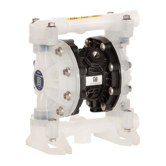
Air-Operated
Diaphragm Pumps
For fluid transfer applications. For professional use only.
100 psi; 0.7 MPa; 7 bar Maximum Fluid Working Pressure
100 psi; 0.7 MPa; 7 bar Maximum Air Input Pressure
ALUMINUM AND STAINLESS STEEL*
These pumps are
M 60
*
*
Important Safety Instructions
Read all warnings and instructions in this manual.
Save these instructions.
certified.
M 60
9065A
VERDERAIR VA 15
Advertisement

Related Manuals for Graco M 60


Summary of Contents for Graco M 60
- Page 1 100 psi; 0.7 MPa; 7 bar Maximum Fluid Working Pressure 100 psi; 0.7 MPa; 7 bar Maximum Air Input Pressure ALUMINUM AND STAINLESS STEEL* These pumps are certified. M 60 9065A VERDERAIR VA 15 Important Safety Instructions Read all warnings and instructions in this manual.
-
Page 2: Table Of Contents
Table of Contents Symbols Safety Warnings ........Warning Symbol Installation . - Page 3 Warning TOXIC FLUID HAZARD Hazardous fluid or toxic fumes can cause serious injury or death if splashed in the eyes or on the skin, inhaled, or swallowed. D Know the specific hazards of the fluid you are using. D Do not lift a pump under pressure. If dropped, the fluid section may rupture. Always follow the Pressure Relief Procedure on page 10 before lifting the pump.
- Page 4 Installation General Information Caution D The Typical Installations in Fig. 2 are only guides for selecting and installing system components. Contact your Safe Operating Temperatures VERDER distributor for assistance in planning a system Minimum (all pumps): 40_ F (4_ C) to suit your needs.
- Page 5 Installation Air Line Installation of Remote Pilot Airlines Connect the air line to the pump as noted above. Warning Connect 1/4 OD tubing to the push type connectors (16) A bleed-type master air valve (B) is required in your system on the underside of the pump.
- Page 6 Installation Fluid Pressure Relief Valve Air Exhaust Ventilation Caution Read Toxic Fluid Hazard on page 3. Some systems may require installation of a pressure relief valve at the pump outlet to prevent over–pressurization and Read Fire and Explosion rupture of the pump or hose. See Fig. 1. Hazard on page 3.
- Page 7 Installation ABOVE-GROUND TRANSFER INSTALLATION Pump Bleed-type master air valve (required for pump) Electrically conductive air supply line Air line quick disconnect Master air valve (for accessories) Air line filter Pump air regulator Fluid drain valve (required) Fluid regulator (optional) Electrically conductive fluid supply hose Fluid suction line Underground storage tank Wall mounting bracket...
- Page 8 Installation Grounding Ground all of this equipment: D Pump: The metal pump has a grounding strip in front of the center housing. The acetal and conductive polypropy- Warning lene pumps have a grounding screw on the top manifold. Connect the non-clamp end of the ground wire to the grounding strip or grounding screw, and connect the FIRE AND EXPLOSION HAZARD clamp end of the ground wire to a true earth ground.
- Page 9 Installation Changing the Orientation of the Fluid Inlet and Torque to 80 to 90 in-lb (9 to 10 NSm). See Torque Outlet Ports VM60) Sequence, page 30. You can change the orientation of the fluid inlet and outlet ports by repositioning the manifolds. For M60, , see Fig. 5. Remove the four manifold nuts (109) or bolts (105).
-
Page 10: Service
Operation Pressure Relief Procedure Check all fittings to be sure they are tight. Use a compat- ible liquid thread sealant on all male threads. Tighten the fluid inlet and outlet fittings snugly. Do not over–tighten Warning the fittings into the pump. Place the suction tube (if used) in the fluid to be pumped. -
Page 11: Torque Sequence
Maintenance Lubrication Tightening Threaded Connections The air valve is lubricated at the factory to operate without Before each use, check all hoses for wear or damage and additional lubrication. If you want to provide additional lubri- replace as necessary. Check to be sure all threaded connec- cation, remove the hose from the pump air inlet and add two tions are tight and leak-free. -
Page 12: Troubleshooting
Troubleshooting Read Pressure Relief Procedure on page 10, and relieve the pressure before you check or service the equip- ment. Check all possible problems and causes before disassembling the pump. PROBLEM CAUSE SOLUTION Pump will not cycle, or cycles once and Air valve is stuck or dirty. - Page 13 Service Air Valve M60 Pumps) NOTE: Air Valve Repair Kit 819.9740 is available. Parts included in the kit are marked with a dagger ({) in Fig. 6 and in the Parts Drawings and Lists. A tube of general purpose grease 819.0184 is supplied in the kit. Service the air valve as follows. See Fig.
- Page 14 Service Ball or Duckbill Check Valves Inlet and Outlet for Pumps with Duckbill Check Valves NOTE: Fluid Section Repair Kit is available. See page 23 to order the correct kit for your pump. Parts included Pumps with duckbill check valves are shipped with the inlet in the kit are marked with a double dagger (}) in manifold on top and the outlet manifold on the bottom.
- Page 15 Service Diaphragms M60 NOTE: Fluid Section Repair Kit is available. See page 23 to order the correct kit for your pump. Parts included in the kit are marked with a double dagger (}) in Fig. 10 and in the Parts Drawings and Lists. General purpose grease 819.0184 and Adhesive 819.9741 are supplied in the kit.
- Page 16 Service Diaphragms M60 Included in Fluid Section Repair Kit. Install with lips facing out of center housing (11). Torque to 35 to 45 in-lb (4.0 to 5.1 NSm). Apply grease. The words “AIR SIDE” on diaphragm and backup diaphragm must face toward diaphragm shaft (15).
-
Page 17: Verderair Va
M60 Pump Listing Your Model No. is marked on the pump’s serial plate. See the listing of existing VERDERAIR VA 20 pumps below: M60 Standard Air Valve M60 for Solenoid Operation Seats Seats Fluid Fluid Ref. No. Section Guides Checks Diaphragms Ref. - Page 18 M 60 Repair Kits NOTE: Order Repair Kits separately. To order the Air Valve Repair Kit, order Part No. 819.9740. Seats Ref. No. Guides Checks Diaphragms 819.5183 819.5176 819.5172 –– 819.5169 819.5162 819.5149 819.5148 –– 819.5135 819.5130 –– 819.5128 819.5124 ––...
- Page 19 M 60 Parts Drawing Included in Air Valve Repair Kit 819.9740 Included in Fluid Section Repair Kits 819.4997 to 819.5189 These parts are unique to the remote operated air motor. Grounding Detail 9070A 28 819.6900...
- Page 20 M 60 Fluid Section Parts List See page 24 for Air Motor Parts List M 60 Fluid Section Parts List Aluminum Pumps Stainless Steel (sst) Pumps Ref. Part No. Description Part No. Description 819.4457 COVER, fluid; aluminum 819.4467 COVER, fluid; sst 819.6964...
- Page 21 Torque Sequence Always follow torque sequence when instructed to torque fasteners. M 15 M 60 Left/Right Fluid Covers Left/Right Fluid Covers Torque bolts to 80–90 in–lb (9–10 NSm) Torque bolts to 80–90 in–lb (9–10 NSm) 1 1 1 1 FRONT VIEW...
-
Page 22: Technical Data
M 60 Technical Data Maximum fluid working pressure ............ -
Page 23: Dimensions
M 60 Dimensions FRONT VIEW 108.0 mm 112.8 mm 3/4 bspt(f) * Pumps with duckbill Fluid Outlet * check valves are shipped with the inlet manifold on 1/4 npt(f) Air Inlet top and the outlet manifold on the bottom. To make... -
Page 24: Performance Charts
Performance Charts Fluid Outlet Pressure Test Conditions: Pump tested in water with inlet submerged. (0.7, 7) Fluid Pressure Curves A at 100 psi (0.7 MPa, 7 bar) air pressure B at 70 psi (0.48 MPa, 4.8 bar) air pressure (0.55, 5.5) C at 40 psi (0.28 MPa, 2.8 bar) air pressure (0.41, 4.1) (0.28, 2.8) - Page 25 Performance Charts Air Consumption Test Conditions: Pump tested in water with inlet submerged. È È È È È (0.84) Air Consumption Curves È È È È È A at 100 psi (0.7 MPa, 7 bar) air pressure È È È È È È È...
-
Page 26: Customer Services/Guarantee
Customer Services/Guarantee CUSTOMER SERVICES If you require spare parts, please contact your local distributor, providing the following details: D Pump Model D Type D Serial Number, and D Date of First Order. GUARANTEE All VERDER pumps are warranted to the original user against defects in workmanship or materials under normal use (rental use excluded) for two years after purchase date. - Page 27 ES PROHLÁŠENÍ O SHODĚ, EÜ VASTAVUSDEKLARATSIOON, EC MEGFElELŐSÉGI NYILATKOZAT, EK ATBILSTĪBAS DEKLARĀCIJA, ES ATITIKTIES DEKLARACIJA, DEKLARACJA ZGODNOŚCI UE, DIKJARAZZJONI-KE TA’ KONFORMITA`, IZJAVA ES O SKLADNOSTI, ES - VYHLÁSENIE O ZHODE, ЕО-ДЕКЛАРАЦИЯ ЗА СЪВМЕСТИМОСТ, DEIMHNIÚ COMHRÉIREACHTA CE, CE-DECLARAŢIE DE CONFORMITATE M 60 Model Modèle, Modell, Modello, Μοντέλο, Modelo, Malli, Mudel, Modelis, Mudell, Модел, Samhail...
Need help?
Do you have a question about the M 60 and is the answer not in the manual?
Questions and answers