Table of Contents
Advertisement
Quick Links
INSTRUCTIONS-PARTS LIST
This manual contains important
warnings and information.
READ AND KEEP FOR REFERENCE.
INSTRUCTIONS
DIVORCED DESIGN
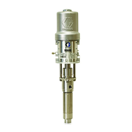
5:1 Ratio Monark Sanitary Pump
600 psi (41 bar) Maximum Fluid Working Pressure
120 psi (8 bar) Maximum Air Input Pressure
Model 207-550, Series E
55 gallon (200 liter) drum size
Table of Contents
. . . . . . . . . . . . . . . . . . . . . . . . . . . . . . . . . . . . . .
. . . . . . . . . . . . . . . . . . . . . . . . . . . . . . .
. . . . . . . . . . . . . . . . . . . . . . . . . . . . . . . . . . . .
. . . . . . . . . . . . . . . . . . . . . . . . . . . . . . . . . . . . .
. . . . . . . . . . . . . . . . . . . . . . . . . . . . . . . . . . .
. . . . . . . . . . . . . . . . . . . . . . . . . . . . . . . .
. . . . . . . . . . . . . . . . . . . . . . . . . . . . . . . . . . . . . .
. . . . . . . . . . . . . . . . . . . . . . . . . . . . . . . . . . . . . . . .
. . . . . . . . . . . . . . . . . . . . . . . . . . . . . . . . . . .
. . . . . . . . . . . . . . . . . . . . . . . . . . . . . . . .
Warranty
. . . . . . . . . . . . . . . . . . . . . . . . . . . . . . . . . . . . .
Graco Toll-Free Phone Number
GRACO INC. P.O. BOX 1441 MINNEAPOLIS, MN 55440-1441
2
2
4
6
7
9
10
12
14
15
16
. . . . . . . . . . . . . . . . .
16
COPYRIGHT 1996, GRACO INC.
Graco Inc. is registered to I.S. EN ISO 9001
307-056
Rev. K
Supersedes F
and PCN G
Advertisement
Table of Contents

Subscribe to Our Youtube Channel
Related Manuals for Graco Monark E Series


Summary of Contents for Graco Monark E Series
-
Page 1: Table Of Contents
Graco Toll-Free Phone Number ....GRACO INC. P.O. BOX 1441 MINNEAPOLIS, MN 55440–1441 COPYRIGHT 1996, GRACO INC. Graco Inc. is registered to I.S. EN ISO 9001... -
Page 2: Symbols
This equipment is for professional use only. Read all instruction manuals, tags, and labels before operating the equipment. Use the equipment only for its intended purpose. If you are not sure, call your Graco distributor. Do not alter or modify this equipment. - Page 3 WARNING FIRE AND EXPLOSION HAZARD Improper grounding, poor ventilation, open flames or sparks can cause a hazardous condition and result in a fire or explosion and serious injury. Ground the equipment. Refer to Grounding on page 4. If there is any static sparking or you feel an electric shock while using this equipment, stop dis- pensing immediately.
-
Page 4: Installation
1. Pump: use a ground wire and clamp. See Fig. 1. NOTE: Always use Genuine Graco Parts and Acces- Loosen the grounding lug locknut (W) and washer sories, available from your Graco distributor. Refer to (X). - Page 5 Installation Air Exhaust Muffler (may alternately be 3/8 npt Air Inlet M Bung-Mounted Sanitary Pump mounted remotely, using exhaust hose) G Air Line Drain Pipe and Valve Dispensing Valve Air Exhaust Hose 3/4 npt Exhaust Air Outlet 1–1/2” Tube Size Flanged Fluid Outlet Sensing Device Pump Ground Wire (required;...
-
Page 6: Operation
Operation Pressure Relief Procedure Allow the pump to cycle slowly until all air is pushed out of the lines (the fluid will be flowing in a steady stream from the fluid outlet) and the pump is primed. WARNING With the air supply turned on, the pump will start when PRESSURIZED EQUIPMENT HAZARD the dispensing valve is opened, and stall against The system pressure must be manually relieved to... -
Page 7: Maintenance
Maintenance IMPORTANT NOTE: 4. Wash all the pump parts with an alkaline detergent at the manufacturer’s recommended temperature The following instructions show a basic procedure for and concentration, using either a brush or other cleaning a sanitary system. However, be sure to clean C.O.P. - Page 8 Notes...
-
Page 9: Troubleshooting
Troubleshooting 1. Relieve the pressure. WARNING 2. Check all possible remedies in the Troubleshooting To reduce the risk of serious injury whenever you Chart before disassembling the pump. are instructed to relieve pressure, always follow the Pressure Relief Procedure on page 6. Problem Cause Solution... -
Page 10: Service
Service Displacement Pump Disassembly Displacement Pump Assembly NOTE: Lubricate the o-rings, throat packings, and NOTE: Repair Kit 218–741 is available. The parts piston seals with waterproof approved sanitary lubri- included in the kit are marked with an asterisk (for cant when reassembling. example, 8*). - Page 11 Service See Detail A. Detail A: Throat Packing Assembly See Detail B. See Detail C. Lips must face up. Lips must face down. Lubricate with sanitary lubricant. 0628 Detail B: Piston Valve Assembly 0629 Detail C: Intake Valve Assembly 3 (Ref) 0630 Fig.
-
Page 12: Parts
Parts... - Page 13 Parts Part No. Description Part No. Description 207–546 AIR MOTOR 169–845 PIN, retaining, piston housing See 307–043 for parts 169–846 HOUSING, piston 207–551 CYLINDER, pump 174–036 LABEL, designation (not shown) 156–082 O-RING; buna-N 207–552 ROD, displacement 101–946 PIN, cotter; 0.12” (3.2 mm) x * These parts are included in Repair Kit 218–741, 1”...
-
Page 14: Dimensions
Dimensions 11 in. (280 mm) 3/8 npt(f) Air Inlet Grounding 7.88 in. (201 mm) 3/4 npt(f) Air Exhaust Outlet 5.69 in. (145 mm) dia. 1–1/2 in. Size Tube Flange Fluid Outlet 56.8 in. (1443 mm) 45 in. (1143 mm) 36.7 in. (933 mm) 2.12 in. -
Page 15: Technical Data
Technical Data Category Data Maximum fluid working pressure 600 psi (41 bar) Maximum air input pressure 120 psi (8 bar) Ratio Pump cycles per gallon (3.8 liters) Fluid flow at 60 cycles per minute 2.3 gallons (8.7 liters) Air consumption approximately 8 scfm (0.224 m /minute) per gallon (3.8 liters) at 100 psi (7 bar) air pressure Minimum air hose size...
Need help?
Do you have a question about the Monark E Series and is the answer not in the manual?
Questions and answers