Table of Contents
Advertisement
Quick Links
Instructions – Parts List
Parts
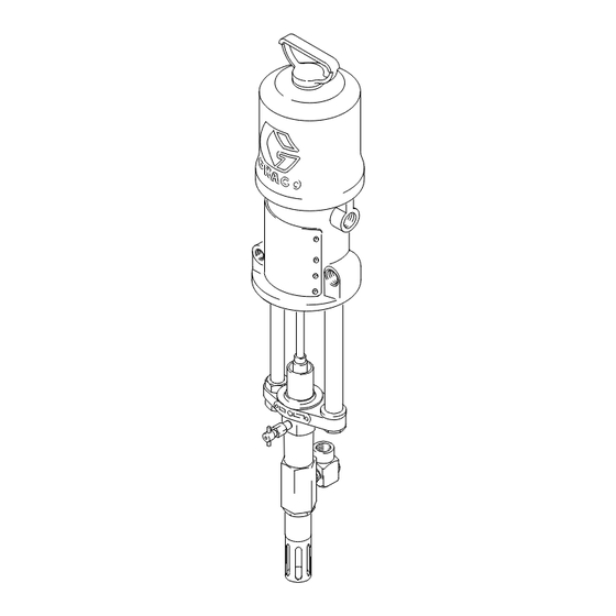
Presidentr Pump
WITH PRIMING PISTON
24:1 Ratio Models
4320 psi (29.8 MPa, 298 bar) Maximum Fluid Working Pressure
Part No. 205791, Series E
5 & 10 gallon (19 & 38 liter) Pail Size
Part No. 205792, Series E
55 gallon (200 liter) Drum Size
Part No. 206738, Series E
5 gallon (19 liter) Ram Size
48:1 Ratio Models
4800 psi (33.1 MPa, 331 bar) Maximum Fluid Working Pressure
Part No. 206597, Series F
5 & 10 gallon (19 & 38 liter) Pail Size
Part No. 206739, Series E
5 gallon (19 liter) Ram Size
Read warnings and instructions.
See page 2 Table of Contents.
WARNING
Never exceed 100 psi (0.7 MPa, 7 bar) maximum
air pressure to the 48:1 President pump. Do not
exceed the maximum working pressure of any
component or accessory used in the system.
GRACO INC. P.O. BOX 1441 MINNEAPOLIS, MN 55440-1441
Copyright 2001, Graco Inc. is registered to I.S. EN ISO 9001
306746K
TI1807A
Advertisement
Table of Contents

Related Manuals for Graco President E Series


Summary of Contents for Graco President E Series
- Page 1 48:1 President pump. Do not exceed the maximum working pressure of any component or accessory used in the system. TI1807A GRACO INC. P.O. BOX 1441 MINNEAPOLIS, MN 55440-1441 Copyright 2001, Graco Inc. is registered to I.S. EN ISO 9001...
- Page 2 D Read all instruction manuals, tags, and labels before operating the equipment. D Use the equipment only for its intended purpose. If you are not sure, call your Graco distributor. D Do not alter or modify this equipment. Use only genuine Graco parts and accessories.
- Page 3 WARNING FIRE AND EXPLOSION HAZARD Improper grounding, poor ventilation, open flames or sparks can cause a hazardous condition and result in a fire or explosion and serious injury. D Ground the equipment and the object being sprayed. Refer to Grounding on page 5. D If there is any static sparking or you feel an electric shock while using this equipment, stop spray- ing immediately.
- Page 4 WARNING TOXIC FLUID HAZARD Hazardous fluid or toxic fumes can cause serious injury or death if splashed in the eyes or on the skin, inhaled, or swallowed. D Know the specific hazards of the fluid you are using. D Store hazardous fluid in an approved container. Dispose of hazardous fluid according to all local, state and national guidelines.
-
Page 5: General Information
NOTE: Reference numbers and letters in parentheses in the text refer to the callouts in the figures and the parts drawing. NOTE: Always use Genuine Graco Parts and Acces- sories, available from your Graco distributor. If you supply your own accessories, be sure they are ade- quately sized and pressure rated for your system. -
Page 6: Mounting The Pump
Installation Mounting the Pump WARNING Two accessories, the bleed–type master air valve Mount the pump to suit the type of installation planned. (G), and the fluid drain valve (R), are required for The pump dimensions and mounting hole layout are your system to reduce the risk of serious bodily shown on page 16. - Page 7 Installation Air Supply Line Air Line Filter M Whip Hose Air Regulator Air Line Oiler Fluid Shutoff Valve G Bleed–Type Master Air Valve Fluid Hose O Air Shutoff Valve Drain Valve 1/2 npt(f) 1 in. npt TI1808A Fig. 2 306746...
-
Page 8: Pressure Relief Procedure
Operation Pressure Relief Procedure 5. Leave the drain valve open until you are ready to spray again. WARNING If you suspect that the spray nozzle or hose is com- pletely clogged, or that pressure has not been fully FLUID INJECTION HAZARD relieved after following the steps above, very slowly The system pressure must be manually relieved to loosen the nozzle retaining ring or hose end coupling... -
Page 9: Starting And Adjusting The Pump
Operation Starting and Adjusting the Pump Fill the wet–cup (25) half full with Graco Throat Seal Liquid (TSL). With the drain valve and bleeder valve closed, and the gun/valve safety disengaged, trigger the gun/valve and slowly open the air supply valve until the pump starts. -
Page 10: Maintenance
Keep the wet–cup (25) filled with Graco Throat Seal solvent. Eliminate all air from fluid system. Liquid (TSL). See Fig. 3. Check tightness of packing For overnight shutdown, follow the Pressure Relief nut (36 or 60) weekly. -
Page 11: Troubleshooting
Troubleshooting D Whenever you replace the packings, also replace WARNING the glands and bearing. To reduce the risk of serious injury whenever you D When cleaning parts, use a compatible solvent. are instructed to relieve pressure, always follow the Pressure Relief Procedure on page 8. Inspect parts for wear or damage and replace as necessary. -
Page 12: Displacement Pump Service
Displacement Pump Service 3. Unscrew the booster cylinder (34 or 61) from the WARNING pump housing (11) and pull the booster rod (35), intake valve assembly, and displacement rod from To reduce the risk of serious injury whenever you the bottom of housing. are instructed to relieve pressure, always follow the Pressure Relief Procedure on page 8. - Page 13 Service 49, 66 58, 26 36, 60 34, 61 33, 59 31, 63 TI1812A Fig. 5 8. Turn the air motor upside down and place the fluid pump on the mounting tubes (P, Q). Leaving the coupling nut (22) loose, move the pump to align with the rods.
- Page 14 Parts Model 205791, Series E Model 206739, Series F 24:1 Ratio President Pump, 5 and 10 gal size 48:1 Ratio President Pump, 5 gal size Includes items 1–49 Includes items 1, 40–46, 57, and 64–66 Model 205792, Series E Model 206597, Series F 24:1 Ratio President Pump, 55 gal size 48:1 Ratio President Pump, 5 and 10 gal size Includes items 1–36, 40–46, and 51–56...
- Page 15 Parts 49, 66 36, 60 32** 62** 31**, 63** 62** 48, 55, 65 33, 59 28** 29** 37, 51, 64 26, 58 34, 61 TI1814A 306746...
- Page 16 Dimensions Model No. Overall Pump Fluid Length Length Pump 36–5/8 in. 20–3/8 in. 14–3/8 in. 205791 (930 mm) (518 mm) (364 mm) 48–3/4 in. 32–1/2 in. 15–1/8 in. 205792 (1238 mm) (826 mm) (384 mm) 36–5/8 in. 20–3/8 in. 14–3/8 in. 206597 16–3/8 in.
-
Page 17: Technical Data
Technical Data Category Data Maximum working pressure 24:1 pump: 4320 psi (29.8 MPa, 298 bar) 48:1 pump: 4800 psi (33.1 MPa, 331 bar Recommended air operating range 24:1 pump: 40–180 psi (0.28–1.24 MPa, 2.8–12.4 bar) 48:1 pump: 40–100 psi (0.28–0.7 MPa, 2.8–7 bar) Air consumption 24:1 pump: approx. -
Page 18: Graco Standard Warranty
Graco distributor to the original purchaser for use. With the exception of any special, extended, or limited warranty published by Graco, Graco will, for a period of twelve months from the date of sale, repair or replace any part of the equipment determined by Graco to be defective.
Need help?
Do you have a question about the President E Series and is the answer not in the manual?
Questions and answers