Kamstrup MULTICAL 801 Installation And User Manual
Hide thumbs
Also See for MULTICAL 801:
- Technical description (121 pages) ,
- Installation manual (12 pages)

Subscribe to Our Youtube Channel
Related Manuals for Kamstrup MULTICAL 801


Summary of Contents for Kamstrup MULTICAL 801
- Page 1 Installation and User Guide MULTICAL® 801 Kamstrup A/S · Industrivej 28, Stilling · DK-8660 Skanderborg · T: +45 89 93 10 00 · info@kamstrup.com · kamstrup.com...
- Page 2 When the upper front key is activated, a new reading appears. The lower front key is used to show historical readings and average values. 4 minutes after the front key has been activated reading of consumed energy will automatically appear. Kamstrup A/S • 5512603_C1_GB_03.2016...
- Page 3 Installation Guide MULTICAL® 801 Kamstrup A/S · Industrivej 28, Stilling · DK-8660 Skanderborg · T: +45 89 93 10 00 · info@kamstrup.com · kamstrup.com...
- Page 4 24 V active pulse output. Irrespective of flow sensor type, ”pulses/litres” must be identical in flow sensor and calculator. Battery for replacement Kamstrup type 66-99-619. Kamstrup A/S • 5512603_C1_GB_03.2016...
-
Page 5: Table Of Contents
Examples of connections 8.15 Module overview Data modules 8.16 Insertion of modules 8.1 GSM/GPRS module (GSM6H), Information codes ”INFO” 24 type 67-0Z 8.2 3G GSM/GPRS module Terminal Overview (GSM8H), type 67-0U 8.3 Ethernet/IP module (IP201), type 67-0T Kamstrup A/S • 5512603_C1_GB_03.2016... -
Page 6: General Information
MULTICAL® 801 General information Please read this guide before installing the energy meter. If the meter is installed incorrectly, Kamstrup’s warranty obligations will no longer apply. Please note that the following installation conditions must be obeyed: - Pressure stage ULTRAFLOW®: PN16/PN25/PN40, see marking. Marking of flow part does not cover included accessories. -
Page 7: Mounting Of Temperature Sensors
M 10 socket for the short direct sensor. They can also be mounted in installations with standard angle tee-pipes. Kamstrup supply R½ and R¾ brass nipples, which fit our short, direct sensor. Make sure that the tip of the temperature sensor reaches at least the center of the flow pipe. -
Page 8: Mounting Of Flow Sensor
Correct flow sensor position (inlet or outlet pipe) appears from the front label of the MULTICAL® 801. The flow direction is indicated by an arrow on the flow sensor. Kamstrup A/S • 5512603_C1_GB_03.2016... -
Page 9: Mounting Of Couplings And Short Direct Sensor Mounted In Ultraflow® Flow Part
Mounting of couplings and short direct sensor mounted in ULTRAFLOW® flow part The short direct sensor from Kamstrup can only be mounted in PN16 installations. The blind plug mounted in the ULTRAFLOW® can be used in connection with both PN16 and PN25. - Page 10 ULTRAFLOW® must be min. 1.5 bar at q and min. 2.5 bar at . This applies to temperatures up to approx. 80 °C. ULTRAFLOW® must not be exposed to lower pressure than the ambient pressure (vacuum). Kamstrup A/S • 5512603_C1_GB_03.2016...
-
Page 11: Mounting Of Ultraflow® ≤ Dn125
If condensation is likely, e.g. in 45° cooling systems, an ULTRAFLOW® which is protected against condensation must be used. Mounting of ULTRAFLOW® 54 ≥ DN150 See installation instructions No. 5512-887. Kamstrup A/S • 5512603_C1_GB_03.2016... -
Page 12: Mounting Of Calculator
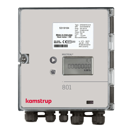
Con: 21200040300 Class: E2, M1 Imp/l: Meter in flow pipe 1,5 m³/h Heat meter / 4W Non-condensing/Closed DK-0200 θ : 2°C…180°C MI004-009 ∆Θ :3K…170K Pt 500-EN 60751 IP67 (5-55°C) MULTICAL® MULTICAL® 801 installation dimensions 80,5 104,5 Kamstrup A/S • 5512603_C1_GB_03.2016... -
Page 13: Power Supply
Open thermo-regulators and cocks in order to establish a water flow through the heating system. Activate the upper push button on the MULTICAL® 801 and check that the display values for temperature and water flow are reliable. Kamstrup A/S • 5512603_C1_GB_03.2016... -
Page 14: Electrical Connection
V2 11–9–69 Flow sensor in Flow sensor in outlet flow pipe outlet pipe T3 51–51A– Tank/heat Reference sensor 52A–52 exchanger (grey) temperature Other makes of flow sensors are usually connected to terminals 10B and 11B. Kamstrup A/S • 5512603_C1_GB_03.2016... -
Page 15: Examples Of Connections
100 m between flow sensor and calculator. Heat energy Cooling energy Same DΘ polarity E2 = V2 (T1-T2)k E1 = V1 (T1-T2)k Changed DΘ polarity E2 = V2 (T1-T2)k E3 = V1 (T2-T1)k Kamstrup A/S • 5512603_C1_GB_03.2016... - Page 16 98A is added to the passive contact output on terminals 24 and 25 before the signal is connected to the galvanically separated flow sensor input. This permits a cable length of up to 100 m between flow sensor and calculator. Kamstrup A/S • 5512603_C1_GB_03.2016...
-
Page 17: Data Modules
The module has no built-in security and must, therefore, always be used in connection with a firewall or NAT. Further details appear from the data sheet (DK: 5810541, GB: 5810542, DE: 5810543, SE: 5810544) . Kamstrup A/S • 5512603_C1_GB_03.2016... -
Page 18: M-Bus, Type
For further information on radio please refer to Technical Description for Radio (5512-013) . The pulse inputs in this module are identical with the ones described earlier. 680K 11K2 0.1 µ 11K2 680K 11K2 0.1 µ 11K2 Kamstrup A/S • 5512603_C1_GB_03.2016... -
Page 19: Prog. Data Logger + Rtc + 4
Wireless M-Bus, type 67-00-30/67-00-31/67-00-35/67-00-38 The radio module has been designed to form part of the hand-held Wireless M-Bus Reader systems of Kamstrup A/S at license-free radio frequency (868 MHz). The module fulfils the C-mode specifications of prEN13757-4 and can thus form part of other systems using Wireless M-Bus C-mode communication. -
Page 20: Siox Module
BACnet® Controller. The two pulse inputs allow connection and reading of two additional meters for e.g. water and electricity with pulse output. Kamstrup A/S • 5512603_C1_GB_03.2016... - Page 21 8.14 High Power Radio Router + 2 pulse inputs (VA, VB), type 67-00-84 The High Power RadioRouter module has built-in router functionality and is thus optimized to form part of a Kamstrup radio network, the read data being automatically transferred to system software via the network unit RF Concentrator.
-
Page 22: 8.15 Module Overview
Metasys N2 (RS-485) + pulse inputs 5550-1110 67-00-64 SIOX module (Auto detect baud rate) 5920-193 67-00-66 BACnet MS/TP (B-ASC) RS-485 + pulse inputs 5550-1240 67-00-67 Modbus RTU + pulse inputs 5550-1277 67-00-84 High Power RadioRouter + pulse inputs 5550-1221 Kamstrup A/S • 5512603_C1_GB_03.2016... -
Page 23: 8.16 Insertion Of Modules
8.16 Insertion of modules Data modules are retrofitted by placing the module in the PCB holder in the left side of the meter and ”clicking” on the module. Module and meter are electrically connected using a 6-pole jumper. Kamstrup A/S • 5512603_C1_GB_03.2016... -
Page 24: Information Codes "Info
Flow sensor V2, Signal too low (Air) After reset and 1 day (00:00) 16384 Flow sensor V1, Wrong flow direction After reset and 1 day (00:00) 32768 Flow sensor V2, Wrong flow direction After reset and 1 day (00:00) Kamstrup A/S • 5512603_C1_GB_03.2016... -
Page 25: 10 Terminal Overview
69 10B 11B 11 + A1 - + A2 - + A3 - + A4 - + V2 - + V1 - 0/4-20 mA Outputs Load: 0-500 ohm Serial DATA Flow Flow KMP Protocol Meter ULTRAFLOW® Meter ULTRAFLOW® Kamstrup A/S • 5512603_C1_GB_03.2016... - Page 26 MULTICAL® 801 Kamstrup A/S • 5512603_C1_GB_03.2016...
- Page 27 User Guide Consumed energy in kWh, MWh Latest yearly target date. or GJ. Energy consumption count on latest yearly target date, followed by previous yearly target date. Followed by monthly target date data. Consumed district heating water. Date of latest yearly target date. District heating water volume count on latest yearly target date, followed by previous yearly...
- Page 28 In this example: Installed in outlet flow, MWh and 100 imp/l. Followed by the calculator’s configuration number and software edition. Display segment test. DDD = 213 (*) DDD = 212 Also see interactive user guides at products.kamstrup.com. Kamstrup A/S • 5512603_C1_GB_03.2016...
Need help?
Do you have a question about the MULTICAL 801 and is the answer not in the manual?
Questions and answers