Telguard TG-4 Installation And Operation Instructions Manual
Residential & small business cellular alarm communicator
Hide thumbs
Also See for TG-4:
- Quick install manual (8 pages) ,
- Installation and operating instructions manual (28 pages) ,
- Quick installation manual (2 pages)
Table of Contents
Advertisement
TELGUARD
R
ESIDENTIAL
C
ELLULAR
I
NSTALLATION AND
PROPRIETARY INFORMATION For use by TELGUARD
Note: The registration form must be completed before leaving for the installation site. The
registration form may be completed online through our 24/7 dealer portal www.telguard.com.
F
OREWORD
Dealers purchase Telguard
represent. The Telguard model TG-4 (p/n TG4LA002) is UL Listed for Household Fire systems,
Household Burglary systems and Miscellaneous Supplemental Use. This means that the TG-4 may
56050301 – Rev B
TG-4
& S
A
LARM
I
NSTRUCTIONS
Revised August 17, 2017
Distribution to others strictly prohibited.
®
cellular communicators for the quality, features and total value they
i
®
DIGITAL
B
MALL
USINESS
C
OMMUNICATOR
O
PERATING
®
customers only.
© 2017 Telguard
Advertisement
Table of Contents
Troubleshooting

Related Manuals for Telguard TG-4


Summary of Contents for Telguard TG-4
- Page 1 Dealers purchase Telguard cellular communicators for the quality, features and total value they represent. The Telguard model TG-4 (p/n TG4LA002) is UL Listed for Household Fire systems, Household Burglary systems and Miscellaneous Supplemental Use. This means that the TG-4 may 56050301 –...
-
Page 2: About This Manual
It is our goal at Telguard to always supply accurate and reliable documentation. If a discrepancy is found in this documentation, please mail or fax a photocopy of the corrected material to:... -
Page 3: Fcc Notices
Standard. The design of your Telguard complies with this updated Standard. Of course, if you want to limit RF exposure even further than the updated ANSI Standard, you may choose to install the unit in a manner that locates its antenna at an even greater distance from the general public than is recommended as a minimum by the standard. -
Page 4: Repair And Warranty
Do not transport or store flammable gas, liquid or explosives in the area where your Telguard Digital or its accessories are located. - Page 5 Telguard will repair or replace (our option) inoperative units for up to two years from date of manufacture. This excludes damage due to lightning or installer error. Unauthorized modifications void this warranty. Telguard is not responsible for incidental or consequential damages. Liability is limited to the price of the unit.
-
Page 6: Terms And Conditions For Use Of Telguard Product
ELGUARD RODUCT These Terms and Conditions are a legal contract between you and Telguard for the title to and use of the Product. BY RETAINING AND USING THE PRODUCT YOU AGREE TO THE TERMS AND CONDITIONS INCLUDING WARRANTY DISCLAIMERS, LIMITATIONS OF LIABILITY AND INDEMNIFICATION PROVISIONS BELOW. -
Page 7: Table Of Contents
Technical Support......................ii About this Manual ......................ii FCC Notices........................iii Repair and Warranty ......................iv Terms and Conditions for Use of Telguard Product ............. vi Table of Contents......................vii General Description and Operation ................. 1 Features ..........................1 Operating Mode .......................... 1 Multiple Alarm Format Support.................... - Page 8 Step 4: Activate & Transmit Alarms over Cellular Network ..........11 Step 5: Connect Supervisory Trip Outputs ................14 Step 6: Connect and Test the Trip Input (optional)............... 15 Step 7: Complete the Telguard Installation ................15 Appendix 1 – Connection Guide..................16 Wiring Diagram......................... 16 Jack Assignments........................
-
Page 9: General Description And Operation
When transmitting an alarm signal using the cellular path, the Telguard obtains its data from the alarm panel by way of a Telco line interface. The Telguard will obtain all alarm signal information including monitoring station phone number, account number and all zones for every alarm transmission. -
Page 10: Complete Supervision Of Communication Path
TCC. It is the responsibility of the installer to verify Standard Line Security from the Listed control unit to the Listed receiver through the TG-4 as marked on the alarm panel and as indicated in the control unit manufacturer's installation instructions. -
Page 11: Complete Power Supervision
Telguard seizes the line and takes over as the main communication path for the alarm panel. If the Telguard goes into CFC, then it will not allow the panel to communicate via Telco again until the panel has been on-hook for 10 consecutive minutes. -
Page 12: Telguard Automatic Self-Test Report
Total loss of power to the Telguard does not prevent transmission of alarm messages from the alarm panel “through” the Telguard and out over an operative phone line. If power is connected properly to the unit when a CF occurs, please contact Telguard Technical Support for resolution. -
Page 13: Programmable Supervisory Trip Output (Stc) Relays
Telguard to upload current operational status data and historical data, just as the automatic self-test described above, except that the query signal is controlled by the one who initiates it. The query signal is held in the Telguard database at the TCC for review and is not forwarded on to the central station. -
Page 14: Complete Factory Reset Option
ESET PTION A special function within the TG-4 allows you to perform a complete Factory Reset on the unit. This reset will change all unit settings back to a factory default configuration. Note: Never attempt to do a Complete Factory Reset on an active account. -
Page 15: Getting Ready
EALER CCOUNT STABLISHMENT A Dealer Account must be established prior to registration of any Telguard unit. This can be accomplished by visiting www.telguard.com and completing the necessary information under “Dealer Signup”. -
Page 16: Installation
This seven-step installation approach provides the alarm installer with the easiest and fastest method of properly installing your Telguard TG-4. Please follow the instructions carefully and if you should need assistance or have any questions, call Telguard TECHNICAL SUPPORT at 1-800-229-2326 extension 9. -
Page 17: Step 2: Locate Unit And Measure Signal Strength (Rssi)
Telguard is configured with the butt-set to send trip input events to the TCC, a default notification will be sent to the central station. If the Telguard is configured to report restorals, the contact closure will also be reported. - Page 18 If moving the TG-4 to a different location is not practical, then you may need a cable and remote the antenna in order to receive adequate radio signal strength. Pick a high, visually secure spot using the guidelines below.
-
Page 19: Step 3: Verify Panel Alarms Over The Telco Connection
Connect alarm panel and Telco line to the Telguard. Plug the modular jack of the alarm panel into the black jack of the Telguard and the incoming Telco connection into gray jack. Trip a zone on the alarm panel and transmit over the Telco line. This step is important to verify the panel is programmed with valid account code and central station information before transmitting signals through the cellular network. - Page 20 If LED 1 and LED 4 are flashing, the Telguard has failed activation. The serial number is not in the database at the TCC. Clear the fault (see note below) and call Telguard Technical Support to verify proper registration before resending an alarm signal.
- Page 21 RANSMISSIONS OVER ELLULAR Before beginning this step, disconnect the Telco line from the TG-4’s gray jack that goes to the incoming Telco connection at the premise. Trip several alarms on the alarm panel and verify that the central station received them by calling the central station operator.
-
Page 22: Step 5: Connect Supervisory Trip Outputs
At this point reconnect the Telco line to the TG-4’s gray jack that goes to the incoming Telco connection at the premise. 5: C ONNECT UPERVISORY UTPUTS Connect and test the supervisory trip outputs to the alarm panel. Enabling of a local alarm or strobe light may be desirable when a trip is declared. The STC trip output can be used directly to activate a local signaling device, provided that the trip output is not needed to trip the host control/communicator at the same time. -
Page 23: Step 6: Connect And Test The Trip Input (Optional)
(i.e. a cut wire) can be detected. When the trip input functionality is being used, closing the trip contact will cause the Telguard TG-4 to send a message to the TCC, which in turn will cause the TCC to send a message to the central station. -
Page 24: Appendix 1 - Connection Guide
Battery Connector IDLE TELGUARD WAIT ING FOR RESPO NSE FROM TCC TMC COMM Battery wire Digital TG-4 should be at FLASHIN G ACTIVATION DENIED least ¼ inch apart from AC IDLE , PR OVISIONED BY CDM A N ETWORK PANEL... -
Page 25: Jack Assignments
8 = Gray T1 Digital Dialer Connects alarm If PPF is ENABLED BLACK 1 = Brown R1 input/output of panel to TG-4 for STC LED 2 will flash (J13) 2 = Blue host alarm transmitting alarms 7 times when alarm 4 = Green R (Ring) panel. -
Page 26: Ac Terminal Strip Pin Assignments
The installer should verify the complete compatibility at the time installation. 2 – T PPENDIX ROUBLESHOOTING UIDE This section provides a summary of all LED indications and their meanings, as well as the expected behavior of the TG-4 under various exception conditions. 56050301 – Rev B © 2017 Telguard... - Page 27 Condition) 5 Flashes* STC – RFC 6 Flashes* STC – DTF 7 Flashes* STC – PPF Alarm panel idle (TG-4 is primary) LED 3 MODE Yellow Flash*(1 sec) Alarm panel off-hook to transmit signals over cellular. Solid On Alarm panel idle (TG-4 is backup)
- Page 28 -70 3½ LED 5-3 = on, LED 2 = slow flash -60 LED 5-2 = on Note: When LED 1 is on this indicates more than one cellular tower within range. 56050301 – Rev B © 2017 Telguard...
-
Page 29: Troubleshooting Quick Reference Table
Note: If several trouble conditions are present, the STC LED will flash all of the indications in sequence. 3 – D PPENDIX ETAILED PECIFICATIONS IALER TO NTERFACE LECTRONICS The patented integrated interface by Telguard, allows digital dialers to dial into the cellular radio network. 56050301 – Rev B © 2017 Telguard... -
Page 30: Power
16VDC 28mA (idle), 117mA (transmitting) IGITAL ELLULAR ADIO The Telguard TG-4 radio provides data connectivity on LTE networks. The TG-4 transceiver is FCC compliant, meeting all requirements of Part 15 and 27 testing. It is also compliant to the PTCRB requirements. ... -
Page 31: Appendix 4 - Parts List
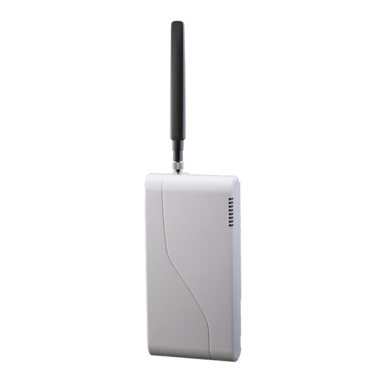
Model TG-4 Model TG-4 (p/n TG4LA002) meets the requirements for Household Burglary, Household Fire, and Combination Burglary/Fire installations. It p/n TG4LA002 has a plastic enclosure, and cellular antenna. TG-4 is UL Listed for the following: UL 1023 – Household Burglary ...
Need help?
Do you have a question about the TG-4 and is the answer not in the manual?
Questions and answers