
Related Manuals for SICK IOLG2PN-03208R01-PROFINET


Summary of Contents for SICK IOLG2PN-03208R01-PROFINET
- Page 1 O P E R AT I N G I N S T R U C T I O N S IOLG2PN-03208R01 – PROFINET IO-Link Master...
- Page 2 Alteration or abridgment of the document is not permitted without the explicit written approval of SICK AG. © SICK AG • Presence Detection • Subject to change without notice • 8018665.10RD...
-
Page 3: Table Of Contents
“PROFINET” connection diagram ......18 5.3.3 “IO-Link port” connection diagram ......18 System integration and configuration..........19 6.1 Configuring module properties ..........26 Bit mapping and function of the modules ......27 © SICK AG • Presence Detection • Subject to change without notice • 8018665.10RD... - Page 4 11.1 Dimensions ................45 11.2 Power supply ................46 11.3 PROFINET ................46 11.4 Ambient conditions ..............46 11.5 Structural design ..............47 Index ......................48 © SICK AG • Presence Detection • Subject to change without notice • 8018665.10RD...
-
Page 5: General Information
… highlights useful tips and recommendations as well as information for efficient and trouble-free operation. Abbreviations Abbreviation Description PROFINET Electromagnetic compatibility Functional grounding Input Output Table 1: Abbreviations © SICK AG • Presence Detection • Subject to change without notice • 8018665.10RD... -
Page 6: Limitation Of Liability
In order to allow us to deal with the matter quickly, please note down the type designation and order number before calling. This information can be found on the side of the IO-Link Master. © SICK AG • Presence Detection • Subject to change without notice • 8018665.10RD... -
Page 7: Eu Declaration Of Conformity
Operating instructions IO-Link Master IOLG2PN-03208R01 – PROFINET General information EU Declaration of Conformity → You can download the EU declaration of conformity via the Internet from “www.sick.com”. © SICK AG • Presence Detection • Subject to change without notice • 8018665.10RD... -
Page 8: Safety
SICK AG assumes no liability for losses or damage arising from the use of the product, either directly or indirectly. This applies in particular to use of the product that does not conform to its intended purpose and is neither described nor mentioned in this documentation. -
Page 9: Requirements For Qualified Personnel
In Germany, electrical specialists must meet the specifications of the work safety regulation BGV A3 (e.g., master electrician). Other relevant regulations applicable in other countries must be observed. © SICK AG • Presence Detection • Subject to change without notice • 8018665.10RD... -
Page 10: Setup And Function
æ Port 5 (IO-Link, Standard I/O) 7 Port 2 (IO-Link, Standard I/O) ç Port 7 (IO-Link, Standard I/O) 8 Port 4 (IO-Link, Standard I/O) 9 Port 6 (IO-Link, Standard I/O) © SICK AG • Presence Detection • Subject to change without notice • 8018665.10RD... -
Page 11: Function
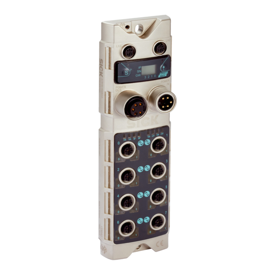
Operating instructions IO-Link Master IOLG2PN-03208R01 – PROFINET Setup and function Function The IOLG2PN-03208R01 IO-Link Master is a remote IO-Link input and out- put module for integration into a PROFINET network. The eight ports can be configured and used independently of one another. They can either be configured as IO-Link ports or standard I/O ports. © SICK AG • Presence Detection • Subject to change without notice • 8018665.10RD... -
Page 12: Status Indicators And Operating Elements
IO-Link port Pin 4 signal status Pin 2 signal status Standard I/O port Pin 2 signal status Pin 4 signal status Table 2: Pin/port LEDs: Assignment © SICK AG • Presence Detection • Subject to change without notice • 8018665.10RD... - Page 13 • Short-circuit on relevant output, either between pin 2 and pin 3 and/or between pin 4 and pin 3 • No high signal on the diagnostic input Table 5: Pin/port LEDs: Standard I/O port © SICK AG • Presence Detection • Subject to change without notice • 8018665.10RD...
- Page 14 • Incorrect configuration of IO-Link data length • Data storage failed • Incorrect IO-Link device for data storage IO-Link short-circuit between pin 3 and pin 4 Table 6: Pin/port LEDs: IO-Link port © SICK AG • Presence Detection • Subject to change without notice • 8018665.10RD...
-
Page 15: Mounting
Equipment damage due to incorrect supply voltage! An incorrect supply voltage may result in damage to the equipment. • Protect the supply voltage with max. 8 A fuses. © SICK AG • Presence Detection • Subject to change without notice • 8018665.10RD... -
Page 16: Io-Link Master Electrical Connection
3. Connect supply voltage to “POWER IN” using a suitable cable. 4. Make fieldbus connection via PROFINET port 1/PROFINET port 2. 5. Connect IO-Link devices or standard devices to the IO-Link ports. 6. If provided, connect the next gateway to “POWER OUT”. © SICK AG • Presence Detection • Subject to change without notice • 8018665.10RD... -
Page 17: Connection Diagrams
Functional grounding DC 24 V IO-Link Master and/or sensor supply DC 24 V Actuator supply Table 7: Description of “POWER IN” and “POWER OUT” supply voltage © SICK AG • Presence Detection • Subject to change without notice • 8018665.10RD... -
Page 18: Profinet" Connection Diagram
IO-Link, input or output Not connected Not connected Table 10: IO-Link port description, M12 female connector, A-coded, 5-pin For the digital sensor inputs, see EN 61131-2, type 2. © SICK AG • Presence Detection • Subject to change without notice • 8018665.10RD... -
Page 19: System Integration And Configuration
Integrating the IO-Link Master You can search for devices using the hardware catalog and move to the PROFINET string using Drag & Drop. Fig. 8: Hardware catalog © SICK AG • Presence Detection • Subject to change without notice • 8018665.10RD... - Page 20 Overview of assignment of slots and modules Device name, PROFINET address The communication parameters of the IO-Link Master are displayed by double-clicking on IO-Link Master in the “Device overview” window. © SICK AG • Presence Detection • Subject to change without notice • 8018665.10RD...
- Page 21 Click the right mouse button on the selected module. Press Assign device names. The tool starts with which you can assign a device name to a module. © SICK AG • Presence Detection • Subject to change without notice • 8018665.10RD...
- Page 22 Assign the device name to the marked and found device using the com- mand “Assign name”. The device name must be identical to the names previously configured under “Properties”. See Page 21. The identification is done via the MAC address or via the flash test. For the MAC address refer to the type label on the back of the IO-Link Master. © SICK AG • Presence Detection • Subject to change without notice • 8018665.10RD...
- Page 23 Configuring port as standard I/O port: For each port you can assign pin 4 and pin 2 the function “normally closed” or “normally open”. The function “Diagnostic input” is additionally available for pin 2. © SICK AG • Presence Detection • Subject to change without notice • 8018665.10RD...
- Page 24 IO-Link module in the catalog and move it to the corre- sponding slot per Drag & Drop. Refer to the documentation for the IO-Link device for the required process data lengths of the IO-Link device. © SICK AG • Presence Detection • Subject to change without notice • 8018665.10RD...
- Page 25 During the selection of the IO-Link module you can change the IO-Link pa- rameter of the respective port/pin using the “Assembly parameters” menu item. For more information, see Page 26, Chapter 6.1 and Page 27, Chap- ter 6.2. © SICK AG • Presence Detection • Subject to change without notice • 8018665.10RD...
-
Page 26: Configuring Module Properties
Normally closed An IO-Link device can be configured via IO-Link and then after configuration set in an SIO module, in which the IO-Link port/pin func- tions as a simple normally closed input. Table 12: Port functionality © SICK AG • Presence Detection • Subject to change without notice • 8018665.10RD... -
Page 27: Bit Mapping And Function Of The Modules
Bit 4 Bit 3 Bit 2 Bit 1 Bit 0 Port 7 Port 6 Port 5 Port 4 Port 3 Port 2 Port 1 Port 0 © SICK AG • Presence Detection • Subject to change without notice • 8018665.10RD... - Page 28 Input the actual process data length of the IO-Link device in the field “Max. input data length”. Using an IO-Link module with corresponding process data length you can adapt the visible data window to the input data. © SICK AG • Presence Detection • Subject to change without notice • 8018665.10RD...
- Page 29 • VID = 26 (SICK AG) • DID = 8388615 (0x800007) • VID: 0 • VID1: 26 • DID0: 128 (0x28) • DID1: 0 (0x00) • DID2: 7 (0x07) © SICK AG • Presence Detection • Subject to change without notice • 8018665.10RD...
- Page 30 In order to use an IO-Link device of a different type, you must delete the content of the parameter server. © SICK AG • Presence Detection • Subject to change without notice • 8018665.10RD...
-
Page 31: Diagnostics
BlockHeader Slot number Subslot number Module ID Submodule ID Alarm Specifier User Structure ID AlarmSpecifier Channel number Channel Properties ChannelProperties Channel Error Type Table 16: Diagnostic messages © SICK AG • Presence Detection • Subject to change without notice • 8018665.10RD... -
Page 32: Blockheader
0 – 10 This counter is incremented with – – every new diagnostic message. Channel Diagnostic Channel specific diagnostics 0x00 No channel specific diagnostics present 0x01 Channel specific diagnostics present Manufacturer Manufacturer specific diagnosis 0x00 No manufacturer specific diag- Specific Diagnosis nostics present 0x01 Manufacturer specific diagnostics present © SICK AG • Presence Detection • Subject to change without notice • 8018665.10RD... - Page 33 Bit 0 to 3 indicate which port the defective device is connected to. Error on IO-Link Master In this case bits 0 to 3 have no significance, since the error affects the entire IO-Link Master, as for example “with undervoltage”. Table 19: Channel Number © SICK AG • Presence Detection • Subject to change without notice • 8018665.10RD...
-
Page 34: Channelproperties
Direction 13 – 0x00 Manufacturer specific 0x01 Channel used as input 0x02 Channel used as output 0x03 Channel used as input and output Table 20: ChannelProperties © SICK AG • Presence Detection • Subject to change without notice • 8018665.10RD... -
Page 35: Channelerrortype
External error 0x001B Sensor has incorrect configuration (IO-Link device) 0x0021 Sensor supply short-circuit 0x0037 Actuator warning 0x0038 Actuator short-circuit 0x0039 Bus/sensor supply undervoltage 0x003C Actuator supply under voltage Table 21: ChannelErrorType © SICK AG • Presence Detection • Subject to change without notice • 8018665.10RD... -
Page 36: Operation Via The Web Server
Views The web server comprises the following views: • Welcome page • Home • Diagnostic process • Device properties • Diagnostic module • Configuration • Contact © SICK AG • Presence Detection • Subject to change without notice • 8018665.10RD... - Page 37 3 Navigation bar for switching between the views 4 View, in this case “Welcome page” view 5 “Play” button > Click the “Play” button to switch to the “Home” view. © SICK AG • Presence Detection • Subject to change without notice • 8018665.10RD...
- Page 38 Operating instructions IO-Link Master IOLG2PN-03208R01 – PROFINET Operation via the web server “Home” view • Displays information about the IO-Link Master • Displays the network activity of the IO-Link Master © SICK AG • Presence Detection • Subject to change without notice • 8018665.10RD...
- Page 39 > To display the information and configuration for the right IO-Link device, select the corresponding port in the figure on the right-hand side. NOTE! You cannot use the web server to configure the IO-Link Master. This requires a suitable controller with the rele- vant project planning software. © SICK AG • Presence Detection • Subject to change without notice • 8018665.10RD...
- Page 40 NOTE! You cannot use the web server to set output data for the IO-Link device. This requires a suitable controller with the relevant project planning software. © SICK AG • Presence Detection • Subject to change without notice • 8018665.10RD...
- Page 41 • Parameter server content: Displays the content of the parameter server • Displays the current status of the IO-Link Master “Diagnostic module” view • Displays the current status of the network © SICK AG • Presence Detection • Subject to change without notice • 8018665.10RD...
- Page 42 • Password: IOLG2 NOTE! If the access with the password above is not possible, please test with the following passwords: • IOLGP • IOLG2 • IOLG2P • IOLG2; © SICK AG • Presence Detection • Subject to change without notice • 8018665.10RD...
- Page 43 Operating instructions IO-Link Master IOLG2PN-03208R01 – PROFINET Operation via the web server “Contact” view • Contact information for SICK AG © SICK AG • Presence Detection • Subject to change without notice • 8018665.10RD...
-
Page 44: Cleaning And Maintenance
10 Disposal Please observe the following when disposing of the device: • Do not dispose of the device in domestic refuse. • Dispose of the device according to the relevant country-specific regula- tions. © SICK AG • Presence Detection • Subject to change without notice • 8018665.10RD... -
Page 45: 11 Technical Data
M12 x 1 (0.26) 30.5 7/8" M12 x 1 (1.20) (0.98) (0.98) (0.98) (0.07) Fig. 11: Dimensions of the PROFINET IO-Link Master IOLG2PN-03208R01 Dimensions in mm (inch) © SICK AG • Presence Detection • Subject to change without notice • 8018665.10RD... -
Page 46: Power Supply
Enclosure rating (IEC 60529) IP 67 when plugged in and screwed together Shock resistance EN 60068-2-27 Vibration resistance EN 60068-2-6, EN 60068-2-64 Table 24: Ambient conditions © SICK AG • Presence Detection • Subject to change without notice • 8018665.10RD... -
Page 47: Structural Design
→ See Page 45, Chapter 11.1. Dimensions Housing material Zinc die cast, matte nickel-plated Weight Approx. 670 g Mounting 2 mounting holes for M6 screws Table 25: Structural design © SICK AG • Presence Detection • Subject to change without notice • 8018665.10RD... -
Page 48: Index
Incorrect use ..............8 IO-Link Master Electrical connection ..........16 IO-Link port Welcome page ..............37 Connection diagram ..........18 Limitation of liability ............6 Maintenance ..............43 Mounting ...............15 © SICK AG • Presence Detection • Subject to change without notice • 8018665.10RD... - Page 49 Operating instructions IO-Link Master IOLG2PN-03208R01 – PROFINET © SICK AG • Presence Detection • Subject to change without notice • 8018665.10RD...
- Page 50 Phone +386 591 78849 E-Mail ertekesites@sick.hu E-Mail office@sick.si India South Africa Phone +91-22-6119 8900 Phone +27 (0)11 472 3733 Further locations at www.sick.com E-Mail info@sick-india.com E-Mail info@sickautomation.co.za SICK AG | Waldkirch | Germany | www.sick.com SICK AG | Waldkirch | Germany | www.sick.com...
Need help?
Do you have a question about the IOLG2PN-03208R01-PROFINET and is the answer not in the manual?
Questions and answers