
Related Manuals for SICK IOLSHPB-P3104R01


Summary of Contents for SICK IOLSHPB-P3104R01
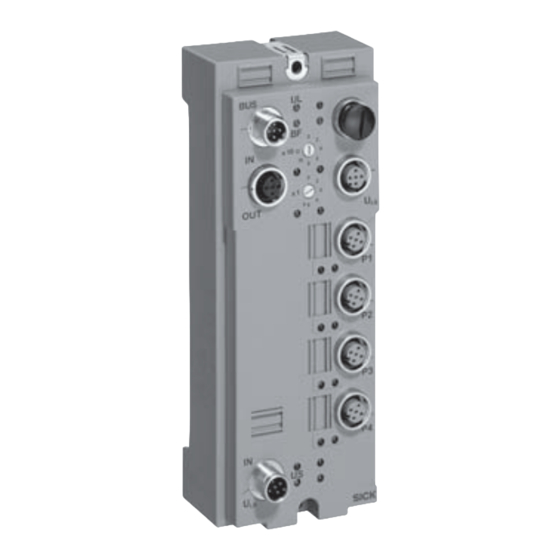
- Page 1 B E T R I E B S A N L E I T U N G / O P E R AT I N G I N S T R U C T I O N S IOLSHPB-P3104R01 Feldmodul für IO-Link Devices...
- Page 2 Betriebsanleitung IOLSHPB-P3104R01 Dieses Werk ist urheberrechtlich geschützt. Die dadurch begründeten Rechte bleiben bei der Firma SICK AG. Eine Vervielfältigung des Werkes oder von Teilen dieses Werkes ist nur in den Grenzen der gesetzlichen Bestimmun- gen des Urheberrechtsgesetzes zulässig. Eine Abänderung oder Kürzung des Werkes ist ohne ausdrückliche schriftliche Zustimmung der Firma SICK AG untersagt.
- Page 3 Block 6: IO-Link-spezifische Diagnose ..........37 Technische Daten ......................39 Maßzeichnung....................39 Pin-Belegung des PROFIBUS ................40 Pin-Belegung der Spannungsversorgung U ........... 41 Pin-Belegung der Ports ..................41 Spezifikationen....................42 2010-07-05 © SICK AG • Industrial Sensors • Deutschland • Irrtümer und Änderungen vorbehalten...
- Page 4 Diese Betriebsanleitung richtet sich an die Planer, Entwickler und Betreiber von Anlagen, welche durch einen oder mehrere Feldmodule IOLSHPB-P3104R01 betrieben werden sollen. Sie richtet sich auch an Personen, die das Feldmodul IOLSHPB-P3104R01 in eine Anlage integrieren, erstmals in Betrieb nehmen oder prüfen. Informationstiefe Diese Betriebsanleitung enthält Informationen über das Feldmodul IOLSHPB-P3104R01...
- Page 5 Das Feldmodul IOLSHPB-P3104R01 ist für dezentrale Automatisierungsaufgaben unter rauen Umgebungsbedingungen konzipiert. Das Feldmodul IOLSHPB-P3104R01 erfüllt die Schutzart IP 65 und IP 67. Mit dem Feldmodul IOLSHPB-P3104R01 wird der direkte Anschluss von IO-Link-Sensoren und -Aktoren (IOLD) mit bis zu 32 Byte IN und 32 Byte OUT ermöglicht (alle Telegrammtypen).
- Page 6 CALL (DP/V1), welcher mit PROFIBUS-I&M-Funktionen realisiert wird (Funktionsbaustein vorhanden). 2. Direkte Lese-/Schreibzugriffe auf die IOLD-Objekte über DP/V1 (Funktionsbaustein vorhanden). 3. Direkte Lese-/Schreibzugriffe auf die IOLD-Objekte über einen konfigurierbaren Prozessdatenkanal über DP/V0. © SICK AG • Industrial Sensors • Deutschland • Irrtümer und Änderungen vorbehalten 2010-07-05...
- Page 7 ACHTUNG Konfigurationsdaten Identnummer: 0x0A8C Eingabe-Adressraum: Abhängig von der Konfiguration (minimal 2 Byte, maximal 162 Byte) Ausgabe-Adressraum: Abhängig von der Konfiguration (minimal 2 Byte, maximal 162 Byte) 2010-07-05 © SICK AG • Industrial Sensors • Deutschland • Irrtümer und Änderungen vorbehalten...
- Page 8 Bit IN COM-Mode betrieben. 16 Bit OUT IOL_I/O__32/32 bit COM-Mode 32 Mit diesem Modul wird ein IOLD im „Eigene“ PD Bit IN COM-Mode betrieben. 32 Bit OUT © SICK AG • Industrial Sensors • Deutschland • Irrtümer und Änderungen vorbehalten 2010-07-05...
- Page 9 (4 Worte IN/4 Worte OUT) PD-PCP 6 words – Dieses Modul ist ein azyklischer Kanal „Virtuelles“ Modul, in den Prozessdaten. „Eigene“ PD (6 Worte IN/6 Worte OUT) 2010-07-05 © SICK AG • Industrial Sensors • Deutschland • Irrtümer und Änderungen vorbehalten...
- Page 10 IOLD über eine Prozessdatenbreite von 32 Byte IN und 32 Byte OUT verfügen kann. Zusätzlich ist die Verwendung des azyklischen Prozessdatenkanals möglich. Dafür werden 162 Byte Ein- und 162 Byte Ausgangsdaten in den PROFIBUS-Prozessdaten belegt. © SICK AG • Industrial Sensors • Deutschland • Irrtümer und Änderungen vorbehalten 2010-07-05...
- Page 11 (Default) Die Events des IOLD an Port n werden quittiert und in der PROFIBUS-Diagnose abgebildet. sperren Die Events des IOLD an Port n werden nur quittiert. 2010-07-05 © SICK AG • Industrial Sensors • Deutschland • Irrtümer und Änderungen vorbehalten...
- Page 12 Ausgangsdaten ungültig sind. Reaktion ist vom IOLD abhängig! Beachten Sie die Herstellerbe- schreibung! ACHTUNG SIO Input mit Keine Aktion IO-Link-Zugriff (IOLD hat keine Ausgangsdaten.) © SICK AG • Industrial Sensors • Deutschland • Irrtümer und Änderungen vorbehalten 2010-07-05...
- Page 13 Direct Parameter 0x18 des IOLD, siehe IOLD-Herstellerbeschreibung parameter 9 Device- Direct Parameter 0x19 des IOLD, siehe IOLD-Herstellerbeschreibung parameter 10 Device- Direct Parameter 0x1A des IOLD, siehe IOLD-Herstellerbeschreibung parameter 11 2010-07-05 © SICK AG • Industrial Sensors • Deutschland • Irrtümer und Änderungen vorbehalten...
- Page 14 1. Nur bei der Port-Betriebsart SCAN-Mode (COM-Mode) werden die „12 device specific“- Parameter nach erfolgreicher Validierung zum IOLD gesendet. 2. Nach jedem Neuanlauf der IO-Link-Kommunikationan in dieser Betriebsart werden diese Parameter gesendet. © SICK AG • Industrial Sensors • Deutschland • Irrtümer und Änderungen vorbehalten 2010-07-05...
- Page 15 Portfreigabe nach manuell freigeben Überlast Failsafe-Code alle zurücksetzen Port 1 Failsafe-Code alle zurücksetzen Port 2 Failsafe-Code alle zurücksetzen Port 3 Failsafe-Code alle zurücksetzen Port 4 2010-07-05 © SICK AG • Industrial Sensors • Deutschland • Irrtümer und Änderungen vorbehalten...
- Page 16 0xF7 Deviceparameter 8 0xF8 Deviceparameter 9 0xF9 0xFA Deviceparameter 10 0xFB Deviceparameter 11 0xFC Deviceparameter 12 Vendor_ID_1 0xD0 Vendor_ID_2 0xD1 Device_ID_1 0xDA Device_ID_2 0xDB Device_ID_3 0xDC © SICK AG • Industrial Sensors • Deutschland • Irrtümer und Änderungen vorbehalten 2010-07-05...
- Page 17 Prozessdaten des IOLD gültig sind. Dies kann verschiedene Gründe haben, z. B. war die Validierung nicht erfolgreich oder das IOLD meldet von sich aus einen Fehlerzustand. 2010-07-05 © SICK AG • Industrial Sensors • Deutschland • Irrtümer und Änderungen vorbehalten...
- Page 18 Byte 7 Die farblichen Unterlegungen der einzelnen Prozessdaten-Bytes bis hin zu farblichen Hinweis Unterlegungen einzelner Bits sollen die Zusammenhänge der Prozessdaten zu den einzelnen Modulen verdeutlichen. © SICK AG • Industrial Sensors • Deutschland • Irrtümer und Änderungen vorbehalten 2010-07-05...
- Page 19 Status der IO-Link-Verbindungen, pro Port = 3 Byte Read only Byte 1 = Portnummer Byte 2 = Status der Verbindung in DIO in Kommunikation fehlerhafte Kommunikation (kein IOL-Device) Byte 3 = reserviert (00 2010-07-05 © SICK AG • Industrial Sensors • Deutschland • Irrtümer und Änderungen vorbehalten...
- Page 20 = Betriebsart Port 2 Byte 4 = reserviert Byte 5 = Betriebsart Port 3 Byte 6 = reserviert Byte 7 = Betriebsart Port 4 Byte 8 = reserviert © SICK AG • Industrial Sensors • Deutschland • Irrtümer und Änderungen vorbehalten 2010-07-05...
- Page 21 Wert x 100 ms = Port 2 Service Response Timeout Byte 3 Wert x 100 ms = Port 3 Service Response Timeout Byte 4 Wert x 100 ms = Port 4 Service Response Timeout 2010-07-05 © SICK AG • Industrial Sensors • Deutschland • Irrtümer und Änderungen vorbehalten...
- Page 22 Ausgangsdaten des IO-Link- Read only Devices an Port 3 im COM- Mode. Die zurückgegebene Daten- länge entspricht der Daten- länge des IO-Link-Devices an Port 3 im COM-Mode. © SICK AG • Industrial Sensors • Deutschland • Irrtümer und Änderungen vorbehalten 2010-07-05...
- Page 23 Write-Request auf entsprechendem Index erzeugt. (SubIndex = 0 ) 0-254 Für den Device an Port 4 wird automatisch ein Read-/ Read/Write Write-Request auf entsprechendem Index erzeugt. (SubIndex = 0 ) 2010-07-05 © SICK AG • Industrial Sensors • Deutschland • Irrtümer und Änderungen vorbehalten...
- Page 24 Die IO-Link-Read-Service-Response-Daten des IOLD werden vom IOLM transparent auf den Responsedaten des DP/V1-Lese-Dienstes abgebildet. Bei einer negativen IO-Link Read Service Response wird eine entsprechende negative DP/V1-Lese-Dienst-Response zurückgegeben. © SICK AG • Industrial Sensors • Deutschland • Irrtümer und Änderungen vorbehalten 2010-07-05...
- Page 25 In jedem Fragment gibt es ein Dienst-Byte, das jeweils eine genaue Zuordnung des Fragmentes erlaubt. Im Folgenden sind die einzelnen Fragmente und das Dienst-Byte detailliert erläutert. 2010-07-05 © SICK AG • Industrial Sensors • Deutschland • Irrtümer und Änderungen vorbehalten...
- Page 26 Bit 3 Bit 2 Bit 1 Bit 0 Request/ Reserviert Response „0“ = Fragmenttyp: Request „10“ = Endfragment Reserviert „1“ = (Abschlussfragment) Response … Datenblock, falls erforderlich © SICK AG • Industrial Sensors • Deutschland • Irrtümer und Änderungen vorbehalten 2010-07-05...
- Page 27 Der Datenblock kann im Fehlerfall Details liefern. Von einem Fehler muss ausgegangen werden, wenn das Status-Byte einen Wert ungleich 00 annimmt. kein Fehler Fehler bei der Kommunikation Weitere Fehler (noch nicht festgelegt) 2010-07-05 © SICK AG • Industrial Sensors • Deutschland • Irrtümer und Änderungen vorbehalten...
- Page 28 Dies sind ausschließlich die Inhalte eines Objektes. Die Länge und der Umfang der Objekt- daten werden bereits zuvor durch den Parameter Länge beschrieben. Zur Verdeutlichung sollen im Folgenden Beispiele von Diensten dargestellt werden. © SICK AG • Industrial Sensors • Deutschland • Irrtümer und Änderungen vorbehalten 2010-07-05...
- Page 29 Objektes von Index 1702, SubIndex 2 des angeschlossenen Sensors. Die ersten 5 Byte- Objektdaten werden im Startfragment übertragen, die fehlenden 3 Byte folgen im zweiten und bereits letzten Fragment. Das Statusbyte zeigt an, dass die Kommunikation fehlerfrei war. 2010-07-05 © SICK AG • Industrial Sensors • Deutschland • Irrtümer und Änderungen vorbehalten...
- Page 30 Kommando „04“ ausgeführt wurde. Mit dem Status „0“ wird gezeigt, dass die Übertragung erfolgreich war. Mit einem „Clear“ können die Kommunikationsdaten wieder in ihren Ausgangszustand gesetzt werden. © SICK AG • Industrial Sensors • Deutschland • Irrtümer und Änderungen vorbehalten 2010-07-05...
- Page 31 – Synchronisierung oder Parametrierung läuft, Timeout ist abgelaufen Rot aus: – Gerät wird vom Master angesprochen und befindet sich im Zustand „Zyklischer Prozessdatenaustausch“. – Fehlende Geräteversorgung 2010-07-05 © SICK AG • Industrial Sensors • Deutschland • Irrtümer und Änderungen vorbehalten...
- Page 32 Bit 7 Bit 6 Bit 5 Bit 4 Bit 3 Bit 2 Bit 1 Bit 0 Bedeutung Block 1: PROFIBUS-Standard-Diagnose Stationsstatus 1 Stationsstatus 2 Stationsstatus 3 PROFIBUS-Master-Adresse Herstellerkennung High-Byte Herstellerkennung High-Byte © SICK AG • Industrial Sensors • Deutschland • Irrtümer und Änderungen vorbehalten 2010-07-05...
- Page 33 Länge des Blocks Device-spezifische Diagnose (Header + m IO-Link-Status) (IO-Link-Diagnose) Statusmodell: Status Message Slot-Nr. (immer 0) Status Spezifizierung (keine Spezifizierung) Status Daten-Beschreibung (IOL-StatusDataDescription) EventCode High-Byte EventCode Low-Byte 2010-07-05 © SICK AG • Industrial Sensors • Deutschland • Irrtümer und Änderungen vorbehalten...
- Page 34 Im Telegramm folgt eine erweiterte Diagnose. Angeforderte Funktion wird vom Slave nicht unterstützt. Ungültige Antwort vom Slave Fehler im Parameter- telegramm Slave ist von einem anderem Master belegt. © SICK AG • Industrial Sensors • Deutschland • Irrtümer und Änderungen vorbehalten 2010-07-05...
- Page 35 Daten des Ports sind ungültig, da ein falsches IOLD gesteckt ist. ST Pn x: 11 Daten des Ports sind ungültig, weil die IO-Link-Kommunikation nicht aktiv ist (kein oder defektes IOLD). 2010-07-05 © SICK AG • Industrial Sensors • Deutschland • Irrtümer und Änderungen vorbehalten...
- Page 36 Oberer Grenzwert überschritten ET: 8 Unterer Grenzwert überschritten ET: 9 Allgemeiner Fehler 6.2.5 Block 5: Revisionsdiagnose Zeigt die Revision der Firmware an, z. B. 0xC3 = Revision 3. © SICK AG • Industrial Sensors • Deutschland • Irrtümer und Änderungen vorbehalten 2010-07-05...
- Page 37 (voreingestellt „0“) Status-Spezifikationen: (0): keine weitere Differenzierung (1): Status gekommen (2): Status gegangen (3): reserviert Status Daten Beschreibung (Status_Type =1) IOL_Status Meldung (Status_Type =7) iPar Notification 2010-07-05 © SICK AG • Industrial Sensors • Deutschland • Irrtümer und Änderungen vorbehalten...
- Page 38 Die Bits 6 bis 7 zeigen den Event-Modus an. Zulässige Werte sind: 0 = reserviert 1 = Einzelereignis 2 = Ereignis gegangen 3 = Ereignis gekommen © SICK AG • Industrial Sensors • Deutschland • Irrtümer und Änderungen vorbehalten 2010-07-05...
- Page 39 I1/X1 … I4/X4 Port 1 bis 4 (M12-Buchsen) Spannungsversorgung OUT (Logik und IO-Link-Ports) für weitere Geräte X1/X10 Drehcodierschalter zum Einstellen der Slave-Adresse X1 für Einerstellen, X10 für Zehnerstellen 2010-07-05 © SICK AG • Industrial Sensors • Deutschland • Irrtümer und Änderungen vorbehalten...
- Page 40 Legende: A = Leitung A B = Leitung B FE = Funktionserde RS-485 = RS-485 Pegel (bidirektional) V = Spannungsversorgung PU = Pull-up PD = Pull-down © SICK AG • Industrial Sensors • Deutschland • Irrtümer und Änderungen vorbehalten 2010-07-05...
- Page 41 DC +24 V nicht belegt nicht belegt Pin-Belegung der Ports Die Pins 1, 3 und 4 bilden die IO-Link-Schnittstelle. Hinweis Abb. 6: Pin-Belegung der Ports Port (n) 2010-07-05 © SICK AG • Industrial Sensors • Deutschland • Irrtümer und Änderungen vorbehalten...
- Page 42 Längsinduktivitäten im Gerät vorhanden. Bitte beachten Sie die diesbezüglichen ACHTUNG Installationsvorschriften der PROFIBUS-Nutzerorganisation. Die Spannungen U und U an der Buchse U OUT dürfen maximal mit jeweils 2 A belastet werden. © SICK AG • Industrial Sensors • Deutschland • Irrtümer und Änderungen vorbehalten 2010-07-05...
- Page 43 DC –1 V Begrenzung induktiver Abschaltspannung integrierte Freilaufdiode je Kanal Art der Schutzschaltung nein Festigkeit gegen dauerhaft angelegte Rückspannungen maximal 100 Hz Schaltfrequenz bei einer ohmschen Nennlast 2010-07-05 © SICK AG • Industrial Sensors • Deutschland • Irrtümer und Änderungen vorbehalten...
- Page 44 This document is protected by the law of copyright, whereby all rights established therein remain with the company SICK AG. Reproduction of this document or parts of this document is only permissible within the limits of the legal determination of Copyright Law. Alteration or abridgement of the document is not permitted without the explicit written approval of the company SICK AG.
-
Page 45: Table Of Contents
Assignment of the PROFIBUS cables ..............81 Pin assignment of the power supply U ............82 Pin assignment of the ports ................82 Specifications..................... 83 2010-07-16 © SICK AG • Industrial Sensors • Germany • Subject to change without notice... -
Page 46: About This Document
IOLSHPB-P3104R01. It also addresses people who integrate the field module IOLSHPB-P3104R01 into a plant, initialise its use, or who are in charge of servicing and testing the unit. -
Page 47: On Safety
OUT (all telegramm types) in an evironment close to the station. All warranty claims against SICK AG are forfeited in the case of any other use, or altera- tions being made to devices, even as part of their mounting or installation. -
Page 48: System Description
Operating Instructions IOLSHPB-P3104R01 System description The field module IOLSHPB-P3104R01 has the following at each of the 5 pin M12 female connectors ports 1 to Port 4: one C/Q cable X(n), pin 4 one device supply L+/L-, pin 1/pin 3 and one functional earth ground FE. -
Page 49: Connection Example
Input address area: Depends on the configuration (2 bytes, minimum; 162 bytes, maximum) Output address area: Depends on the configuration (2 bytes, minimum; 162 bytes, maximum) 2010-07-16 © SICK AG • Industrial Sensors • Germany • Subject to change without notice... -
Page 50: Commissioning And Operation
32 bits OUT IOL_I/O__4/_1 byte COM mode This module is used to operate an IOLD “Own” PD 4 byte IN in COM mode. 1 byte OUT © SICK AG • Industrial Sensors • Germany • Subject to change without notice 2010-07-16... - Page 51 (4 words IN/4 words OUT) PD-PCP 6 words – This module is an acyclic channel in the “Virtual” module, process data. “Own” PD (6 words IN/6 words OUT) 2010-07-16 © SICK AG • Industrial Sensors • Germany • Subject to change without notice...
-
Page 52: Minimum Configuration
162 bytes of output data are used for this in the PROFIBUS process data. The corresponding operating mode (SCAN mode) must be parameterized for the individual ports in the global device parameters. © SICK AG • Industrial Sensors • Germany • Subject to change without notice 2010-07-16... - Page 53 The events of the IOLD at port n are acknow- ledged and mapped to the PROFIBUS diagnostics. Disable The events of the IOLD at port n are only acknowledged. 2010-07-16 © SICK AG • Industrial Sensors • Germany • Subject to change without notice...
- Page 54 Response depends on the IOLD. Please refer to the manufacturer description. WARNING SIO input with IO-Link No action (IOLD has no output data) access © SICK AG • Industrial Sensors • Germany • Subject to change without notice 2010-07-16...
- Page 55 IOLD following successful validation. 2. These parameters are sent each time IO-Link communication is restarted in this operating mode. 2010-07-16 © SICK AG • Industrial Sensors • Germany • Subject to change without notice...
-
Page 56: Example Configuration
Failsafe code port 1 Reset all Failsafe code port 2 Reset all Failsafe code port 3 Reset all Failsafe code port 4 Reset all © SICK AG • Industrial Sensors • Germany • Subject to change without notice 2010-07-16... - Page 57 Device parameter 9 0xF9 Device parameter 10 0xFA Device parameter 11 0xFB Device parameter 12 0xFC Vendor_ID_1 0xD0 Vendor_ID_2 0xD1 Device_ID_1 0xDA Device_ID_2 0xDB Device_ID_3 0xDC 2010-07-16 © SICK AG • Industrial Sensors • Germany • Subject to change without notice...
- Page 58 Note data is valid. This can be due to various reasons, e.g., validation was not completed successfully or the IOLD is indicating an error state. © SICK AG • Industrial Sensors • Germany • Subject to change without notice 2010-07-16...
- Page 59 The background color of the individual process data bytes and the background color of the Note individual bits is intended to illustrate the relationship between the process data and the individual modules. 2010-07-16 © SICK AG • Industrial Sensors • Germany • Subject to change without notice...
-
Page 60: Meaning Of The Process Data For The Io-Link Master Status
Byte 1 = Port number Byte 2 = Status of the connection in DIO in communication faulty communication (no IOL device) Byte 3 = Reserved (00 © SICK AG • Industrial Sensors • Germany • Subject to change without notice 2010-07-16... - Page 61 = Status port 2 Byte 4 = Reserved Byte 5 = Status port 3 Byte 6 = Reserved Byte 7 = Status port 4 Byte 8 = Reserved 2010-07-16 © SICK AG • Industrial Sensors • Germany • Subject to change without notice...
- Page 62 Byte 3 Value x 100 ms = Port 3 service response timeout Byte 4 Value x 100 ms = Port 4 service response timeout © SICK AG • Industrial Sensors • Germany • Subject to change without notice 2010-07-16...
- Page 63 3 in COM mode. The returned data length cor- responds to the data length of the IO-Link device at port 3 in COM mode. 2010-07-16 © SICK AG • Industrial Sensors • Germany • Subject to change without notice...
- Page 64 (SubIndex = 0 ) 0-254 A read/write request for the corresponding index is Read/Write automatically generated for the device at port 4. (SubIndex = 0 ) © SICK AG • Industrial Sensors • Germany • Subject to change without notice 2010-07-16...
-
Page 65: Io-Link Call
DP/V1 read service. In the event of a negative IO-Link read service response, a corresponding negative DP/V1 read service response is returned. 2010-07-16 © SICK AG • Industrial Sensors • Germany • Subject to change without notice... -
Page 66: Io-Link Communication Indirect Via Dp/V0
Each fragment contains a service byte, which is used for the precise assignment of the fragment. The individual fragments and the service byte are explained in detail in the following. © SICK AG • Industrial Sensors • Germany • Subject to change without notice 2010-07-16... - Page 67 Bit 1 Bit 0 Request/ Reserved Response “0” = Fragment type: Request “10” = End fragment Reserved “1” = Response … Data block, if required 2010-07-16 © SICK AG • Industrial Sensors • Germany • Subject to change without notice...
-
Page 68: Procedure For Transmission
In the event of an error, the data block can provide details. An error has occurred if the value of the status byte does not equal 00hex. No error Error during communication Additional errors (not yet defined) © SICK AG • Industrial Sensors • Germany • Subject to change without notice 2010-07-16... -
Page 69: For Vc1, The Parameters Have The Following Meaning
This is only the contents of an object. The length and scope of the object data has already been described by the length parameter. To aid understanding, the services are illustrated in the following examples. 2010-07-16 © SICK AG • Industrial Sensors • Germany • Subject to change without notice... -
Page 70: Example 1
The missing 3 bytes follow in the second fragment which is already the last. The status byte indicates that communication was error-free. © SICK AG • Industrial Sensors • Germany • Subject to change without notice 2010-07-16... -
Page 71: Example 2
The response “84” indicates that command “04” was executed. The status “0” indicates that transmission was successful. The communication data can be reset to the initial state via “Clear”. 2010-07-16 © SICK AG • Industrial Sensors • Germany • Subject to change without notice... -
Page 72: Diagnostics
– Synchronization or parameterization running, timeout elapsed Red off: – Device is addressed by the master and is in the “cyclic process data exchange” state – Device supply not present © SICK AG • Industrial Sensors • Germany • Subject to change without notice 2010-07-16... -
Page 73: Diagnostic Data Via Profibus
Block 1: PROFIBUS standard diagnostics Station status 1 Station status 2 Station status 3 PROFIBUS master address Manufacturer ID high byte Manufacturer ID low byte 2010-07-16 © SICK AG • Industrial Sensors • Germany • Subject to change without notice... - Page 74 (header + m IO-Link states) (IO-Link diagnostics) Status model: Status message Slot number (always 0) Status data description (IOL-StatusDataDescription) Status data description (IOL-StatusDataDescription) EventCode high byte EventCode low byte © SICK AG • Industrial Sensors • Germany • Subject to change without notice 2010-07-16...
-
Page 75: Block 1: Profibus Standard Diagnostics
Error in configuration telegram Telegram includes extended diagnostics Requested function not supported by slave Invalid response from slave Error in parameter telegram Slave assigned to another master 2010-07-16 © SICK AG • Industrial Sensors • Germany • Subject to change without notice... -
Page 76: Block 2: Id-Specific Diagnostics
Port data is invalid, as an incorrect IOLD is inserted. ST Pn x: 11 Port data is invalid because IO-Link communication is not active (no or faulty IOLD). © SICK AG • Industrial Sensors • Germany • Subject to change without notice 2010-07-16... -
Page 77: Block 4: Channel-Specific Diagnostics
ET: 8 Lower limit value not reached ET: 9 General error 6.2.5 Block 5: Version diagnostics Indicates the firmware version, e.g., 0xC3 = Version 3. 2010-07-16 © SICK AG • Industrial Sensors • Germany • Subject to change without notice... -
Page 78: Block 6: Io-Link-Specific Diagnostics
Status specifier: (0): No further differentiation (1): Status appeared (2): Status disappeared (3): Reserved Status data description (Status_Type =1) IOL_Status data description (Status_Type =7) iPar notification © SICK AG • Industrial Sensors • Germany • Subject to change without notice 2010-07-16... - Page 79 The bits 6 to 7 indicate the event mode. Permitted values are: 0 = Reserved 1 = Event single shot 2 = Event disappears 3 = Event appears 2010-07-16 © SICK AG • Industrial Sensors • Germany • Subject to change without notice...
-
Page 80: Technical Data
(pin 4 of the M12 female connector) Power supply OUT (logic and IO-Link ports) for additional devices X1/X10 Rotary switches to setting the slave address X1 for units, X10 for tens © SICK AG • Industrial Sensors • Germany • Subject to change without notice 2010-07-16... -
Page 81: Assignment Of The Profibus Cables
B = Cable B FE = Functional earth ground RS-485 = RS-485 level (bidirectional) V = Voltage supply PU = Pull up PD = Pull down 2010-07-16 © SICK AG • Industrial Sensors • Germany • Subject to change without notice... -
Page 82: Pin Assignment Of The Power Supply Uls
Not used Pin assignment of the ports Pins 1, 3, and 4 form the IO-Link interface. Note Abb. 6: Pin assignment of the ports Port (n) © SICK AG • Industrial Sensors • Germany • Subject to change without notice 2010-07-16... -
Page 83: Specifications
Please observe the installation instructions of the PROFIBUS user WARNING organization. The voltages UL and US at female connector ULS OUT may each only carry a maximum current of 2 A. 2010-07-16 © SICK AG • Industrial Sensors • Germany • Subject to change without notice... - Page 84 Integrated free-wheeling diode for each channel Protective circuit type Resistance to permanently applied reverse voltages 100 Hz, maximum Switching frequency with nominal ohmic load © SICK AG • Industrial Sensors • Germany • Subject to change without notice 2010-07-16...
- Page 85 E-Mail support@sick.jp E-Mail info@sickusa.com Nederlands Phone +31 (0)30 229 25 44 E-Mail info@sick.nl Norge More representatives and agencies Phone +47 67 81 50 00 in all major industrial nations at E-Mail austefjord@sick.no www.sick.com SICK AG | Waldkirch | Germany | www.sick.com...
Need help?
Do you have a question about the IOLSHPB-P3104R01 and is the answer not in the manual?
Questions and answers