Table of Contents
Advertisement
Quick Links
Advertisement
Table of Contents

Related Manuals for PCE Instruments PCE-HDM 7


Summary of Contents for PCE Instruments PCE-HDM 7
- Page 1 User Manual Electrical Tester PCE-HDM 7 User manuals in various languages (français, italiano, español, português, nederlands, türk, polski, русский, 中文) can be found by using our product search on: www.pce-instruments.com Last change: 28 November 2018 v1.0 © PCE Instruments...
-
Page 2: Table Of Contents
Capacitance measurements ....................12 5.10 Temperature measurements ...................12 Operation ..................... 13 Auto Power Off ........................13 MODE button ........................13 MAX/MIN button ......................13 Bluetooth/Flashlight button ....................13 HOLD/Backlight button ....................13 Battery and fuse replacement ............14 Warranty ....................15 Disposal ....................15 © PCE Instruments... -
Page 3: Safety Notes
Please read this manual carefully and completely before you use the device for the first time. The device may only be used by qualified personnel and repaired by PCE Instruments personnel. Damage or injuries caused by non-observance of the manual are excluded from our liability and not covered by our warranty. -
Page 4: International Safety Symbols
We expressly point to our general guarantee terms which can be found in our general terms of business. If you have any questions please contact PCE Instruments. The contact details can be found at the end of this manual. International safety symbols... -
Page 5: Safety Category Ratings
WARNING: Operation is limited to CAT II applications when the insulated tips are removed from one or both test probes. Refer to the input limits section in this manual for maximum voltage ratings. 1 – Insulated tip on 2 – Insulated tip removed © PCE Instruments... -
Page 6: Specifications
10 mV 40.00 V 0.1 V All AC voltage ranges are specified from 5 % of range to 100 % of range Input protection: 300 V AC RMS or 300 V DC Input impedance: approx. 3 kΩ © PCE Instruments... - Page 7 400.0 nF 100 pF ±(3.0 % + 5) 4.000 μF 0.001 μF 40.00 μF 0.01 μF 400.0 μF 0.1 μF 4000 μF 1 μF ±(5.0 % + 5) Input protection: 600 V AC RMS or 600 V DC © PCE Instruments...
-
Page 8: Device Description
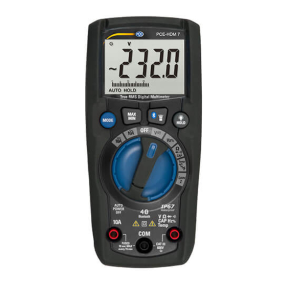
Device description Meter 1- LCD 2- MAX/MIN button 3- MODE button 4- Rotary function switch 5- 10 A input jack 6- COM input jack 7- V/Ω/ /CAP Hz%/Temp input jack 8- HOLD/Backlight button 9- Bluetooth/Flashlight button 10- Flashlight © PCE Instruments... -
Page 9: Delivery Contents
Display hold Low Z (impedance) MAX/MIN Maximum/Minimum Bluetooth Delivery contents 1 x multimeter PCE-HDM 7 1 x test lead 1 x storage bag 1 x K-type thermocouple 1 x temperature adaptor 1 x user manual 2 x AAA 1.5 batteries... -
Page 10: Measuring Functions
Touch the test leads to the circuit under test. If measuring DC voltage, touch the red test lead to the positive side of the circuit and the black test lead to the negative side of the circuit. Read the voltage on the LCD. © PCE Instruments... -
Page 11: Ac Current Measurements
Touch the test lead probes in series with the circuit being measured. Touch the red probe to the positive side of the circuit and touch the black probe to the negative side of the circuit. Apply power to the circuit. Read the current on the display. © PCE Instruments... -
Page 12: Frequency And % Duty Cycle Measurements
Touch the test lead probes to the component under test. If the component is installed in a circuit, it is best to disconnect one side before testing to eliminate interference with other devices. Read the resistance on the display. © PCE Instruments... -
Page 13: Diode Test
Ω input jack. Touch the test lead probes to the device or wire under test. A beeper will sound if the resistance is approximately 50 Ω or less and the resistance value will be shown on the LCD. © PCE Instruments... -
Page 14: Capacitance Measurements
+ side goes into the °F °C input jack. Touch the tip of the temperature probe to the object being measured. Keep the probe touching the object until the reading stabilizes (about 30 s). Read the temperature on the LCD. © PCE Instruments... -
Page 15: Operation
The backlight illuminates the LCD when the ambient light is too low to view the displayed readings. To switch on the backlight, press and hold the HOLD button until the backlight turns on. To turn it off, press and hold the HOLD button until the backlight turns off. © PCE Instruments... -
Page 16: Battery And Fuse Replacement
Always use a UL recognized fuse of the proper size and value: 10 A/600 V (5 x 20 mm) fast blow. Install the battery cover and tighten the screws. WARNING: To avoid electric shock, do not operate meter until the battery/fuse cover is securely fastened to the meter. © PCE Instruments... -
Page 17: Warranty
For countries outside the EU, batteries and devices should be disposed of in accordance with your local waste regulations. If you have any questions, please contact PCE Instruments. © PCE Instruments... - Page 18 PCE Instruments contact information Germany France Spain PCE Deutschland GmbH PCE Instruments France EURL PCE Ibérica S.L. Im Langel 4 23, rue de Strasbourg Calle Mayor, 53 D-59872 Meschede 67250 Soultz-Sous-Forets 02500 Tobarra (Albacete) Deutschland France España Tel.: +49 (0) 2903 976 99 0 Téléphone: +33 (0) 972 3537 17...
Need help?
Do you have a question about the PCE-HDM 7 and is the answer not in the manual?
Questions and answers