Table of Contents
Advertisement
Quick Links
Advertisement
Table of Contents

Related Manuals for PCE Instruments PCE-3000ULS


Summary of Contents for PCE Instruments PCE-3000ULS
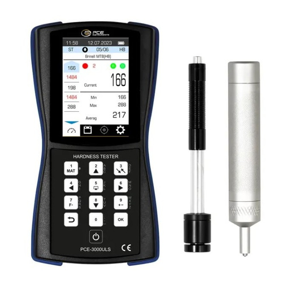
- Page 1 PCE-3000ULS HARDNESS TESTER OPERATING MANUAL...
- Page 2 This operating manual contains information on the purpose, functions, technical characteristics, the principle of operation, design, and operation of the portable hardness tester PCE-3000ULS (hereinafter - the hardness tester) and the rules of its operation, transportation and storage.
-
Page 3: Table Of Contents
CONTENT 1. DESCRIPTION OF THE HARDNESS TESTER ..........5 Purpose of the hardness tester ................5 The principle of operation of the hardness tester ..........6 Hardness tester functions ..................7 Technical specifications ..................9 Additional devices and accessories ..............12 Requirements for the controlled product ............ - Page 4 2.6.1.1 "Create scale" item ..................35 2.6.2 "Change scale" item ................... 38 2.6.2.1 Calibration adjustment ..................38 2.6.2.2 Change the calibration name ................40 2.6.2.3 Restore settings ....................41 2.6.3 Delete scale item ....................42 2.7 Custom calibration ....................43 2.7.2 Edit name ......................
- Page 5 5. PRECAUTIONS ....................64 6. RECYCLING ......................65 ATTACHMENT 1 ..................... 66...
-
Page 6: Description Of The Hardness Tester
(or additional scale) on hardness samples from the corresponding material by the user of the device or at the manufacturer, by the user's order. The PCE-3000ULS is available with pre-installed optional scales for testing a range of... -
Page 7: The Principle Of Operation Of The Hardness Tester
materials with properties other than carbon structural steels. The hardness tester is designed for use in laboratory, workshop and field conditions. The principle of operation of the hardness tester The hardness tester consists of a probe and an electronic unit for converting signals from the probe and processing the measurement results. -
Page 8: Hardness Tester Functions
Ultrasonic method The principle of operation of ultrasonic probes of the hardness tester is based on the method of measuring ultrasonic contact impedance (UCI - ultrasonic contact impedance). At the end of the metal rod, which is part of the hardness tester probe, a diamond tip is fixed. - Page 9 protection against dust and moisture. Hardness tester during measurements allows calculating the average value of a series of results of measurements and filtering incorrect measurements that are out of range. Hardness tester during measurements allows to carry out additional statistical processing of a series of results of measurements - search of the minimum, maximum values, calculation of average value, construction of graphs and display of data in the form of the table.
-
Page 10: Technical Specifications
Technical specifications Table 1.1 Measuring scale Rockwell Brinell Vickers 20 – 70 30 – 650 HB 230 – 940 HV Measuring range 10 HB – 15 HV – in range in range 90-180 HB 240-500 HV 15 HB – 20 HV – in range Accuracy 2 HRC in range 180-250 HB... - Page 11 Hardness tester probes The standard delivery set includes 2 probes – ultrasonic contact impedance and dynamic probe type "D". At the request of the consumer, additional probes may be included in the delivery set of the hardness tester. The probes are used to generate a signal that carries information about the hardness of the controlled product.
- Page 12 Table 1.2 Model Features Main application The universal probe comes standard Used for the main number of with the hardness tester. measurement tasks The probe with increased impact For coarse grained materials up to 450 energy (relative to probe "D") HB with high surface roughness.
-
Page 13: Additional Devices And Accessories
table 1.3. Table 1.3 Marking of 209 НВ (212 406 НВ (420 763 НV (63,0 103 НВ (103 НV) the probe НV) НV) (42,5 НRС) НRС) type 0,80 0,72 0,67 0,57 1,29 1,22 0,93 Е 0,80 0,72 0,67 0,57 0,23 0,16 0,13 0,09... -
Page 14: Requirements For The Controlled Product
Requirements for the controlled product The minimum recommended weight of the controlled product is in table 1.6 Table 1.6 Marking of the probe type Minimum weight, kg Minimum weight, lb. Е 0.67 If the weight of the controlled product is less than the specified - at measurements it is necessary to be guided in addition by paragraph 1.10 "Measurements on light and thin-walled products". -
Page 15: Measurement Of Specimens That Differ In Properties From Carbon Steel
If the surface roughness of the product is higher than specified, the measurements must be additionally guided by paragraph 1.11 "Work on products with high roughness". The minimum radius of curvature of the convex controlled surface is 18 mm /0.7" (for probes D, and E). -
Page 16: Requirements For Samples For Additional Adjustment Of The Hardness Tester
If the discrepancy of the results does not exceed the maximum error of the hardness tester, it means that these materials can be measured without additional calibration. If the discrepancy of the results exceeds the maximum error of the hardness tester, it is necessary to carry out additional adjustments to the hardness tester (additional calibration) for one or two samples of hardness from the controlled material. -
Page 17: Measurements On Light And Thin-Walled Products
When control specific samples it is necessary to be guided in addition by paragraph 1.10 "Measurements on light and thin-walled products". 1.10 Measurements on light and thin-walled products If the controlled product, sample, or measure of hardness does not meet the requirements of paragraph 1.7 "Requirements for the controlled product"... - Page 18 monolithic mass. In case of insufficient weight for the elimination of an additional error, it is necessary to clamp a product in massive metal vices. The weight of the vise must be greater than the minimum weight of the controlled product specified in paragraph 1.7 "Requirements for the controlled product".
-
Page 19: Measurements On Materials With High Surface Roughness
gauges of the static principle of action with the created small and ultralow loading. The reliability of the control must be assessed by comparing the readings of the hardness tester with the results of measurements by devices of the static principle of operation. -
Page 20: Hardness Measurement Of The Reinforced Surface Layers
− Work hardening - can be formed in the surface layer after turning and milling, as well as rough grinding. − Hardening - the presence of such layers (the presence, in some cases, can be determined using a hardness tester) has a much greater impact on the readings of the hardness tester than the readings of static instruments. -
Page 21: Delivery Set Of The Hardness Tester
1.14 Delivery set of the hardness tester The completeness of the supply of the hardness tester corresponds to table 1.11. The composition and availability of additional equipment are determined by the customer when ordering a hardness tester. Table 1.11 Name Qty. -
Page 22: Hardness Tester Design
1.15 Hardness tester design Functionally, the hardness tester consists of an electronic unit and a probe (see section 1.5 "Hardness testers"). The electronic unit of the hardness tester receives a signal from the electromagnetic coil of the probe, converts it into units of hardness, and displays the measurement results, statistical processing, and other functions of this hardness tester. - Page 23 . A schematic representation of the electronic unit body is shown in Figure 1.2. Figure 1.2 - Schematic representation of the body of the electronic unit On the upper-end wall of the hardness tester, there is a button for turning on the hardness tester.
- Page 24 1.16 UCI Probe handling The protective sleeve of UCI probe serves two purposes: It protects the UCI rod against damages (as distortion). Furthermore, during the measurements, it functions as a mechanical stop for the deflection of the rod. To carry out a measurement, the probe must be held perpendicular to the specimen surface.
- Page 25 Smoothly push the trigger button on the top of the probe (Fig. 1.5). Make sure that the probe does not move and secured to the surface of the controlled zone. Figure 1.5 – Pushing the trigger button of the probe After pushing the trigger button and the Impact Body hits the surface the measured hardness value will appear on the display.
-
Page 26: Operation Of Hardness Tester
2. OPERATION OF HARDNESS TESTER Before starting work, make sure that the device has no external damage and is ready for use. 2.1 Preparation for use To get started - connect the probe and turn on the device. The appliance is switched on by pressing the power button at front panel of the appliance for 1-2 seconds. -
Page 27: Hardness Tester Buttons
2.2 Hardness tester buttons In the "Measurements" tab, the buttons perform the following functions: The button allows you to select the calibration scale for a given material. The button allows you to select the measurement scale to which you want to convert values. -
Page 28: Switching The Tabs Of The Hardness Tester
2.3 Switching the tabs of the hardness tester 2.3.1 General description of hardness tester tabs items There are 4 tabs in this hardness tester: 1) Measurements (Fig. 2.1) 2) Archive (Fig. 2.2) Figure 2.2 – “Archive” tab 3) Calibration (Fig. 2.3) Figure 2.3 –... - Page 29 4) Settings (Fig. 2.4) Figure 2.4 - "Settings" tab Select the desired tab of the hardness tester by briefly pressing the button . When pressed, the icons are highlighted in blue (Fig. 2.5). Figure 2.5 - Select the desired item in the hardness tester tab Once the desired tab is selected, you need to press the button to enter it.
-
Page 30: Measurement Tab
2.4 Measurement tab In the measurements tab you can choose: • calibration on a given scale, • scales for measurement conversion, • probe directions, • a number of measurements in series. 2.4.1 Selection of calibration scale To select the calibration according to a given scale, press the button , then the calibration selection window will open (Fig. -
Page 31: Selecting The Scale For Measurement Conversion
2.4.2 Selecting the scale for measurement conversion To select the scale to convert the measurement, press the button . The required window will open (Fig. 2.7). Use the buttons to select the desired value of the scale, then press the button . -
Page 32: Choice Of Number Of Measurements
2.4.4 Choice of number of measurements To select the number of measurements, press the button . In the window, use the buttons to enter the required number of measurements, but not more than 20. Then press the button . To return to the "Measurements"... - Page 33 Measurements are sorted by date and time. Use the buttons to select the desired date, and use the buttons to select the desired value of the time when the measurement was made. After the desired value is selected, press the button .
-
Page 34: Calibration Tab
2.6 Calibration tab To enter the "Calibration" tab, press the button to select the appropriate icon on the screen of the hardness tester (Fig. 2.13) and press the button . After that, the "Calibration" tab will be entered (Fig. 2.14) Figure 2.13 - Calibration tab icon Figure 2.14 - "Calibration"... - Page 35 the password will appear, enter the password using the buttons (Fig. 2.15). After entering the password, a window will open with three options: "Create scale", "Change scale" and "Delete scale" (Fig. 2.16). Figure 2.15 - Service password entry window Figure 2.16 - Items in the standard calibration...
-
Page 36: Create Scale" Item
2.6.1.1 "Create scale" item Use the buttons to select "Create scale" and click in the window that opens, the user will be prompted to enter the calibration name (Fig. 2.17). Figure 2.17 - Enter the calibration name Use the buttons to enter the calibration name and press the button The next step is to select the hardness measurement scale (Fig. - Page 37 Then a window will open where you need to enter the number of hardness measures for calibration (Fig. 2.19), use the buttons to enter the desired number of measures and press Figure 2.19 - Enter the number of hardness measures for calibration A window will appear (Fig.
- Page 38 Figure 2.20 - Calibration of the device on calibration measures Figure 2.21 - Enter the specific value of the calibration measure After performing these steps, a calibration completion message will be displayed. In order to exit the process of creating a new calibration, you need to press the button , a dialog box will appear (Fig.
-
Page 39: Change Scale" Item
Figure 2.22 - Exit the calibration mode 2.6.2 "Change scale" item To change an already saved scale, use the buttons to select "Change scale" and press . The following items will appear in the window (Fig. 2.23): "Adjustment", "Change name", "Restore settings". Figure 2.23 - Scale change window 2.6.2.1 Calibration adjustment To adjust the calibration, use the buttons... - Page 40 Figure 2.24 - Selecting the item "Adjustment" In the window that opens (Fig. 2.25) - use the buttons to select the desired calibration and press Figure 2.25 - Select the desired calibration scale Then, using the buttons in the window (Fig. 2.26), enter the number of adjustment points and press .
-
Page 41: Change The Calibration Name
Figure 2.26 - Enter the number of points (measures of hardness) adjustment Figure 2.27 - Value adjustment Press , repeat the measurement on another sample, adjust the hardness value, and press the button . The calibration will then be adjusted. 2.6.2.2 Change the calibration name To change the name of the calibration, use the buttons , to select "Change... -
Page 42: Restore Settings
Figure 2.28 - Calibration name change window Use the buttons to enter the desired calibration name and press . Then, by pressing the button you can return to the "Calibration" tab. 2.6.2.3 Restore settings Select "Restore settings" (Fig. 2.24) and press . -
Page 43: Delete Scale Item
2.6.3 Delete scale item To delete the calibration scale, use the buttons , to select "Delete scale" and press the button (Fig. 2.16). In the tab that opens, select the scale you want to delete and click (Fig. 2.30). After that the window of confirmation of removal of calibration will open (fig. -
Page 44: Custom Calibration
2.7 Custom calibration Custom calibration is intended for the user to create their calibrations on their materials. The user can add new calibrations for different materials and adjust the values of custom calibrations already created by him. To do this, use the buttons to select "Custom"... - Page 45 Figure 2.35 - Enter the calibration name Use the buttons o enter the calibration name and press the button The next step is to select the hardness measurement scale (Fig. 2.36), use the buttons to select the desired hardness measurement scale, and press Figure 2.36 - Choice of hardness measurement scale...
- Page 46 Then a window will open where you need to enter the number of hardness measures for calibration (Fig. 2.37), use the buttons to enter the desired number of measures, and press Figure 2.37 - Enter the number of measures to calibrate A window will appear (Fig.
- Page 47 Figure 2.39 - Enter the specific value of the calibration measure After performing these steps, a calibration completion message will be displayed. To exit the process of creating a new calibration, you need to press a button , on an empty line of name or number, and a dialog box will appear (Fig.
-
Page 48: Edit Name
2.7.2 Edit name To change the calibration user name, use the buttons to select "Edit name" and press the button (Fig. 2.34). In the tab that opens (Fig. 2.41), use the buttons to select the calibration whose name you want to change and press . -
Page 49: Delete Scale Item
2.7.3 Delete scale item To delete a custom calibration scale, use the buttons , to select "Delete scale" and press the button (Fig. 2.43). In the tab that opens, select the scale you want to delete and click (Fig. 2.44). Figure 2.43 - Items in the custom calibration Figure 2.44 - View tab "Delete scale"... -
Page 50: One Point Calibration
2.8 One point calibration If the device is calibrated to standard measures, for example, carbon steel 35, the readings on products made of similar steels, with the same heat treatment - will not differ much. But the values of the hardness of alloy steels and other alloys, which have a completely different chemical composition compared to standard measures - will differ significantly. - Page 51 Figure 2.47 - Password entry window Figure 2.48 - Calibration selection You will then be prompted to enter a new calibration name. Use the buttons to enter the new calibration name and press the button A window will appear (Fig. 2.49), where you should take a series of measurements. After a series of strikes press the button , and in the window that opens (Fig.
- Page 52 Figure 2.49 - One point calibration of the Figure 2.50 - Enter the specific value of the device calibration measure After performing these actions, a message will be displayed stating that the calibration has been adjusted, and it will be saved in the "Custom" section under a new name. To exit the process of creating a calibration on one point, you need to press the button , a dialog box will appear (Fig.
-
Page 53: Settings Tab
2.9 Settings tab To enter the "Settings" tab, press the button to select the appropriate icon on the screen of the hardness tester (Fig. 2.52) and press the button . After that, enter to the "Settings" tab (Fig. 2.53). Figure 2.52 - Settings tab icon Figure 2.53 - Settings tab 2.9.1 Description of the "Settings"... -
Page 54: Date And Time
2.9.2 Date and time To enter the tab, use the buttons to select "Date and time" and press window will open (Fig. 2.54), where you need to set the date using the keyboard, then press the button , then you need to set the time and press . -
Page 55: Probe Type
Figure 2.55 - "Save the series" tab window 2.9.4 Probe type On this tab, you can select from four different probe types: Type D probe, G probe, E probe, and UCI probe. To enter the tab, use the buttons to select "Sensor type" and press window will open (Fig. -
Page 56: Language
2.9.5 Language In this tab, you can choose English, Russian or Ukrainian language. To change the interface language, use the buttons to select "Language" and press the button , in the window (Fig. 2.57), use the buttons to select the desired language and press the button Figure 2.57 - "Language"... -
Page 57: Change Password
2.9.7 Change password This tab allows you to change the user password. To change the password using the buttons select "Change password" and press the button , in the window, using the keyboard, enter the old password (Fig. 2.59). Then the window for changing the password will open (Fig. 2.60), where you should enter a new password using the keyboard, press the button , then re-enter the new password and press... -
Page 58: Sound Settings
2.9.8 Sound settings In this tab, the user can enable or disable audible confirmation of actions. To turn the audible confirmation on or off, use the buttons to select "Sound Settings" and press the button . In the window (Fig. 2.62), use the buttons select "Yes"... -
Page 59: Usb Settings
Figure 2.62 - "Auto-shutdown time" tab window 2.9.10 USB settings In this tab, the user can enable or disable the USB port to connect to a PC. Figure 2.63 - "USB Settings" tab window To turn the USB port on or off, use the buttons to select "USB Settings"... -
Page 60: Service Menu
2.9.11 Service menu This tab is intended for service of the device by service specialists of the manufacturer (Fig. 2.64). Figure 2.64 - "Service menu" tab window 2.9.12 Statistics This tab is designed to change the search mode for measurements that are not taken into account (rejected). -
Page 61: About The Device
2.9.13 About the device In this tab, the user can view information about the device (Fig. 2.66). The user can see: the gain of the probe, the coefficient of standard deviation, the error after calibration at one point, and the firmware version. Figure 2.66 - "About the device"... -
Page 62: Marking Of The Hardness Tester
2.10 Marking of the hardness tester On the front panel of the device is a symbol of the device with the trademark of the manufacturer. On the rear panel of the electronic unit is a plate indicating: • name of the manufacturer; •... -
Page 63: Maintenance
3. MAINTENANCE Checking the technical condition of the hardness tester is carried out at least once a year in the following sequence: − check the completeness of the hardness tester according to clause 1.14 "Delivery set of the hardness tester"; −... -
Page 64: Transportation And Storage
4. TRANSPORTATION AND STORAGE Packed instruments can be transported by any rail, road, sea, or air transport provided the following conditions are met: - transportation is carried out in factory packaging; - there is no direct exposure to moisture; - the temperature does not exceed -50 ° C to +50 ° C / -58 ° F to 122 ° F - humidity does not exceed 95% at temperatures up to 35 °... - Page 65 5. PRECAUTIONS A hardness tester is a technically complex measuring device that requires careful handling. It must be protected from: • shocks, loads that can lead to mechanical damage to the hardness tester; • exposure to chemically aggressive environments; • ingress of liquids; •...
- Page 66 6. RECYCLING The hardness tester does not contain in its design any dangerous or poisonous substances that can harm human health or the environment and do not pose a threat to life, health of people and the environment at the end of their service life. In this regard, the recycling of the product can be made according to the rules for the disposal of general industrial waste.
- Page 67 ATTACHMENT 1 MAINTENANCE PROTOCOL Next The cause of Mark of Service № Date Type Maintenance the fault functionality center (recommended)
Need help?
Do you have a question about the PCE-3000ULS and is the answer not in the manual?
Questions and answers