Advertisement
Quick Links
PCE Americas Inc.
PCE Instruments UK Ltd.
711 Commerce Way
Units 12/13
Suite 8
Southpoint Business Park
Jupiter
Ensign way
FL-33458
Hampshire / Southampton
USA
United Kingdom, SO31 4RF
From outside US: +1
From outside UK: +44
Tel: (561) 320-9162
Tel: (0) 2380 98703 0
Fax: (561) 320-9176
Fax: (0) 2380 98703 9
info@pce-americas.com
info@pce-instruments.com
www.pce-instruments.com/english
www.pce-instruments.com
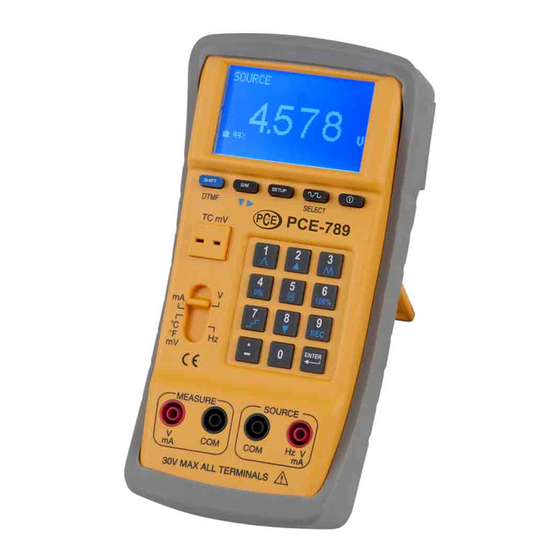
Manual
Current Calibrator PCE-789
Version 1.0
Date of creation: 17.08.2016
Date of last change: 02.09.2016
Advertisement

Related Manuals for PCE Instruments PCE-789


Summary of Contents for PCE Instruments PCE-789
- Page 1 PCE Americas Inc. PCE Instruments UK Ltd. 711 Commerce Way Units 12/13 Suite 8 Southpoint Business Park Jupiter Ensign way FL-33458 Hampshire / Southampton United Kingdom, SO31 4RF From outside US: +1 From outside UK: +44 Tel: (561) 320-9162 Tel: (0) 2380 98703 0...
-
Page 2: Table Of Contents
Please read this manual carefully and completely before you use the device for the first time. The device may only be used by qualified personnel and repaired by PCE Instruments personnel. There is no warranty of damages or injuries caused by non-observance of the manual. -
Page 3: Specification
Do not expose the device to extreme temperatures, direct sunlight, extreme humidity or wetness. The opening of the case should only be done by the qualified personnel of the PCE Instruments. The instrument should never be placed with the user interface (e.g. - Page 4 Manual mA (measuring function) Measuring range Resolution Reading accuracy 1μA -4mA to -0,005mA ±0.1% / ± 5dgts 1μA 0,005mA to 4mA ±0.1% / ± 5dgts 4mA to 20mA 1μA ±0.1% / ± 5dgts 1μA 20mA to 24mA ±0.1% / ± 5dgts When the measured value is smaller than 5, 0 is displayed.
- Page 5 Manual Temperature, Thermocouples (sources and measuring function, 0.1 °C & 0.1 °F resolution, internal cold junction compensation (CJC), accuracy of the thermocouple not included, 3 minutes after inserting the thermocouples) °C °F Measuring range Accuracy Measuring range Accuracy -200 to -150 -382 to -238 -150 to 0 -238 to 32...
-
Page 6: System Description
Manual Duty cycle (%, square wave, 10 Vpp, 0.3 ~ 20kHz) Measuring range Resolution Rise time of Vpp Fall time of Vpp 10μs maximum 15μs maximum, 0 to 100% 5μs typical 7.5μs typical DTMF (Hz) Measuring range Resolution Reading accuracy 0.3 to 99.999 0.1 Hz 0.002 Hz... - Page 7 Manual Operating Manual Voltage source a) 3V ~ 15V (1) Turn on the device and push the slide switch to "V" (2) Press the S / M button to select the SOURCE (output) mode. (Press SETUP once to save this as the initial setting.) (3) Enter a voltage value (incl.
- Page 8 1. Do not connect any voltage potential or a live circuit to the SOURCE jacks in order to avoid the damage of PCE-789. 2. If there is short circuit or an overvoltage at the output jacks, the PCE-789 cannot show any correct voltage value. Disconnect the device and check, whether an OUTPUT ERROR symbol is displayed.
- Page 9 1. Do not connect any current carrying conductor or a loaded circuit to the SOURCE jacks in order to avoid the damage of PCE-789. 2. If there is short circuit or an overload at the output jacks, the PCE-789 cannot show any correct current value. Disconnect the device and check, whether an OUTPUT ERROR symbol is displayed.
- Page 10 (3) If 100 has been typed by the user and ENTER pressed, the display shows the following values: 100.00KW (on the main display) and 20.000mA (the current value output by the PCE-789). (4) If the ramp function is used, the display shows 0 ~ 100KW instead of 4 ~ 20mA.
- Page 11 1. Do not connect any current carrying conductor or a loaded circuit to the TC jacks in order to avoid the damage of PCE-789. 2. If there is a short circuit or an overload at the output jacks, the PCE-789 cannot show any correct voltage value. Disconnect the device and check, whether an OUTPUT ERROR symbol is displayed.
- Page 12 Manual c) Setup Details 1. Press S/M to select the desired option. 2. The desired value can be entered when the appropriate option is in a reverse black / white mode. 3. C.J.COMP.: here a value for CJC can be set (the standard value is 0.0°C. Compensation between -5°c and +5°C corresponding to the ideal output values can be set).
- Page 13 1. Do not connect any current carrying conductor or a loaded circuit to the SOURCE jacks in order to avoid the damage of PCE-789. 2. If there is a short circuit or an overload at the output jacks, the PCE-789 cannot show any correct voltage value. Disconnect the device and check, whether an OUTPUT ERROR symbol is displayed.
- Page 14 Manual (5) Waveform selection: here you can select between sine signal, rectangular signal, triangular signal, clipped sine signal and custom signal. (6) Custom signal: first, the user must compile a waveform in the PC und transfer this to the PCE- 789 (details can be found in the software manual).
- Page 15 1. Do not connect any current carrying conductor or a loaded circuit to the SOURCE jacks in order to avoid the damage of PCE-789. 2. If there is a short circuit or an overload at the output jacks, the PCE-789 cannot show any correct voltage value. Disconnect the device and check, whether an OUTPUT ERROR symbol is displayed.
- Page 16 (4) Then connect the test leads or the crocodile clamps to the object to me measured. (5) The display of the PCE-789 shows the measured voltage value. (6) In order to use the data logger function, read the chapter “Data Logging”.
- Page 17 Manual Warning: 1. Do no measure voltage over 30V at the MEASURE jacks to avoid the damage of the PCE-789. Always make only one measurement at the same time and connect only the sockets required for this. Disconnect all the unused sockets. Connect the measuring cable only with one socket type (SOURCE or MEASURE or TC).
- Page 18 4mA and "100KW" for 20mA were set in the SETUP menu). (3) If 100 has been typed by the user and ENTER pressed, the display shows the following values: 100.00KW (on the main display) and 20.000mA (the current value output by the PCE-789).
- Page 19 (3) Select a thermocouple in the Setup menu. (4) Connect the thermocouple to the TC/mV jack. (5) Finally, connect the thermocouple cable to the measured object. (6) The display of the PCE-789 shows now the temperature of the measure object.
- Page 20 1. The measurement result is displayed with 5 digits (incl. digits after the decimal point). Warning: 1. Do no measure voltage over 30V at the MEASURE jacks to avoid the damage of the PCE-789. Always make only one measurement at the same time and connect only the sockets required for this.
- Page 21 Manual c) Setup Details (1) Press S/M to select the desired option. (2) The desired value can be entered when the appropriate option is in a reverse black / white mode. (3) C.J.COMP.: here a value for CJC can be set (the standard value is 0.0°C. A compensation between -5°c and +5°C corresponding to the ideal output values can be set).
- Page 22 Manual b) Ramp Function Press the SHIFT and the display shows you various functions in the lower left part. See the following table. Functions Ramp sampling 1% 2% … 100% 99% … 2% 1% Manual multi-stage sampling (gradual increase) One press of this button: +25% (up to 100%) Fast ramp sampling 4% 8% …...
- Page 23 Manual Example of Connecting the Measuring Cable (for fast and multistage sampling) Connection for fast ramp sampling Connection for multistage sampling...
- Page 24 Manual Ramp Function for Current Sampling (as source) a) Setup instructions (1) Press SETUP to enter the SETUP menu. (2) V 0%: sets the current starting value. (3) V 100%: sets the current end value. Note: 1. The users may enter maximum 5 digits. 2.
- Page 25 Manual c) Example of Connecting the Measuring Cable (for fast and multistage sampling) Connection for fast ramp sampling...
- Page 26 Manual Connection for multistage sampling Ramp Function for Temperature Values (as source) a) Setup Instructions (1) Press SETUP to enter the SETUP menu. (2) TC 0%: sets the temperature starting value. (3) TC 100%: sets the temperature end value.
- Page 27 1. The users may enter maximum 5 digits. 2. If you enter a temperature value (incl. digits after the decimal point), and then press ENTER, the PCE-789 outputs this parameter value. 3. If the output value is < 0, please, enter the minus first.
- Page 28 Manual c) Example of Connecting the Measuring Cable (for fast and multistage sampling) Connection for fast ramp sampling Connection for multistage sampling...
- Page 29 Manual Data Logging Use of the Data Logger The data logger functions are available for all measuring ranges, except Hz. a) Instructions (1) The user can set the value for SAMPLE and FILE NAME only in V measuring ranges. These settings are automatically taken for the other measuring ranges (mA, …).
- Page 30 Manual Storing Single Value a) Instructions for Data Logging (1) The user can set the value for SAMPLE and FILE NAME only in V measuring range. These settings are automatically for the other measurement ranges (mA, ...). (2) Press SETUP to enter the setup menu. (3) SAMPLE: Set the sample time for the data log to "0".
- Page 31 PCE-789 (see the details in the software manual). Remote Control via PC 1. The baud rate between PC and PCE-789 is 460800Bps. 2. The following table shows the PC-keys corresponding to the PCE-789. Maintenance and Cleaning Charging the battery pack 1.
- Page 32 In order to comply with the EU directive 2012/19/EU we take our devices back. We either re-use them or give them to a recycling company which disposes of the devices in line with law. If you have any questions, please contact PCE Instruments. Annex 1 ASCII-Table...
- Page 33 Manual ω > △ 千 Г Σ 万 Ф 元 Ω 丹...
-
Page 34: Pce Americas
Manual 11 Contact If you have any questions about our range of products or measuring instruments please contact PCE Instruments. 11.1 PCE Instruments UK By post: PCE Instruments UK Ltd. Units 12/13 Southpoint Business Park Ensign Way, Southampton Hampshire United Kingdom, SO31 4RF...
Need help?
Do you have a question about the PCE-789 and is the answer not in the manual?
Questions and answers