Table of Contents
Advertisement
Quick Links
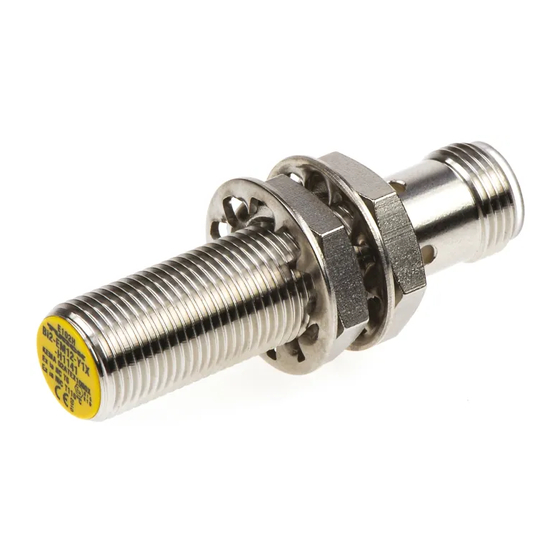
Inductive sensor
BI2-M12-Y1X-H1141
Type code
Ident no.
Rated switching distance Sn
Mounting conditions
Assured switching distance
Correction factors
Repeatability
Temperature drift
Hysteresis
Output function
Switching frequency
Voltage
Non-actuated current consumption
Actuated current consumption
Approval acc. to
Internal capacitance (C
) / inductance (L
i
Device designation
Construction
Dimensions
Housing material
Active area material
Max. tightening torque housing nut
Connection
Vibration resistance
Shock resistance
Protection class
MTTF
Switching state
1 / 5
Hans Turck GmbH & Co.KG ñ D-45472 Mülheim an der Ruhr ñ Witzlebenstraße 7 ñ Tel. 0208 4952-0 ñ Fax 0208 4952-264 ñ more@turck.com ñ www.turck.com
BI2-M12-Y1X-H1141
40102
2 mm
flush
ð (0,81 x Sn) mm
St37 = 1; Al = 0.3; stainless steel = 0.7; Ms = 0.4
ð 2 % of full scale
ð ± 10 %
1...10 %
2-wire, NAMUR
5 kHz
Nom. 8.2 VDC
ï 2.1 mA
ð 1.2 mA
KEMA 02 ATEX 1090X
)
150 nF / 150 µH
i
É II 1 G Ex ia IIC T6 Ga/II 1 D Ex ia IIIC T115 °C
Da
(max. U
= 20 V, I
i
threaded barrel, M12 x 1
52 mm
Metal, CuZn, chrome-plated
Plastic, PA
10 Nm
flange connector, M12 x 1
55 Hz (1 mm)
30 g (11 ms)
IP67
6198 years acc. to SN 29500 (Ed. 99) 40 °C
LED yellow
= 20 mA, P
= 200 mW)
i
i
■
ATEX category II 1 G, Ex zone 0
■
ATEX category II 1 D, Ex zone 20
■
SIL2 as per IEC 61508
■
Threaded barrel, M12 x 1
■
Chrome-plated brass
■
DC 2-wire, nom. 8.2 VDC
■
Output acc. to DIN EN 60947-5-6 (NA-
MUR)
■
M12 x 1 male connector
Wiring Diagram
Functional principle
Inductive sensors detect metal objects con-
tactless and wear-free. For this, they use a
high-frequency electromagnetic AC field that
interacts with the target. Inductive sensors
generate this field via an RLC circuit with a
ferrite coil.
Advertisement
Table of Contents

Related Manuals for turck BI2-M12-Y1X-H1141


Summary of Contents for turck BI2-M12-Y1X-H1141
- Page 1 6198 years acc. to SN 29500 (Ed. 99) 40 °C Switching state LED yellow 1 / 5 Hans Turck GmbH & Co.KG ñ D-45472 Mülheim an der Ruhr ñ Witzlebenstraße 7 ñ Tel. 0208 4952-0 ñ Fax 0208 4952-264 ñ more@turck.com ñ www.turck.com...
- Page 2 6 x Sn Diameter of the active area B Ø 12 mm 2 / 5 Hans Turck GmbH & Co.KG ñ D-45472 Mülheim an der Ruhr ñ Witzlebenstraße 7 ñ Tel. 0208 4952-0 ñ Fax 0208 4952-264 ñ more@turck.com ñ www.turck.com...
- Page 3 Mounting bracket for threaded barrel devices; material: Stain- less steel A2 1.4301 (AISI 304) 3 / 5 Hans Turck GmbH & Co.KG ñ D-45472 Mülheim an der Ruhr ñ Witzlebenstraße 7 ñ Tel. 0208 4952-0 ñ Fax 0208 4952-264 ñ more@turck.com ñ www.turck.com...
- Page 4 PVC, black; cULus approval; other cable lengths and qualities available, see www.turck.com 4 / 5 Hans Turck GmbH & Co.KG ñ D-45472 Mülheim an der Ruhr ñ Witzlebenstraße 7 ñ Tel. 0208 4952-0 ñ Fax 0208 4952-264 ñ more@turck.com ñ www.turck.com...
- Page 5 Repairs are not possible. The approval expires if the device is repaired or modified by a person other than the manufacturer. The most important data from the approval are listed. 5 / 5 Hans Turck GmbH & Co.KG ñ D-45472 Mülheim an der Ruhr ñ Witzlebenstraße 7 ñ Tel. 0208 4952-0 ñ Fax 0208 4952-264 ñ more@turck.com ñ www.turck.com...
Need help?
Do you have a question about the BI2-M12-Y1X-H1141 and is the answer not in the manual?
Questions and answers