Table of Contents
Advertisement
Advertisement
Table of Contents

Related Manuals for Omron Quattro 650H


Summary of Contents for Omron Quattro 650H
- Page 1 Quattro 650H/650HS/800H/800HS User’s Guide I597-E-05...
- Page 2 Copyright Notice The information contained herein is the property of Omron Adept Technologies, Inc., and shall not be reproduced in whole or in part without prior written approval of Omron Adept Technologies, Inc. The information herein is subject to change without notice and should not be construed as a commitment by Omron Adept Technologies, Inc.
-
Page 3: Table Of Contents
Table of Contents Chapter 1: Introduction 1.1 Quattro Robots, Product Description Controllers Sizes and Materials Major Differences between Quattro H and HS Robots eAIB Quattro Robot Base Inner Arms Ball Joints, Outer Arms Platforms SmartController EX 1.2 Installation Overview 1.3 How Can I Get Help? Related Manuals Chapter 2: Safety 2.1 What to Do in an Emergency / Abnormal Situation... - Page 4 Table of Contents Chapter 3: Robot Installation - H 3.1 Transport and Storage 3.2 Unpacking and Inspecting the Equipment Before Unpacking Upon Unpacking Unpacking 3.3 Repacking for Relocation 3.4 Environmental and Facility Requirements 3.5 Mounting Frame Frame Orientation Frame Construction Robot-to-Frame Considerations Mounting Gussets...
- Page 5 Table of Contents Installing the Cable Inlet Box 4.7 Mounting the Robot Base Robot Orientation Mounting Surfaces Mounting Options Mounting Procedure from Above the Frame Mounting Procedure from Below the Frame Install Mounting Hardware 4.8 Attaching the Outer Arms and Platform Clocking the Platform to the Base Attaching the Outer Arms 4.9 Mounting the Front Panel...
- Page 6 Table of Contents Robot-Mounted Equipment Configuration 5.11 Installing User-Supplied Safety Equipment Emergency Stop Circuits Remote Manual Mode User Manual/Auto Indication User High Power On Indication Remote High Power On/Off Control High Power On/Off Lamp Remote Front Panel or User-Supplied Control Panel Usage Remote Pendant Usage Chapter 6: System Operation 6.1 Robot Status Display Panel...
- Page 7 Torque and Rotation Limits Payload Mass vs. Acceleration Payload Inertia vs. Acceleration 8.6 Stopping Times and Distances 8.7 Robot Mounting Frame, Quattro 650H Robot Chapter 9: Maintenance - H 9.1 Periodic Maintenance Schedule 9.2 Warning Labels 9.3 Checking Safety Systems 9.4 Checking Robot Mounting Bolts...
- Page 8 Table of Contents 9.13 Replacing Outer Arm Spring Assemblies Removing Outer Arm Spring Assemblies Installing Outer Arm Spring Assemblies 9.14 Changing the Lamp in the Front Panel High-Power Indicator Chapter 10: Maintenance - HS 10.1 Cleaning Water Shedding Wash-Down Chemical Compatibility 10.2 Warning Labels 10.3 Periodic Maintenance 10.4 Checking Safety Systems...
- Page 9 Table of Contents Chapter 11: Robot Cleaning/ Environmental Concerns- H 11.1 Ambient Environment Humidity Temperature 11.2 Cleaning Caustic Compatibility Water Shedding Wipe-Down 11.3 Cleanroom Classification 11.4 Design Factors Robot Base and Components Inner Arms Ball Joints Outer Arms Springs Platforms 11.5 Installing Cable Seal Kit Overview Installation Procedure...
- Page 10 Updated unpacking instructions with new crate con- figuration. Updated recommended power supply model numbers. Updated images of platform to show Omron Adept logo. Changed ACE software disk to ACE software media. Updated pictures to show painted inner arms. Add note to firmly hold end of arm tooling when attach- ing to the flange to prevent damage to platform belt.
- Page 11 Revision Date Revised Content Code Many changes to Chapter 5: System Installation includ- ing new and improved figures, content removal and addi- tions. Operating temperature range, changed to 1 to 40°C from previously noted 5 to 40°C. Added red CAD version of status codes to Status Panel Fault Codes section in chapter 5.
-
Page 13: Chapter 1: Introduction
Quattro 650H (Anodized Aluminum & SS) and Quattro 650HS (SS) Quattro 800H (Anodized Aluminum & SS) and Quattro 800HS (SS) The Quattro 650H and 800H are available with anodized aluminum or stainless steel (SS) platforms, and anodized aluminum outer arm spoons. The eAIB and cable box used with the two H models are anodized aluminum. - Page 14 1.1 Quattro Robots, Product Description Table 1-1. Quattro H/HS Differences Standard (650H/800H) HS (650HS/800HS) USDA Accepted (Meat and Poultry) IP rating IP65, Option IP66, Standard P30 Platform, no rotation Hard-anodized or Stainless Steel Stainless Steel (SS) (SS) P31 Platform, 46.25° Hard-anodized or SS P32 Platform, 92.5°...
-
Page 15: Eaib
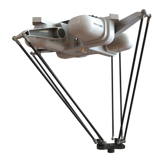
Chapter 1: Introduction Figure 1-1. Major Robot Components, Isometric View (650HS shown) Callout Description Callout Description Mounting Pads Motor Cover eAIB Outer Arms Cable Inlet Box Platform Base Ball Joints (Spring Assemblies not shown) Inner Arm eAIB The power amplifiers for the Quattro robot are embedded in the base of the robot. This amp- lifier section is known as the Amplifiers in Base (eAIB) distributed motion control platform, and provides closed-loop servo control of the robot amplifiers, as well as robot I/O. -
Page 16: Quattro Robot Base
1.1 Quattro Robots, Product Description 8 kHz servo rate to deliver low positional errors and superior path following Sine-wave commutation to lower cogging torque and improve path following Digital feed-forward design to maximize efficiency, torque, and velocity Temperature sensors on all amplifiers and motors for maximum reliability and easy troubleshooting Hardware-based E-Stop and Teach Restrict controls These are for improved safety relative to European standards implemented in 2012. -
Page 17: Platforms
Chapter 1: Introduction each socket accepts the ball joint studs on the inner arms and platform, and allows for approx- imately ± 60° of relative motion. No ball joint lubrication is required. Figure 1-3. Quattro Ball Joint Assembly, Quattro HS Robot shown Callout Description Callout... - Page 18 1.1 Quattro Robots, Product Description The suffix on the part numbers that follow indicates the finish or material of the platform. Refer to Materials and Finishes on page 20. P31 Platform (P/N 09503-xxx) The P31 platform has a rotation range of ±46.25°. The tool flange is machined into one of the pivot links.
- Page 19 Chapter 1: Introduction Figure 1-5. P30 Platform Figure 1-6. P32 Platform NOTE: The only visible difference between the P32 and P34 platforms is the model number, and the two or four dots immediately below that number. Two dots designate a P32 platform. 09955-000 Rev.
-
Page 20: Smartcontroller Ex
1.1 Quattro Robots, Product Description Materials and Finishes Platforms are available in: Aluminum with hard-anodized finish Stainless steel The following table shows which materials and finishes are compatible with which robots: 650H 650HS 800H 800HS Part Number Hard XXXXX-000 Anodized Stainless XXXXX-200 Steel... -
Page 21: Installation Overview
Chapter 1: Introduction Figure 1-7. SmartController EX Refer to the SmartController EX User’s Guide for SmartController specifications. 1.2 Installation Overview The system installation process is summarized in the following table. Also, refer to System Installation on page 71. NOTE: For multi-robot installations, see the Single and Multiple Robot Con- figuration Guide. -
Page 22: How Can I Get Help
Install optional equipment, including end-effectors, End-Effectors on page 129. user air and electrical lines, external equipment, etc. 1.3 How Can I Get Help? For support or service, contact your local Omron support. Refer to additional information sources on our corporate website: http://www.ia.omron.com Related Manuals This manual covers the installation, operation, and maintenance of an Quattro robot system. -
Page 23: Chapter 2: Safety
Chapter 2: Safety 2.1 What to Do in an Emergency / Abnormal Situation Press the E-Stop button (a red push-button on a yellow background) and then follow the internal procedures of your company or organization for a robot emergency situation. If a fire occurs, use a type D extinguisher: foam, dry chemical, or CO Releasing the Brakes In case of an emergency or abnormal situation, the platform can be manually moved without... -
Page 24: Dangers, Warnings, And Cautions
2.2 Dangers, Warnings, and Cautions Enable power through ACE software installed on your PC Press the green ROBOT POWER button on the Front Panel Press the ROBOT POWER button on the Pendant Once the motors are enabled, the robot will wait two seconds and then resume commanded motion, if there is adequate space to maneuver. -
Page 25: Special Information
It is the end-user’s responsibility to ensure that all personnel who will work with or around robots have attended an appropriate Omron training course and have a working knowledge of the system. The user must provide the necessary additional training for all personnel who will be working with the system. -
Page 26: Robot Behavior
2.4 Robot Behavior As noted in this and the Robot Safety Guide, certain procedures should be performed only by skilled or instructed persons. For a description of the level of qualification, we use the standard terms: Skilled persons have technical knowledge or sufficient experience to enable them to avoid the dangers, electrical and/or mechanical Instructed persons are adequately advised or supervised by skilled persons to enable them to avoid the dangers, electrical and/or mechanical... -
Page 27: Non-Intended Use
Cause injury to personnel Damage itself or other equipment Reduce system reliability and performance If there is any doubt concerning the application, ask your Omron Support to determine if it is an intended use or not. Robot Modifications If the user or integrator makes any changes to the robot, it is their responsibility to ensure that there are no sharp edges, corners, or protrusions. -
Page 28: Robot Safety Guide
2.6 Additional Safety Information Robot Safety Guide The Robot Safety Guide, which ships with every robot system, provides detailed information on safety for Omron Adept Technologies, Inc. robots. It also gives resources for information on relevant standards. T20 Manual Control Pendant (Option) The protective stop category for the pendant enable switch is category 1, which complies with the requirements of ISO 10218-1. -
Page 29: Chapter 3: Robot Installation - H
If the items received do not match the packing slip, or are damaged, do not sign the receipt. Contact your local Omron support as soon as possible (see How Can I Get Help? on page 22). - Page 30 3.2 Unpacking and Inspecting the Equipment Figure 3-1. Robot Base in Crate, (A) Outer Arms The robot base is shipped with the inner arms attached. The outer arms are assembled in pairs, packed in a cardboard box at the bottom of the crate. The platform is shipped fully assembled, but separate from the robot base and outer arms.
-
Page 31: Repacking For Relocation
Chapter 3: Robot Installation - H Figure 3-3. Removal of Bolt 3.3 Repacking for Relocation If the robot or other equipment needs to be relocated, reverse the steps in the installation pro- cedures in this chapter. Reuse all original packing containers and materials and follow all safety notes used for installation. -
Page 32: Mounting Frame
Figure 3-4. Sample Quattro Mounting Frame, (A) See Detail 1, (B) See Detail 2 NOTE: More specifications for the sample frame are provided in Robot Mount- ing Frame, Quattro 650H Robot on page 158. Quattro User's Guide 09955-000 Rev. N... -
Page 33: Frame Orientation
Chapter 3: Robot Installation - H Any robot’s ability to settle to a fixed point in space is governed by the forces, masses, and accelerations of the robot. Since “every action has an equal and opposite reaction”, these forces are transmitted to the robot frame and cause the frame and base of the robot to move and pos- sibly vibrate in space. -
Page 34: Mounting
3.6 Mounting the Robot Base A lower frequency frame, more aggressive robot moves, and heavier payloads will all con- tribute to longer settling times. Mounting The robot mounts in four locations, as detailed in the drawings. The holes are tapped for an M16 x 2.0 bolt. -
Page 35: Mounting Surfaces
Chapter 3: Robot Installation - H This orientation places the robot World Y-axis along the conveyor belt, and the X-axis across the belt. Mounting Surfaces Mounting surfaces for the robot mounting flanges must be within 0.75 mm of a flat plane. If the surfaces do not meet this tolerance, use shims to attain it. - Page 36 3.6 Mounting the Robot Base 5. Lift the robot and position it directly over the mounting frame. 6. Slowly lower the robot while aligning the M16 holes in the robot mounting pads with the holes in the frame mounting pads. 7.
-
Page 37: Mounting Procedure From Below The Frame
Chapter 3: Robot Installation - H the frame mounting pads. 7. Follow the instructions in Install Mounting Hardware on page 37. Mounting Procedure from Below the Frame The Quattro robot has four mounting pads. Each pad has one M16 x 2.0 threaded hole. The robot can be mounted either on top of the frame pads, using the bottom surface of the robot base pads, or to the bottom of the frame pads, using the top surface of the robot base pads. - Page 38 3.6 Mounting the Robot Base 1. Place split lock, then flat washers on the bolts. Bolts are M16 x 2.0 if threaded into the robot base mounting tabs. Bolts are M12 or ½ in. if going through the robot base mounting tabs into nuts. NOTE: When M16 x 2.0 bolts are used, the bolt must engage at least 24 mm into the threads of the base mounting pad.
-
Page 39: Attaching The Outer Arms And Platform
Chapter 3: Robot Installation - H 3.7 Attaching the Outer Arms and Platform Figure 3-6. Major Robot Components, Top View Callout Description Callout Description Mounting Pads Motor Cover eAIB Outer Arms Cable Inlet Box Platform Base Ball Joints (Spring Assemblies not shown) Inner Arm The Quattro robot platform is attached to the inner arms by the outer arms. -
Page 40: Clocking The Platform To The Base
3.7 Attaching the Outer Arms and Platform Clocking the Platform to the Base The rotational alignment (clocking) of the platform to the base is critical to the correct oper- ation of the Quattro robot. NOTE: Incorrect clocking of the platform will result in incorrect robot per- formance. -
Page 41: Attaching The Outer Arms
Chapter 3: Robot Installation - H Figure 3-8. Platform Orientation, P31 Platform, (A) Tool Flange Attaching the Outer Arms One pair of outer arms attaches between each inner arm and the platform. No tools are needed to install or remove the outer arms. Each outer arm has a ball joint socket at each end. - Page 42 3.7 Attaching the Outer Arms and Platform Outer arm pairs are shipped assembled. Each pair has two springs and two horseshoes at each end. Figure 3-10. Ball Joint Assembly (Quattro HS shown) Callout Description Callout Description Ball Joint Stud Ball Joint Socket Insert Inner Arm Outer Arm Springs Ball Joint Socket...
- Page 43 Chapter 3: Robot Installation - H NOTE: The procedure for attaching outer arms is the same for all platforms. 1. Attach one pair of outer arms to each inner arm. a. As illustrated in the following figure, this is most easily achieved by pivoting the two arms away from each other lengthwise.
-
Page 44: Mounting The Front Panel
3.8 Mounting the Front Panel Figure 3-12. Horseshoe and Spring Assembly 3.8 Mounting the Front Panel The Front Panel must be installed outside of the workspace. NOTE: European standards require that the remote High Power push-button be located outside of the workspace of the robot. Quattro User's Guide 09955-000 Rev. -
Page 45: Chapter 4: Robot Installation - Hs
If the items received do not match the packing slip, or are damaged, do not sign the receipt. Contact your local Omron support as soon as possible. If the items received do not match your order, please contact your local Omron support immediately. - Page 46 4.2 Unpacking and Inspecting the Quattro Equipment Figure 4-1. Robot Base in Crate, (A) Outer Arms The robot base is shipped with the inner arms attached. The outer arms are assembled in pairs, packed in a cardboard box at the bottom of the crate. The platform is shipped fully assembled, but separate from the robot base and outer arms.
-
Page 47: Repacking For Relocation
Chapter 4: Robot Installation - HS Figure 4-3. Removal of Bolt 4.3 Repacking for Relocation If the robot or other equipment needs to be relocated, reverse the steps in the installation pro- cedures that follow in this chapter. Reuse all original packing containers and materials and fol- low all safety notes used for installation. -
Page 48: Mounting Frame
4.5 Mounting Frame Pollution degree Protection class: robot base IP66 Protection class: platform, arms IP67 NOTE: For robot dimensions, see Top Dimensions, Work Envelope, 650 (HS shown) (units in mm) on page 135. NOTE: For power requirements, see Connecting 24 VDC Power to Robot on page 83 and Con- necting 200-240 VAC Power to Robot on page 86. -
Page 49: Robot-To-Frame Considerations
Chapter 4: Robot Installation - HS Because the junction of the robot base mounting pad and the frame mounting pad is sealed with a gasket, the frame mounting pads must be at least as big as the robot base mounting pads. -
Page 50: Cable Inlet Box
4.6 Cable Inlet Box 4.6 Cable Inlet Box The cable inlet box (P/N 09564-000) must be mounted on the top of the robot during the robot installation process. This is best done before the robot is mounted on the frame. Assembling Cable Inlet Box The cables entering the cable inlet box are sealed with a Roxtec compression block kit. - Page 51 Chapter 4: Robot Installation - HS 4 x Screws, M4 x 12 mm (for attaching the cable tray) The following may be included as spares: 4 x Screws, M4 x 16 mm (for the cable tray) 4 x Washer seals (for the cable tray screws) 4 x Washers, ETL, SS M4 (for the cable tray) Tasks 1.
- Page 52 4.6 Cable Inlet Box Figure 4-6. Adapting a Module to the Cable Size, Checking the Gap 3. Grease the Roxtec modules, using Roxtec grease. See the following figure. Figure 4-7. Greasing a Roxtec Module 4. Grease the inside of the CF frame, where the modules will touch, using Roxtec grease. 5.
- Page 53 Chapter 4: Robot Installation - HS Figure 4-9. Tightening the Compression Unit Figure 4-10. Cable Inlet Box with Cables In the preceding figure, note the four holes around the Roxtec box. These are for attaching a cable tray. See Attaching the Cable Tray on page 65. 09955-000 Rev.
-
Page 54: Connecting The Cables
4.6 Cable Inlet Box Connecting the Cables 1. Place the cable inlet box-eAIB gasket around the eAIB connection panel. 2. Attach the ground lug to the eAIB. The ground lug is for the cable shield of the user-sup- plied 24 VDC cable. See the following figure. Figure 4-11. -
Page 55: Installing The Cable Inlet Box
Chapter 4: Robot Installation - HS Installing the Cable Inlet Box 1. Install the cable inlet box on the top of the eAIB using three M4 x 40 bolts. Ensure that the gasket is seated between the eAIB surface and the cable inlet box. Do not yet use the hole labeled as a ground. -
Page 56: Mounting The Robot Base
4.7 Mounting the Robot Base 2. Install the M4 protective earth ground bolt, with toothed washer, through the cable inlet box into the eAIB. See the preceding figure. Ensure that the protective earth ground wire lug is under the toothed washer. This bolt does not need Loctite. -
Page 57: Mounting Procedure From Above The Frame
Chapter 4: Robot Installation - HS NOTE: Because of USDA requirements, the mounting holes in the robot base mounting tabs are not through-holes. This eliminates the possibility of mounting the robot with the robot tabs on top of the frame tabs. This is different than the Quattro H robots. -
Page 58: Mounting Procedure From Below The Frame
4.7 Mounting the Robot Base 3. Insert a base-pad sealing-gasket into the groove machined in each robot base mounting pad. The gasket and its positioning are shown in the following figure. Figure 4-14. Robot Base Pad Sealing Gasket, Top View, (A) Robot Base, (B) Raised Area (Limits Gasket Compression), (C) M16 Hole, (D) Sealing Gasket The area of the mounting pad surrounded by the groove serves as a spacer, to ensure that the sealing gasket is properly compressed. -
Page 59: Install Mounting Hardware
Chapter 4: Robot Installation - HS in the frame mounting pads. 5. Lift the robot base up, keeping the holes in the robot base pads and the frame pads aligned, until the gaskets on the top surfaces of the robot base pads are touching the bot- tom surfaces of the frame mounting pads. -
Page 60: Attaching The Outer Arms And Platform
4.8 Attaching the Outer Arms and Platform Check the position of the gaskets between the robot base pads and the mounting frame. The frame pads should completely cover the gaskets. Tighten the bolts to 98 N·m (74 ft-lb). NOTE: The robot base-mounting tabs have spring-lock HeliCoils in the M16 holes, so a lock washer is not needed on the M16 mounting bolts. -
Page 61: Clocking The Platform To The Base
Chapter 4: Robot Installation - HS Callout Description Callout Description Mounting Pads Motor Cover eAIB Outer Arms Cable Inlet Box Platform Base Ball Joints (Spring Assemblies not shown) Inner Arm The Quattro robot platform is attached to the inner arms by the outer arms. NOTE: Except for attaching the outer arms and end-effector tooling, the platform is shipped fully assembled. -
Page 62: Attaching The Outer Arms
4.8 Attaching the Outer Arms and Platform Figure 4-17. Platform Orientation (P31 shown), Top View, (A) Tool Flange Attaching the Outer Arms One pair of outer arms attaches between each inner arm and the platform. No tools are needed. Each outer arm has a ball joint socket at each end. The inner arms and the platform have corresponding pairs of ball studs. - Page 63 Chapter 4: Robot Installation - HS Outer arm pairs are shipped assembled. Each pair has two springs and two horseshoes at each end. See the following figure. Figure 4-19. Ball Joint Assembly Callout Description Callout Description Ball Joint Stud Ball Joint Socket Insert Inner Arm Outer Arm Springs Ball Joint Socket...
- Page 64 4.8 Attaching the Outer Arms and Platform 1. Attach one pair of outer arms to each inner arm. a. As illustrated in Installing Ball Joints (Quattro H shown) on page 64, the outer arm assembly is most easily achieved by pivoting the two arms away from each other lengthwise.
-
Page 65: Mounting The Front Panel
Chapter 4: Robot Installation - HS Figure 4-21. Horseshoe and Spring Assembly 4.9 Mounting the Front Panel The Front Panel must be installed outside of the workspace. NOTE: European standards require that the remote High Power push-button be located outside of the workspace of the robot. 4.10 Attaching the Cable Tray NOTE: The cable inlet box must be installed on the eAIB before the cable tray can be attached. - Page 66 4.10 Attaching the Cable Tray 140.00 [5.512] 77.52 76.2 [3.05] [3.00] 44.45 [1.75] 170.82 [6.725] 7.95 4x M4 x 0.7 - 6H 7.87 [0.313] [.31] Figure 4-22. Dimensions of Cable Tray Attachment to Cable Inlet Box, (A) Roxtec Frame Exterior (units are mm [inches]) Attach the cable tray to the cable inlet box, with a gasket between the two.
- Page 67 Chapter 4: Robot Installation - HS 4 x 7.4 [0.290 ] 95.25 [3.75] 87.7 [3.45] 16.0 [0.63] 11.5 [0.45] 3.175 ± 0.076 168.4 [6.63] [0.125 ± 0.003] [0.313] 176.2 [6.94] [0.63] 184.2 [7.25] Figure 4-23. Example Cable Tray Gasket (units are mm [inches]), (A) Through Hole NOTE: This cable-tray gasket is available as an option as part number 09751- 000.
- Page 68 4.10 Attaching the Cable Tray The following apply to the example cable tray. Item 1 Aluminum 5052-H32 Material Item 2 Aluminum 6061-T6 Clean part thoroughly using the fol- lowing process: Soak part in strong alkaline bath followed by light chem- ical clean Electroless nickel plate per MIL-C-2607E, Finish...
- Page 69 Chapter 4: Robot Installation - HS 105.4 [4.15] 101.6 [4.00] R25.4 [R1.00] 95.3 95.3 [3.75] [3.75] 806.5 [31.75] 2.0° 184.2 [7.25] Figure 4-26. Sample Cable Tray, Dimension Drawing 1, (A) View A-A, (B) PEM Standoffs Protrude This Side, (C) Fill Gap, (D) See Flat Pattern (SH. 2) for Detail of this Flange (units are mm [inches]) 09955-000 Rev.
- Page 70 4.10 Attaching the Cable Tray Figure 4-27. Sample Cable Tray, Dimension Drawing 2 (units are mm [inches]) Callout Description Callout Description Item 1-Flat Pattern R3.6 This Corner Only [R0.14] To Bend Line Item 2 Bend up 36 Degrees 4X PEM Through Hole Standoff Number SOS- M4-12 (OR EQUIV.) Bend up 90 Degrees (RELIEF CUT)
-
Page 71: Chapter 5: System Installation
Chapter 5: System Installation This chapter does not cover I/O. Refer to Connecting Digital I/O to the System on page 110 for more information. This chapter assumes you are not using a PLC in the system. 5.1 System Cable Diagram The letters in the following figure correspond to the letters in Table 5-1. -
Page 72: Installing The Smartcontroller Ex
5.2 Installing the SmartController EX 5.2 Installing the SmartController EX Refer to the SmartController User’s Guide for complete information on installing the SmartCon- troller EX. This list summarizes the main steps. Refer to Table 5-2. Connections Installation Steps 1. Mount the SmartController EX and front panel. 2. - Page 73 Chapter 5: System Installation Part User- Part Description Standard Option Notes Number supplied Pendant Bypass Plug, or (D) T20 Pendant Assembly must be used. SmartController EX 19300- Front Panel 90356- (J) Front Panel or 10358 Front Panel (L) Jumper Plug must be used.
-
Page 74: Cable Installation Overview
5.2 Installing the SmartController EX Part User- Part Description Standard Option Notes Number supplied 200 - 240 VAC Single Phase, 10 A AC Power Cable 04118- 200 - 240 single phase. 5 m in length NOTE: See Installing 24 VDC Robot Cable on page 80 for additional inform- ation on system grounding. -
Page 75: Optional Cables
Chapter 5: System Installation Step Connection Description Item ation. Connect 200-240 VAC to VAC Input on eAIB Interface Panel; secure with B, X, Y clamp. Refer to Connecting 200-240 VAC Power to Robot on page 86 for more information. Connect 24 VDC to DC Input on Interface Panel and the SmartController EX. B, H, U, V, Refer to Connecting 24 VDC Power to Robot on page 83 for more information. - Page 76 5.3 Optional Cables XSYSTEM ENET ENET 24 V 3000 ± 50 Servo 200 - 240 V 600 ± 25 SmartController EX 500 ± 25 Figure 5-2. System Cable Diagram with Belt Encoders (Units in mm) Quattro User's Guide 09955-000 Rev. N...
- Page 77 Chapter 5: System Installation Table 5-3. Conveyor Belt Encoder Cables Description User- Item Description Part # Standard Option Notes supplied Robot Interface Panel eAIB XBELT IO Adapter Cable 13463- HDB26 Connector Female Belt Branch Connector DB 15 Male Force / EXPIO Branch Con- DB9 Male nector RS232 Branch Connector DB9 Male Belt Y Splitter Cable Con-...
- Page 78 5.3 Optional Cables PIN 2 (ENC1_A+) PIN 15 PIN 3 (ENC1_A-) PIN 7 PIN 11 (ENC1_B+) PIN 14 PIN 12 (ENC1_B-) PIN 6 PIN 19 (ENC1_Z+) PIN 13 PIN 9 PIN 1 PIN 8 PIN 1 PIN 20 (ENC1_Z-) PIN 5 PIN 4 (ENC2_A+) PIN 11 PIN 10...
- Page 79 Chapter 5: System Installation PIN 1 PIN 15 (ENC1_A+) PIN 8 PIN 3 PIN 7 (ENC1_A-) PIN 1 PIN 2 PIN 4 PIN 14 (ENC1_B+) PIN 5 PIN 6 (ENC1_B-) PIN 7 PIN 3 PIN 6 PIN 13 (ENC1_I+) PIN 5 (ENC1_I-) PIN 8 PIN 6 PIN 4...
-
Page 80: Connecting User-Supplied Pc To Robot
5.4 Connecting User-Supplied PC to Robot PIN 15 PIN 2 (ENC1_A+) PIN 3 (ENC1_A-) PIN 7 PIN 14 PIN 11 (ENC1_B+) PIN 6 PIN 12 (ENC1_B-) PIN 13 PIN 19 (ENC1_Z+) PIN 20 (ENC1_Z-) PIN 5 PIN 8 PIN 1 PIN 11 PIN 4 (ENC2_A+) PIN 3... -
Page 81: Installing Ace Software
Chapter 5: System Installation 5.5 Installing ACE Software You install ACE from the ACE software media. ACE needs Microsoft .NET Framework. The ACE Setup Wizard scans your PC for .NET, and installs it automatically if it is not already installed. 1. Insert the ACE software media into your PC. If autoplay is enabled, the menu is dis- played. -
Page 82: Cable Connections From Robot To Smartcontroller
5.7 Cable Connections from Robot to SmartController Callout Description Callout Description XSYSTEM Ground Point XBELTIO +24 V Pin SmartServo Ports 24 VDC Input Ethernet Ports 200 - 240 VAC 24 VDC—for connecting user-supplied 24 VDC power to the robot. The mating connector is provided. -
Page 83: Connecting 24 Vdc Power To Robot
See the fol- lowing table for a recommended power supply. Table 5-5. Recommended 24 VDC Power Supply Mount Vendor Name Model Ratings OMRON S8FS-G15024C 24 VDC, 6.5 A, 150 W Front Mount OMRON S8FS-G15024CD 24 VDC, 6.5 A, 150 W DIN-Rail Mount 09955-000 Rev. -
Page 84: Details For 24 Vdc Mating Connector
5.8 Connecting 24 VDC Power to Robot Details for 24 VDC Mating Connector The 24 VDC mating connector and two pins are supplied with each system. They are shipped in the cable/accessories box. Table 5-6. 24 VDC Mating Connector Specs Connector Details Connector receptacle, 2 position, type: Molex Saber, 18 A, 2-Pin... -
Page 85: Installing 24 Vdc Robot Cable
Chapter 5: System Installation Installing 24 VDC Robot Cable 1. Connect one end of the shielded 24 VDC cable to the user-supplied 24 VDC power sup- ply. See User-Supplied 24 VDC Cable on page 85. The cable shield should be connected to frame ground on the power supply. Do not turn on the 24 VDC power until instructed to do so inSystem Operation on page 105. -
Page 86: Connecting 200-240 Vac Power To Robot
5.9 Connecting 200-240 VAC Power to Robot Callout Description Callout Description Quattro 650/800 Robot SmartController User-Supplied Shielded Power Ground Cable User-Supplied Power Supply 24 Attach shield from user-supplied cable to side of controller using star washer and M3 x 6 screw Frame Ground Attach shield from user-supplied cables to frame ground on power sup-... - Page 87 Chapter 5: System Installation NOTE: Quattro robots are designed for connection to symmetrically-earthed, three-phase AC mains systems (with grounded neutral). Connections called out as single-phase can be wired Line-to-Neutral or Line-to-Line. WARNING: ELECTROCUTION RISK Our systems require an isolating transformer for connection to mains systems that are asymmetrical or use an isolated (impedant) neutral.
- Page 88 5.9 Connecting 200-240 VAC Power to Robot AC Power Diagrams 1Ø 10 A 200–240 VAC 20 A eAIB 1Ø 200-240 VAC Figure 5-10. Typical AC Power Installation with Single-Phase Supply NOTE: F1 is user-supplied, and must be slow-blow. Callout Description Callout Description User-Supplied AC Power Cable...
-
Page 89: Details For Ac Mating Connector
Chapter 5: System Installation Callout Description Callout Description User-Supplied AC Power Cable Line 1 Earth Ground Line 2 Details for AC Mating Connector The AC mating connector is supplied with each system. It is shipped in the Robot Accessory Kit. The plug is internally labeled for the AC power connections (L, E, N). Table 5-8. -
Page 90: Installing Ac Power Cable To Robot
5.10 Grounding the Quattro Robot System Figure 5-12. AC Power Mating Connector Callout Description Callout Description Removable Bushing Line Cable Clamp Neutral Earth Installing AC Power Cable to Robot 1. Connect the AC power cable to your facility AC power source. See Typical AC Power Installation with Single-Phase Supply on page 88 and Single-Phase Load across L1 and L2 of a Three-Phase Supply on page 88. -
Page 91: Quattro Hs Robot Base
Chapter 5: System Installation Figure 5-13. Base Mounting Pad with Ground Hole, Top View Callout Description Callout Description Robot Mounting Hole Ground Label Ground Hole Alignment Hole Quattro HS Robot Base Because of the need to seal the junction between the robot base and the frame, the protective earth ground connection for the HS robots has been moved from the base mounting pad to inside the eAIB cable inlet box, which is electrically connected to the robot base. -
Page 92: Configuration
P31 platform, the new configuration needs to be loaded using ACE software. NOTE: The P30, P31, P32, and P34 platforms have stainless steel ball studs, and must be used with special brown acetal inserts. Contact your local Omron support for details. -
Page 93: Rev. N Quattro User's Guide
Chapter 5: System Installation 4. Select Load Platform File. Click Next. 5. Select the new platform from the list. Click Next. The wizard will say Working - Please wait, and then return to the robot object editor. You can do this by double-clicking on the robot in the tree structure pane. 6. -
Page 94: Installing User-Supplied Safety Equipment
5.11 Installing User-Supplied Safety Equipment 5.11 Installing User-Supplied Safety Equipment The user is responsible for installing safety barriers to protect personnel from coming in con- tact with the robot unintentionally. Depending on the design of the workcell, safety gates, light curtains, and emergency stop devices can be used to create a safe environment. - Page 95 Chapter 5: System Installation Pin Pairs Description Comments 6, 19 Muted Safety Gate CH 2 (same as pins 5, N/C contacts, Shorted if NOT Used Voltage-Free Contacts provided by Quattro 7, 20 E-Stop indication CH 1 Contacts are closed when Front Panel, pendant, and customer E- Stops are not tripped 8, 21...
- Page 96 5.11 Installing User-Supplied Safety Equipment Description Requirements for User- Pairs Supplied Front Panel Pin 1 Pin 8 Pin 15 Pin 9 See the figure System Installation on page 71 for a schematic diagram of the Front Panel. Users must exercise caution to avoid inadvertently connecting 24 V signals to these pins, because this will damage the electronics.
- Page 97 Chapter 5: System Installation 6 V, 1.2 W XSYSTEM-31 XSYSTEM-32 XSYSTEM-31 (XFP-6) (XFP-1) (XFP-2) XSYSTEM-3 (XFP-5) XSYSTEM-33 (XFP-13) XSYSTEM-34 (XFP-14) XSYSTEM-20 (XFP-10) (XFP-9) (XPND-7) (XPND-6) XSYSTEM-5 (XFP-3) (XFP-4) XSYSTEM-24 (XPND-23) (XPND-24) XSYSTEM-4 XSYSTEM-19 (XUSR-1) (XUSR-2) (XFP-11) (XFP-12) (XUSR-14) (XUSR-15) XSYSTEM-13 XSYSTEM-43 (XUSR-3) (XUSR-4)
- Page 98 5.11 Installing User-Supplied Safety Equipment Callout Description Callout Description ESTOP 24 V Source Auto/Manual Output Bulb T20 Pendant Enable Front Panel High Power On/OFF Muted Safety Gate - Activated in auot mode only (Jumper closed when not used) Front Panel ESTOP Push button Manual Mode Path T20 ESTOP Push button Auto Mode Path...
-
Page 99: Emergency Stop Circuits
User E-Stop contacts. Thus, they will NOT indicate the status of the Line E-Stop, MCP ENABLE, or the Muted Safety gate. If you have a specific need in this area, contact Omron Adept Technologies, Inc. for information on alternate indicating modes. -
Page 100: Remote Manual Mode
5.11 Installing User-Supplied Safety Equipment is to be connected to the input of another controller, the Line E-Stop input is the point to bring in the other controller’s output contacts. See the figure E-Stop Circuit on XUSR and XFP Con- nectors on page 97 for more information. -
Page 101: User Manual/Auto Indication
Chapter 5: System Installation WARNING: PERSONAL INJURY RISK Do not wire user-supplied Manual/Automatic contacts in parallel with the Front Panel switch contact. This would violate the “Single Point of Control” principle and might allow Automatic (high-speed) mode to be selected while an operator is in the cell. User Manual/Auto Indication Two pairs of pins on the XUSR connector (pins 9, 22 and 10, 23) provide a voltage-free contact to indicate whether the Front Panel and/or remote Manual/Automatic switches are... -
Page 102: High Power On/Off Lamp
5.11 Installing User-Supplied Safety Equipment WARNING: PERSONAL INJURY RISK To fulfill the “Single Point of Control” requirement, do not place the Manu- al/Automatic and High Power On controls in multiple locations. After putting the robot into Manual mode, the operator should remove the key for safety pur- poses. -
Page 103: Remote Pendant Usage
Chapter 5: System Installation Remote Pendant Usage Customers can build an extension cable to place the pendant in a remote location. The exten- sion cable must conform to the following specifications: Wire Size: must be larger than 26 AWG Connectors: must be 15-pin, standard D-sub male and female Maximum cable length is 10 meters IMPORTANT: Do not modify the cable that is attached to the pendant. -
Page 105: Chapter 6: System Operation
Chapter 6: System Operation 6.1 Robot Status Display Panel The robot Status Display panel is located on the robot base. The Status Display and LED blink- ing pattern indicate the status of the robot. Figure 6-1. Robot Status Display Panels Callout Description Callout... -
Page 106: Status Panel Fault Codes
6.2 Status Panel Fault Codes NOTE: The status codes and LED status indications are the same for both the Quattro H and Quattro HS robots. Table 6-1. Robot Status LED Definition 2-Digit Status LED Status Description Panel Display No display 24 VDC not present High Power Disabled (OK) -
Page 107: Using The Brake-Release Button
Chapter 6: System Operation Table 6-2. Status Panel Codes Text Status Code Text Status Code No Fault High Temp Amp (Joint #) High Power ON Status High Temp Encoder (Joint #) Manual Mode High Voltage Bus Fault 24 V Supply Fault Initialization Stage (Step #) Amp Fault (Joint #) Motor Stalled (Joint #) - Page 108 6.3 Using the Brake-Release Button Robot Status Display Panel on page 105). When system power is ON, pressing this button releases the brakes, which allows movement of the arms and platform. If this button is pressed while high power is ON, high power automatically shuts down. NOTE: 24 Volt robot power must be ON to release the brakes.
-
Page 109: Front Panel
Chapter 6: System Operation 6.4 Front Panel NOTE: The factory-supplied Front Panel E-Stop is designed in accordance with the requirements of IEC 60204-1 and ISO 13849. IMPORTANT: Any user-supplied front panel E-Stop must be designed in accord- ance with the requirements of IEC 60204-1 and ISO 13849. The push button of the E-Stop must comply with ISO 13850 (Clause 5.5.2). -
Page 110: Connecting Digital I/O To The System
The following table and figure show several ways you can connect digital I/O to the system. NOTE: A typical IO Blox configuration is shown in Figure 6-4. Other con- figurations may be possible. Contact your local Omron support for more inform- ation. - Page 111 Chapter 6: System Operation eAIB XSYSTEM ENET ENET 24 V Servo 200 - 240 V Figure 6-4. Connecting Digital I/O to the System Table 6-4. Default Digital I/O Signal Configuration, Single Robot System Item Description Type Signal Range SmartController EX, XDIO Connector Inputs 1001 - 1012 Outputs...
-
Page 112: Using Digital I/O On Robot Xio Connector
6.6 Using Digital I/O on Robot XIO Connector 6.6 Using Digital I/O on Robot XIO Connector The XIO connector on the robot interface panel offers access to digital I/O, 12 inputs and 8 out- puts. These signals can be used by eV+ to perform various functions in the workcell. See the following table for the XIO signal designations. - Page 113 Chapter 6: System Operation Table 6-5. XIO Signal Designations Signal Pin Locations Designation Bank Signal Number 24 VDC Common 1 Input 1.1 1097 Pin 9 Input 2.1 1098 Pin 18 Pin 26 Input 3.1 1099 Input 4.1 1100 Input 5.1 1101 Input 6.1 1102...
-
Page 114: Optional I/O Products
6.6 Using Digital I/O on Robot XIO Connector Optional I/O Products These optional products are also available for use with digital I/O: XIO Breakout Cable, 5 meters long, with flying leads on user’s end. See XIO Breakout Cable on page 119 for information. This cable is not compatible with the XIO Ter- mination Block. - Page 115 Chapter 6: System Operation NOTE: The input current specifications are provided for reference. Voltage sources are typically used to drive the inputs. Typical Input Wiring Example 1097 1098 1099 1100 1101 1102 +24V 1103 1104 1105 1106 1107 1108 +24V Figure 6-5.
-
Page 116: Xio Output Signals
6.6 Using Digital I/O on Robot XIO Connector Callout Description Callout Description Supplied Equipment Wiring Terminal Block Input Bank 1 Typical User Input Signals Input Bank 2 Bank 1 Configured for Sinking (NPN) Inputs Signal Bank 2 Configured for Sourcing (PNP) Inputs Bank 1 Common Part Present Sensor... - Page 117 Chapter 6: System Operation XIO Output Specifications Table 6-7. XIO Output Circuit Specifications Parameter Value Power supply voltage range See System Installation on page 71. Operational current range, ≤ 700 mA per channel Total Current Limitation, ≤ 1.0 A @ 40° C ambient total all channels on ≤ ...
- Page 118 6.6 Using Digital I/O on Robot XIO Connector Typical Output Wiring Example +24 VDC 0097 0098 0099 0100 0101 0102 0103 0104 Figure 6-6. Typical User Wiring for XIO Output Signals Meaning Meaning Supplied Equipment User-Supplied Equipment Outputs 1-8 Wiring Terminal Block (equivalent circuit) Typical User Loads Signal...
-
Page 119: Xio Breakout Cable
Chapter 6: System Operation XIO Breakout Cable The XIO Breakout cable is available as an option—see the following figure. This cable connects to the XIO connector on the eAIB, and provides flying leads on the user’s end, for connecting input and output signals in the workcell. The cable length is 5 M (16.4 ft). See the following table for the cable wire chart. - Page 120 6.6 Using Digital I/O on Robot XIO Connector Table 6-8. XIO Breakout Cable Wire Chart Signal Pin No. Designation Wire Color Pin Locations White 24 VDC White/Black Common 1 Input 1.1 Red/Black Pin 1 Input 2.1 Yellow Pin 10 Pin 19 Input 3.1 Yellow/Black Input 4.1...
-
Page 121: Starting The System For The First Time
Chapter 6: System Operation 6.7 Starting the System for the First Time Follow the steps in this section to safely bring up your robot system. The tasks include: Verifying installation, to confirm that all tasks have been performed correctly Starting up the system by turning on power for the first time Verifying that all E-Stops in the system function correctly Moving the robot with the pendant (if purchased), to confirm that each joint moves cor- rectly... -
Page 122: Turning On Power And Starting Ace
Double-click the ACE icon on your Windows desktop, From the Windows Start menu bar, select: Start > Programs > Omron > ACE x.y. where x is the ACE major version, an y is the ACE minor version. For example, for ACE 3.6, it would be: Start > Programs > Omron > ACE 3.6... -
Page 123: Enabling High Power
Chapter 6: System Operation Enabling High Power After you have started the ACE software and connected to the controller, enable high power to the robot motors: 1. From the ACE main menu, click the Enable High Power icon: 2. If the High Power button on the Front Panel is blinking, press and release it. The Front Panel is shown in Front Panel on page 109. -
Page 124: Quattro Motions
6.8 Quattro Motions 6.8 Quattro Motions Straight-line Motion Joint-interpolated motion is not possible with the Quattro robot, because the positions of all the joints must always be coordinated in order to maintain the connections to the moving plat- form. Therefore, for the Quattro robot, the eV+ system automatically performs a straight-line motion when a joint-interpolated motion instruction is encountered. - Page 125 Chapter 6: System Operation The roll value of location A is -90 degrees and the roll value for location B is 2 degrees. One way to think of this motion is that the tool flange will not “cross over” the zero-roll position as the robot moves from location A to location B when SINGLE is asserted.
- Page 126 6.8 Quattro Motions MOVE B As in Motion with SINGLE Asserted, (A) Roll = - 90 degrees, (B) Roll = 2 degrees, (C) Roll = + 90 degrees on page 125, the roll value of location A is -90 degrees and the roll value for loc- ation B is 2 degrees.
- Page 127 Chapter 6: System Operation MOVE C In this scenario, MUTLIPLE is asserted and the robot is commanded to move into the positive half of the overlap zone (moving from location A [roll=-90] to location B [roll=2]). Next, SINGLE is asserted and the robot is asked to move to location C (roll = 4). Even though the zero-roll position has already been crossed, the robot will move in a counter-clockwise dir- ection to location C, instead of taking the shortest path.
-
Page 128: Learning To Program The Quattro Robot
6.9 Learning to Program the Quattro Robot With OVERLAP set, the settings of SINGLE and MULTIPLE do affect the robot motion as described above. NOTE: OVERLAP ALWAYS is automatically asserted every time program exe- cution is initiated with an EXECUTE command or instruction. NOOVERLAP Program Instruction When NOOVERLAP is set and a robot motion requires a rotation greater than 180 degrees (in either direction), in order to avoid a limit stop, the motion is not executed. -
Page 129: Chapter 7: Optional Equipment Installation
Chapter 7: Optional Equipment Installation 7.1 End-Effectors You are responsible for providing and installing any end-effector or other tooling, as well as vacuum lines and wiring to the end-effector. NOTE: For the Quattro 650HS and 800HS robots, any end-effectors, tooling, and vacuum or electric lines must conform to USDA regulations to maintain the robot’s USDA Acceptance. -
Page 130: Routing End-Effector Lines
7.2 Routing End-effector Lines See the drawings starting with Tool Flange Dimensions, P31 Platform, (A) SS Helicoils, (B) Bot- tom View, (C) Section B-B (units in mm) on page 140. 7.2 Routing End-effector Lines End-effector lines (either vacuum/air lines or electrical wires) can be routed to the platform by: Attaching them to the inner and outer arms, and then to the platform. -
Page 131: Ball Stud Locks
Chapter 7: Optional Equipment Installation arms. Are the user’s responsibility for maintenance. They are not covered in the Maintenance section of this manual. Are not considered in the robot’s IP rating or USDA Acceptance. 7.3 Ball Stud Locks Under abnormal or extreme loading conditions using very aggressive moves, or in the case of a collision, it is possible for the ball studs to separate from the ball joint sockets. -
Page 132: Installing A Ball Stud Lock
7.3 Ball Stud Locks Figure 7-2. Ball Stud Lock on Ball Joint Socket Installing a Ball Stud Lock The ball stud lock has a groove that mates with a lip around the end of the ball joint socket. 1. To install a ball stud lock, line up the groove in the ball stud lock with the lip in the ball joint socket, and slide the lock on. -
Page 133: Removing A Ball Stud Lock
Chapter 7: Optional Equipment Installation Removing a Ball Stud Lock To remove a ball stud lock, pull one end of the lock away from the ball joint socket. The lock will slide off (with resistance). No tools are needed. Figure 7-4. Removing a Ball Stud Lock 09955-000 Rev. -
Page 135: Chapter 8: Technical Specifications
Chapter 8: Technical Specifications 8.1 Dimension Drawings 245.4 379.2 414.2 379.2 245.4 280.4 210.4 245.4 379.2 344.2 (Ø 1300) P31, 32, 34 379.2 245.4 Figure 8-1. Top Dimensions, Work Envelope, 650 (HS shown) (units in mm) NOTE: See Mounting Hole Dimensions, Quattro H Robots, (A) Detail A, (B) Detail B (units in mm) on page 136 and Mounting Hole Dimensions, Quattro HS Robots (units in mm) on page 137 for mounting hole dimensions. - Page 136 8.1 Dimension Drawings 0.01524 THRU 0.0254 M16 x 50.8 - 6G THRU 0.01524 - 0.0000 28.58 2x R 4.01 M8 x 31.75 - 6H THRU 11.94 6.10 883.31 863.93 327.69 883.31 302.64 510.84 163.78 138.38 69.19 25.4 372.47 19.38 422.28 40.64 516.86 846.15...
- Page 137 Chapter 8: Technical Specifications 4X R 1.57 101.60 +0.01524 - 0 .0000 19.05 4x M16x2.0 x 24 mm R 11.94 50.80 +0.01524 - 0 .0000 52.5° 32.00 2x R 4.01 11.94 3.18 43.94 19.05 6.10 883.31 863.93 327.69 883.31 302.64 510.84 163.78 69.19...
- Page 138 8.1 Dimension Drawings Callout Description Callout Description Each Pad Detail C Detail B Helicoil Insert 208.2 (650HS) 211.8 (650H) 700.0 (P30) 711.0 (P31) 727.6 (P32/P34) Ø 700 Ø 1300 Figure 8-4. Work Envelope, Side View, Quattro 650 HS Shown (units in mm) Quattro User's Guide 09955-000 Rev.
- Page 139 Chapter 8: Technical Specifications 208.2 (800HS) 211.8 (800H) 1005.0 (P30) 1016.0 (P31) 1032.6 (P32/P34) Ø 860 Ø 1600 Figure 8-5. Work Envelope, Side View, Quattro 800 HS Shown (units in mm) Tool Flanges Both the P31 and P30 platforms have built-in tool flange faces (the tool flange face is actually machined into the strut or platform).
- Page 140 8.1 Dimension Drawings 4x 90.0° 45.0° 90.0° 4x Ø 6.25 Ø 50 B.C. 14.0 Ø 6.0 M6 x 1.0 x 9 mm Ø 41.1 Ø 59.7 Ø 63.0 Figure 8-6. Tool Flange Dimensions, P31 Platform, (A) SS Helicoils, (B) Bottom View, (C) Section B-B (units in mm) Quattro User's Guide 09955-000 Rev.
- Page 141 Chapter 8: Technical Specifications Ø 60 41.1 20.8 Ø 6.0 Ø 63.0 45.0° Ø 50 B.C. 4x Ø 6.2 18.1 M6 x 1.0 x 12 mm 4x 90.0° Figure 8-7. Tool Flange Dimensions, P30 Platform, (A) Stainless Steel Helicoils (units in mm) 09955-000 Rev.
- Page 142 8.1 Dimension Drawings 4x M6 x 1.0 x 6 8.92 3x 90.00° 21.0 mm +0.013 6.000 45.00° 25.0° 2x 45 +0.025 62.992 41.148 0.254 18 Thru 66.80 59.690 5.671 1.499 11.767 Figure 8-8. Tool Flange Dimensions, P32, P34 Platforms (units in mm) Callout Description Callout...
- Page 143 Chapter 8: Technical Specifications 132.10 215.9 66.04 55° 50° 241.30 113.19 Z = 0 171.27 17° Figure 8-9. Arm Travel Volume (650 shown) (units in mm) 09955-000 Rev. N Quattro User's Guide...
-
Page 144: Internal Connections
8.2 Internal Connections 8.2 Internal Connections Man 1 XSLV-2 (XSYSTEM 8) Man 2 XSLV-3 (XSYSTEM 38) Auto 1 XSLV-6 (XSYSTEM 14, 29) Auto 2 XSLV-7 (XSYSTEM 30, 44) ESTOPSRC XSLV-9 (XSYSTEM 16) ESTOPGND XSLV-1 (XSYSTEM 17) HPWRREQ XSLV-5 (XSYSTEM 34) Figure 8-10. -
Page 145: Xsys/Xsystem Connector
Chapter 8: Technical Specifications 8.3 XSYS/XSYSTEM Connector Table 8-2. XSYS to XSYSTEM Connector Pinouts (eAIB only) XSYS XSYSTEM Description Comment Pin Location Pin # Pin # ESTOP_GND E-Stop system Ground ENABLE_SW_1- ENABLE_SW_2- HPWR_DIS High Power Disable HPWR_REQ 14 & 29 MUTE_GATE_1- 30 & 44 MUTE_GATE_2-... - Page 146 8.4 Robot Specifications Description Specification Quattro 650 Quattro 650 Quattro 800 Quattro 800 (AL) (SS) (AL) (SS) Cycle - seconds 0.1 kg 0.46 0.55 0.48 1 kg 0.47 0.58 0.50 0.62 2 kg 0.52 0.59 0.55 3 kg 0.55 0.61 4 kg 0.58 0.62...
-
Page 147: Payload Specifications
Chapter 8: Technical Specifications 8.5 Payload Specifications Torque and Rotation Limits Table 8-5. Tool Flange Torque and Rotation Limits of Platforms Platform 60° 185° Maximum Torque (N·m) Maximum Rotation ± 60° ± 185° ± 46.25° ± 92.5° ± 185° Hard Stop Limit ±... - Page 148 8.5 Payload Specifications Table 8-7. Payload Mass vs. Acceleration - 650 Quattro, Stainless Steel Platforms Platform Payload Maximum Acceleration Preferred Acceleration Type 12.0 0.80 10.0 0.92 1.09 1.33 1.71 % is the eV+ Accel/Decel setting, which, for the Quattro, can be set as high as 1000%. Table 8-8.
-
Page 149: Payload Inertia Vs. Acceleration
Chapter 8: Technical Specifications Table 8-9. Maximum Allowable Center of Gravity (CG) Max Allowable CG (Units in mm) Acceleration Payload (Kg) 100% 37.5 31.3 37.5 46.9 62.5 93.8 187.5 41.7 62.5 83.3 62.5 93.8 187.5 187.5 Max allowable Moment: 6 kg * 49 m/s² * 0.025 m=7.35 N.m. Preferred allowed CGs are half of the values noted in this table. -
Page 150: Stopping Times And Distances
8.6 Stopping Times and Distances 8.6 Stopping Times and Distances NOTE: X and Y stopping distances and times are the same, so only X values are given in the following figures. NOTE: Where lines overlap (and may not be visible) differences are not sig- nificant. - Page 151 Chapter 8: Technical Specifications Callout Description Callout Description Callout Description Stopping Time(s) Speed (%) Payload 33% Vmax 4.1m/s 66% Vmax 3.9m/s 100% Vmax 3.9m/s Figure 8-13. Quattro 650 Z Stopping Distance with P34 Platform Callout Description Callout Description Callout Description Stopping Distance (mm) Speed (%) Payload...
- Page 152 8.6 Stopping Times and Distances Figure 8-15. 33% Vmax 6.6m/s 66% Vmax 6.2m/s 100% Vmax 6.2m/s Figure 8-16. Quattro 650 X Stopping Distance with P30 Platform Callout Description Callout Description Callout Description Stopping Distance (mm) Speed (%) Payload 0.15 33% Vmax 0.10 6.6m/s 66% Vmax...
- Page 153 Chapter 8: Technical Specifications 33% Vmax 3.8m/s 66% Vmax 3.8m/s 100% Vmax 3.7m/s Figure 8-18. Quattro 650 Z Stopping Distance with P30 Platform Callout Description Callout Description Callout Description Stopping Distance (mm) Speed (%) Payload 0.15 33% Vmax 0.10 3.8m/s 66% Vmax 3.8m/s 100% Vmax...
- Page 154 8.6 Stopping Times and Distances 33% Vmax 7.1m/s 66% Vmax 7.1m/s 100% Vmax 7.1m/s Figure 8-20. Quattro 800 X Stopping Distance with P34 Platform Callout Description Callout Description Callout Description Stopping Distance (mm) Speed (%) Payload 0.15 33% Vmax 0.10 7.1m/s 66% Vmax 7.1m/s...
- Page 155 Chapter 8: Technical Specifications 33% Vmax 3.8m/s 66% Vmax 3.8m/s 100% Vmax 2.9m/s Figure 8-22. Quattro 800 Z Stopping Distance with P34 Platform Callout Description Callout Description Callout Description Stopping Distance (mm) Speed (%) Payload 0.15 33% Vmax 0.10 3.8m/s 66% Vmax 3.8m/s 100% Vmax...
- Page 156 8.6 Stopping Times and Distances 33% Vmax 7.3m/s 66% Vmax 7m/s 100% Vmax 7m/s Figure 8-24. Quattro 800 X Stopping Distance with P30 Platform Callout Description Callout Description Callout Description Stopping Distance (mm) Speed (%) Payload 0.15 33% Vmax 0.10 7.3m/s 66% Vmax 7m/s...
- Page 157 Chapter 8: Technical Specifications 33% Vmax 3.8m/s 66% Vmax 3.8m/s 100% Vmax 3.8m/s Figure 8-26. Quattro 800 Z Stopping Distance with P30 Platform Callout Description Callout Description Callout Description Stopping Distance (mm) Speed (%) Payload 0.15 33% Vmax 0.10 3.8m/s 66% Vmax 3.8m/s 100% Vmax...
-
Page 158: Robot Mounting Frame, Quattro 650H Robot
If an integrator wants to perform their own measurement of stopping distances and time in a real cell with a real robot and with real tools and loads, contact your local Omron support. 8.7 Robot Mounting Frame, Quattro 650H Robot NOTE: The example frame provided here was not designed to meet USDA standards. - Page 159 Chapter 8: Technical Specifications 1800.0 2000.0 2000.0 Figure 8-28. Mounting Frame, Orthogonal View, (A) See Detail 1, (B) See Detail 2 (units in mm) 09955-000 Rev. N Quattro User's Guide...
- Page 160 8.7 Robot Mounting Frame, Quattro 650H Robot 2000.0 300.0 0.75 2000.0 Figure 8-29. Mounting Frame, Side View 1, (A) Top and Bottom Surfaces of Plates, (B) Minimum (units in mm) Quattro User's Guide 09955-000 Rev. N...
- Page 161 Chapter 8: Technical Specifications 1800.0 500.0 Figure 8-30. Mounting Frame, Side View 2 (units in mm) 09955-000 Rev. N Quattro User's Guide...
- Page 162 8.7 Robot Mounting Frame, Quattro 650H Robot B 4x 580.0 90.0 300.0 46.2° 36.4° 275.0 25.0 180.0 100.0 150.0 Figure 8-31. Mounting Frame, Detail 1, (A) Minimum (units in mm) Quattro User's Guide 09955-000 Rev. N...
- Page 163 Chapter 8: Technical Specifications 4x B 90.0 680.0 300.0 59.4° 31.0° 285.0 175.0 25.0 A 100.0 150.0 Figure 8-32. Mounting Frame, Detail 2, (A) Minimum (units in mm) 09955-000 Rev. N Quattro User's Guide...
- Page 164 8.7 Robot Mounting Frame, Quattro 650H Robot 2000.0 1000.0 520.0 290.0 430.0 245.41 379.18 19.50 18.50 45° 520.0 430.0 15.5 379.18 14.0 290.0 245.41 1800.0 245.41 290.0 379.18 430.0 520.0 900.0 379.18 245.41 430.0 290.0 520.0 Figure 8-33. Mounting Frame, Top View, (A) Through Hole (units in mm) Quattro User's Guide 09955-000 Rev.
-
Page 165: Chapter 9: Maintenance - H
Chapter 9: Maintenance - H NOTE: This chapter applies to the Quattro H robots (non-USDA) only. NOTE: Maintenance of user-added optional equipment is the user’s respons- ibility. It is not covered in this manual. 9.1 Periodic Maintenance Schedule Suggested Inspection on page 166 and Suggested Part Replacement on page 167 give a sum- mary of the preventive maintenance procedures and guidelines on frequency. - Page 166 9.1 Periodic Maintenance Schedule Table 9-2. Suggested Inspection Est. Inspect/ Sugg. Suggested Insp. Inspection Check Interval Action Time User 1 Week 15 Min Inspect for wear around Replace cabling if cracked Cabling robot joints and possible or worn. Adjust cable pos- binding on robot.
- Page 167 Chapter 9: Maintenance - H Table 9-3. Suggested Part Replacement Estimated Suggested Item Time of Description Interval Maintenance Motor & 5 Years 1 Hour + Motor and geardrives are sold as a unit Gear Assembly Factory because damage to one often results in Calibration damage to both.
-
Page 168: Warning Labels
9.2 Warning Labels 9.2 Warning Labels NOTE: Labels giving instructions for lifting or installing are not considered warning labels. They may be removed by the user, and do not need to be checked. All warning labels on the Quattro robot should be checked on a weekly basis for being present and legible. -
Page 169: Checking Safety Systems
Chapter 9: Maintenance - H Warning: Axes may fall due to gravity BRAKE RELEASE Figure 9-3. Brake Release/Gravity Label This label is located over the brake release button, on the status display panel. 9.3 Checking Safety Systems These tests should be done every six months. NOTE: Operating any of the following switches or buttons must disable high power. -
Page 170: Checking Fan Operation
Feel the bottom of the motors with your finger through the venting slots. 4. Check the outside of the motors and gear drives for any signs of oil. 5. Contact your local Omron support if you find any signs of oil in these areas. 9.6 Checking Fan Operation The motor fans are PWM controlled. - Page 171 Chapter 9: Maintenance - H 5. Disconnect the 200-240 VAC supply cable from the chassis AC input connector. Lock out and tag out power. 6. Disconnect the XSYS cable from the chassis XSYS cable and eAIB XSLV Adapter cable from the chassis XSYSTEM connector. Disconnect the eXSYS cable (eAIB) from the chassis XSYSTEM connector.
- Page 172 9.7 Replacing the eAIB Chassis Figure 9-5. Opening the Chassis 12. Disconnect the white amplifier cable (motor power) from the amplifier connector located on the chassis bracket. See the following figure. Figure 9-6. Connectors on eAIB Chassis and ePMAI Board Callout Description Callout...
-
Page 173: Installing A New Eaib Chassis
Chapter 9: Maintenance - H 13. Disconnect the cables from the INT1, INT2, ENC1, and ENC2 connectors on the ePMAI board by disengaging the securing latches. 14. Using a 5 mm hex key, disconnect and remove the cable shield ground wire from the chassis. -
Page 174: Commissioning A System With Aneaib
9.8 Commissioning a System with aneAIB See (A) Securing Bolt on Chassis on page 171. 9. If the robot will be used in the presence of chemicals that are caustic to aluminum, fol- low the instructions at Caustic Compatibility on page 218. External Connections 1. -
Page 175: Safety Commissioning Utilities
Chapter 9: Maintenance - H If the system will not power up in Manual mode, and the robot status display shows TR, you need to commission the system. Safety Commissioning Utilities The eAIB adds two functions that implement safety in hardware: E-Stop This serves as a backup to the standard software E-Stop process. -
Page 176: E-Stop Configuration Utility
9.8 Commissioning a System with aneAIB Figure 9-8. Front Panel, (A) Keyswitch in Auto Mode No E-Stops can be activated. For Configuration (E-Stop and Teach Restrict), the eAIB Commissioning Jumper must be plugged into the XBELTIO jack on the eAIB. NOTE: This is the only time that this jumper will be used. -
Page 177: E-Stop Verification Utility
Chapter 9: Maintenance - H Procedure From within the ACE software: 1. Open the robot object editor. 2. Select Configure > Safety Settings > Configure ESTOP Hardware Delay, then click Next. This procedure will configure Channel A and then Channel B. It will then report the delay that it set for each. -
Page 178: Teach Restrict Verification Utility
9.8 Commissioning a System with aneAIB From within the ACE software: 1. Open the robot object editor. 2. Select Configure > Safety Settings > Configure Teach Restrict, then click Next. 3. From the Prerequisite screen, click Next. The wizard will go through all of the robot's motors, and display messages that it is con- figuring Channel A and B for each. -
Page 179: Replacing The Encoder Battery Pack
Chapter 9: Maintenance - H The default speed is 10, but you can change that speed with this screen's speed control. You can click Move to Ready, to move the robot to the Ready position. The robot will move each joint, in succession. It will generate an over-speed con- dition for each, and verify that the hardware detected the over-speed condition. -
Page 180: Battery Replacement Procedure
9.9 Replacing the Encoder Battery Pack If the robot is turned on with 24 VDC supplied to the robot more than half the time, then you can increase the replacement interval to a maximum of 4 years. If, for example, a robot is typ- ically turned off only on weekends, the battery pack would need to be replaced every 4 years. - Page 181 Chapter 9: Maintenance - H Figure 9-11. Battery Bracket on Status Display Panel Callout Description Callout Description Battery Cable Tie Unused Battery Connector In-use Battery Connector Battery Bracket Diag Cable Status Display Panel NOTE: If battery power is removed from the robot, factory calibration data may be lost, requiring robot recalibration by factory personnel.
-
Page 182: Replacing A Platform
9.10 Replacing a Platform 9.10 Replacing a Platform CAUTION: PROPERTY DAMAGE RISK Do not overstretch the outer-arm springs. Separate the ball joint sockets only enough to fit them over the ball studs. Replacement NOTE: Refer to Attaching the Outer Arms and Platform on page 39 for details on installing the outer arms. -
Page 183: Removing Outer Arm Spring Assemblies
Chapter 9: Maintenance - H Removing Outer Arm Spring Assemblies Removing Outer Arm Springs 1. Bend the spring so that the end is 90° from normal. Refer to the following figure. Figure 9-12. Removing an Outer Arm Spring Removing the first spring is the most difficult, as the other spring will tend to restrict movement of the spring. -
Page 184: Installing Outer Arm Spring Assemblies
9.13 Replacing Outer Arm Spring Assemblies The narrowest part of the horseshoe is 90° from the groove in which the spring end normally rests. 3. Repeat these steps for the remaining spring. Removing Outer Arm Spring Horseshoes NOTE: The only reason for removing an outer arm horseshoe is to replace one that has been damaged. - Page 185 Chapter 9: Maintenance - H Figure 9-15. End of Horseshoe on Pin 3. Squeeze the horseshoe the rest of the way, until it is over the pin. The horseshoe will snap into place. See the following figure. Figure 9-16. Squeezing the Horseshoe into Position Installing Springs on a Horseshoe 1.
-
Page 186: Changing The Lamp In The Front Panel High-Power Indicator
9.14 Changing the Lamp in the Front Panel High-Power Indicator The narrowest part of the horseshoe is 90° from the groove in which the spring end nor- mally rests. 2. Repeat for the remaining spring. Installing the last spring is the most difficult, as the other spring will tend to keep the spring from moving. - Page 187 Chapter 9: Maintenance - H sure the contacts on the lamp body are properly oriented, as shown in the following fig- ure. 10. Make sure to reconnect the wires from the LED if you disconnected them earlier. 11. Push the front cover into the body, taking care to align all of the plug-type connectors. Verify that the wires do not get crimped as you reinstall the cover.
-
Page 189: Chapter 10: Maintenance - Hs
Chapter 10: Maintenance - HS NOTE: This chapter applies to the Quattro HS robots only. NOTE: Maintenance and cleaning of user-added optional equipment is the user’s responsibility. It is not covered in this manual. NOTE: Some of the parts contained within the Quattro HS robots are not FDA- compliant, but are contained within another assembly that is. -
Page 190: Chemical Compatibility
10.2 Warning Labels Table 10-2. Typical Cleaning Schedule, Raw Food Item Interval Suggested Cleaning Action Minimum: Entire Daily Clean In Place robot Optional: Platform Daily Clean Out of Place (dunk) Chemical Compatibility CAUTION: PROPERTY DAMAGE RISK Not all materials used on the Quattro robot are compatible with all cleaning solutions available. -
Page 191: Periodic Maintenance
Chapter 10: Maintenance - HS Figure 10-1. Read Manual and Impact Warning Label Brake Release/Gravity Label, 18272-000 This label warns of the possibility of the platform dropping suddenly, due to gravity, when the brake release button is pressed. Warning: Axes may fall due to gravity BRAKE RELEASE... - Page 192 10.3 Periodic Maintenance NOTE: The estimated times listed in the following table are for the inspection, not the repair. Table 10-3. Suggested Inspection Schedule Item Suggested Est. Inspection Suggested Interval Time Action (Min) User 1 Week Inspect for wear around robot Replace cabling if Cabling joints and possible binding on...
- Page 193 Chapter 10: Maintenance - HS Item Suggested Est. Inspection Suggested Interval Time Action (Min) Switches, Barrier Interlocks Robot 3 Mon Check tightness of bolts. Tighten bolts. Mounting See Checking Robot Mounting bolts Bolts on page 195 Robot 3 Mon Check for good seal contact, miss- Replace gaskets.
- Page 194 10.3 Periodic Maintenance Table 10-4. Suggested Part Replacement Item Suggested Estimated Description Interval Time of Maintenance Motor and 5 Years 1 Hour + Motor and geardrives are sold as a unit because Gear Factory damage to one often results in damage to both. Assembly Calibration Replacement interval is rated 5-10 years for most...
-
Page 195: Checking Safety Systems
Chapter 10: Maintenance - HS 10.4 Checking Safety Systems These tests should be done every six months. NOTE: Operating any of the following switches or buttons must disable high power. If any of the tests fail, repairs must be made before the robot is put back into operation. -
Page 196: Checking Fan Operation
5. Check the outside of the motors and gear drives for any signs of oil. 6. Contact your local Omron support if you find any signs of oil in these areas. If you aren’t going to check the operation of the motor fans: 7. -
Page 197: Removing And Installing The Cable Inlet Box
Chapter 10: Maintenance - HS 5. Reinstall all motor covers. a. Ensure that the motor cover gaskets are in place. b. Use a washer seal on each bolt. c. Use Loctite 242 in the bolt holes, not on the bolts themselves. d. -
Page 198: Installing The Cable Inlet Box
10.8 Removing and Installing the Cable Inlet Box Installing the Cable Inlet Box 1. Place the cable inlet box-eAIB gasket around the eAIB connection panel. 2. Attach the cable shield ground lug to the eAIB. The ground lug is for the cable shield of the user-supplied 24 VDC cable. -
Page 199: Replacing The Eaib Chassis
Chapter 10: Maintenance - HS 10.9 Replacing the eAIB Chassis This section gives instructions on how to replace the eAIB chassis on an Quattro robot. CAUTION: PROPERTY DAMAGE RISK Follow appropriate ESD procedures during the removal/replacement steps. Removing the eAIB Chassis 1. Switch OFF the SmartController. 2. - Page 200 10.9 Replacing the eAIB Chassis Lock out and tag out AC power. 8. Disconnect the XSYS cable from the chassis XSYS cable and eAIB XSLV Adapter cable from the chassis XSYSTEM connector Disconnect the eXSYS cable from the chassis XSYSTEM connector. 9.
-
Page 201: Installing A New Eaib Chassis
Chapter 10: Maintenance - HS Figure 10-5. Ground Screw Hole on eAIB Chassis 16. Remove the chassis from the robot, and set it aside. Tag it with the appropriate fault/error diagnosis and robot serial number information. Installing a New eAIB Chassis Harness Connections 1. -
Page 202: Commissioning A System With Aneaib
10.10 Commissioning a System with aneAIB External Connections 1. Connect the 200-240 VAC supply cable to the chassis AC input connector. 2. Connect the XSYS cable to the chassis XSYS cable and eAIB XSLV Adapter cable to the chassis XSYSTEM connector Connect the eXSYS cable (eAIB) to the chassis XSYSTEM connector. -
Page 203: Safety Commissioning Utilities
Chapter 10: Maintenance - HS If the system will not power up in Manual mode, and the robot status display shows TR, you need to commission the system. Safety Commissioning Utilities The eAIB adds two functions that implement safety in hardware: E-Stop This serves as a backup to the standard software E-Stop process. -
Page 204: E-Stop Configuration Utility
10.10 Commissioning a System with aneAIB Figure 10-6. Front Panel No E-Stops can be activated. For Configuration (E-Stop and Teach Restrict), the eAIB Commissioning Jumper must be plugged into the XBELTIO jack on the eAIB. NOTE: This is the only time that this jumper will be used. It is part num- ber 11901-000, and must be removed for Verification and normal oper- ation. -
Page 205: E-Stop Verification Utility
Chapter 10: Maintenance - HS Procedure From within the ACE software: 1. Open the robot object editor. 2. Select Configure > Safety Settings > Configure ESTOP Hardware Delay, then click Next. This procedure will configure Channel A and then Channel B. It will then report the delay that it set for each. -
Page 206: Teach Restrict Verification Utility
10.10 Commissioning a System with aneAIB From within the ACE software: 1. Open the robot object editor. 2. Select Configure > Safety Settings > Configure Teach Restrict, then click Next. 3. From the Prerequisite screen, click Next. The wizard will go through all of the robot's motors, and display messages that it is con- figuring Channel A and B for each. -
Page 207: Replacing The Encoder Battery Pack
Chapter 10: Maintenance - HS The default speed is 10, but you can change that speed with this screen's speed control. You can click Move to Ready, to move the robot to the Ready position. The robot will move each joint, in succession. It will generate an over-speed con- dition for each, and verify that the hardware detected the over-speed condition. -
Page 208: Battery Replacement Procedure
10.11 Replacing the Encoder Battery Pack If the robot is turned on with 24 VDC supplied to the robot more than half the time, then you can increase the replacement interval to a maximum of 4 years. If, for example, a robot is typ- ically turned off only on weekends, the battery pack would need to be replaced every 4 years. - Page 209 Chapter 10: Maintenance - HS Figure 10-8. Status Display Panel, Showing 8 Hex-head Bolts 9. Remove the Status Display panel. Retain the Status Display panel cover and gasket for reinstallation. NOTE: The battery pack is supported in a bracket that is attached to the back side of the Status Display panel with stand-offs.
- Page 210 10.11 Replacing the Encoder Battery Pack There is only one way to plug in the connector. See following image. Figure 10-9. Battery Bracket on Status Display Panel Callout Description Callout Description Diag Cable Battery Cable Tie In-use Battery Connector Battery Bracket Unused Battery Connector Status Display Panel 12.
-
Page 211: Replacing A Platform
Chapter 10: Maintenance - HS robot body. Ensure that the Status Display panel cover is in place over the panel. Ensure that a washer seal is in place under each bolt. Torque the bolts to 1.1 N·m (10 in-lb). 10.12 Replacing a Platform CAUTION: PROPERTY DAMAGE RISK Do not overstretch the outer-arm springs. -
Page 212: Configuration
10.13 Replacing a Ball Joint Insert Configuration If the replacement platform has the same part number as the old platform, the robot does not need to be reconfigured. .If the replacement platform is a different type of platform, for instance, replacing a 185° plat- form with a P31 platform, the new configuration needs to be loaded using ACE software. -
Page 213: Replacing Outer Arm Spring Assemblies
Chapter 10: Maintenance - HS 10.14 Replacing Outer Arm Spring Assemblies NOTE: It is unlikely that you will ever need to remove the components of the outer arm spring assemblies. NOTE: The figures in this section show outer arms for a Quattro H. The pro- cedures for the Quattro HS are the same. -
Page 214: Installing Outer Arm Spring Assemblies
10.14 Replacing Outer Arm Spring Assemblies Figure 10-12. Spring, with End Removed from Horseshoe, H Shown The narrowest part of the horseshoe is 90° from the groove in which the spring end normally rests. 3. Repeat these steps for the remaining spring. Removing Outer Arm Spring Horseshoes NOTE: The only reason for removing an outer arm horseshoe is to replace one that has been damaged. - Page 215 Chapter 10: Maintenance - HS Figure 10-13. Horseshoe over One Pin, H Shown 2. Pull the loose end of the horseshoe (spreading it slightly), and slip the end on top of the other outer arm pin. The horseshoes are very stiff, and do not bend easily. See the following figure. Figure 10-14.
-
Page 216: Replacing The Front Panel
10.15 Replacing the Front Panel 3. Squeeze the horseshoe the rest of the way, until it is over the pin. See the following fig- ure. The horseshoe will snap into place. Figure 10-15. Squeezing the Horseshoe into Position, H Shown Installing Springs on a Horseshoe 1. -
Page 217: Chapter 11: Robot Cleaning/Environmental Concerns- H
Chapter 11: Robot Cleaning/ Environmental Concerns- H NOTE: The SmartController must be installed inside a NEMA-1 rated enclosure. The rest of this chapter applies to the non-USDA Accepted Quattro robot, not to the SmartCon- troller. The Quattro robot is designed to be compatible with standard cleaning and operational needs for secondary food packaging, as well as less stringent requirements. -
Page 218: Cleaning
11.3 Cleanroom Classification The Quattro robot is rated for cleanroom class 1000. Please contact your local Omron support for more information. 11.4 Design Factors Environmental and cleaning aspects are addressed by the following features in the Quattro robot. -
Page 219: Inner Arms
650H/800H robots, these platforms are available in a hard-anodized or stainless steel finish. All platforms are designed to meet the basic criteria of wipe down compatibility and long life. Please contact your local Omron support for more information. 09955-000 Rev. N... -
Page 220: Installing Cable Seal Kit
11.5 Installing Cable Seal Kit 11.5 Installing Cable Seal Kit NOTE: The Quattro 650H and 800H cable seal kits are not USDA compliant. Drainage of wash-down from the cable seal assembly does not comply with USDA requirements. Refer to the Quattro 650HS and 800HS robots. -
Page 221: Installation Procedure
Chapter 11: Robot Cleaning/ Environmental Concerns- H Installation Procedure 1. Measure and mark all eAIB cables at 10 - 12 in. from the cable ends. This amount of slack is needed to install the seal assembly after the connections are made to the eAIB. - Page 222 11.5 Installing Cable Seal Kit Figure 11-3. Bottom of Cable Entry Top Cover, CF Frame 3. Adapt Roxtec modules to fit the cables that will be used by peeling out half-circle strips from the modules. There should be a 0.1 to 1.0 mm gap between the halves of the mod- ules for a proper seal.
- Page 223 Chapter 11: Robot Cleaning/ Environmental Concerns- H 5. Grease the inside of the CF frame, where the modules will touch, using Roxtec grease. 6. Install each eAIB cable through its corresponding module, and insert the modules into the frame. See the following figure. Ensure that the terminated cable ends have 10 - 12 in.
- Page 224 11.5 Installing Cable Seal Kit Figure 11-8. Cable Entry Assembly with Cables 8. Attach the ground lug to the eAIB. The ground lug is for the cable shield of the user-sup- plied 24 VDC cable. See the following figure. Figure 11-9. eAIB Panel Showing Ground Point Quattro User's Guide 09955-000 Rev.
- Page 225 Chapter 11: Robot Cleaning/ Environmental Concerns- H Callout Description Callout Description XSYSTEM Ground Point XBELTIO +24 V Pin Smart-Servo Ports 24 VDC Input Ethernet Ports 200-240 VAC 9. Hand-tighten all cables to the eAIB. NOTE: All cables must be screwed into the eAIB. 10.
-
Page 227: Chapter 12: Environmental Concerns - Hs
Chapter 12: Environmental Concerns - HS NOTE: The SmartController must be installed inside a NEMA-1 rated enclosure. The rest of this chapter applies to the Quattro HS robot, not to the SmartController. The Quattro HS robot is designed to be compatible with standard cleaning and operational needs for the handling of raw, unpackaged meat and poultry products, as well as less strin- gent requirements. -
Page 228: Cleanroom Classification
The inserts generally produce few wear particulates. The material used in the inserts is FDA-compliant. Lubrication of the ball joints is not needed. Acidic Operating Conditions Refer to Chemical Compatibility on page 190. Contact your local Omron support for more information. Outer Arms The outer arms are a composite assembly of carbon fiber and stainless steel. -
Page 229: Spring Assemblies
All four platform types are available in stainless steel for either the 650HS or 800HS robot. All platforms are designed to meet the basic criteria of wash-down compatibility and long life. Please contact your local Omron support for more information. 09955-000 Rev. N Quattro User's Guide... -
Page 231: Chapter 13: Status Codes
Chapter 13: Status Codes Chapter 13: Status Codes 13.1 Status Panel Display The Status Panel Display is located near the top of the eMB-40/60R(or M) and typically on the robot itself for eAIB robots. See the following figure. Figure 13-1. Status Panel Displays on eMB-40/60R (or M) and Quattro H Callout Description Callout... -
Page 232: Status Codes
13.2 Status Codes 13.2 Status Codes The status panel, shown in the preceding figure, displays alpha-numeric codes that indicate the operating status of the eMB40/60. These codes provide details for quickly isolating prob- lems during troubleshooting. In the Status Panel Codes table, the '#' in the LED column represents a single digit. The digits will be displayed as one of the following: Table 13-1. - Page 233 Turn high power back on and restart the program. If the error persists, con- tact Omron Adept Technologies, Inc.. *RSC Power Fail- -670 A loss of AC power was Check user AC power ure*...
- Page 234 (open circuit). Reporting enable high power. of this error can be enabled / disabled via ACE. None Firmware version mis- Contact Omron match. Adept Technologies, Inc.. *1394 com- -927 The IEEE 1394 com- This will occur nor-...
- Page 235 AC power is of bounds (too high or unexpectedly low). removed. Check AC connections and re- enable high power. If the error persists, contact Omron Adept Technologies, Inc.. None Servo initialization None, unless an ini- stages. These steps nor- tialization code per-...
- Page 236 Code Message Code the PA-4 status lights. Refer to Adept PA-4 Power Chassis User's Guide for details. Contact Omron Adept Tech- nologies, Inc. if the error persists. *Power system -1115 The high-voltage DC bus Contact Omron failure* Code 2 to the regenerative...
- Page 237 *Safety System -1109* The safety system exper- If the problem per- Fault* Code 2 ienced a failure on chan- sists, contact Omron nel 1 during the cyclic Adept Technologies, check of dual-channel Inc.. power system. This may indicate a welded relay contact or other hard- ware failure.
- Page 238 CAT-3 ation, contact teach mode option Omron Adept Tech- installed. nologies, Inc.. *Safety System -1109* A watchdog circuit that Contact Omron...
- Page 240 OMRON ADEPT TECHNOLOGIES, INC. No. 438A Alexandra Road # 05-05/08 (Lobby 2), 4550 Norris Canyon Road, Suite 150, San Ramon, CA 94583 U.S.A. © OMRON Corporation 2010-2019 All Rights Alexandra Technopark, Tel: (1) 925-245-3400/Fax: (1) 925-960-0590 Reserved.In the interest of product improvement,...
Need help?
Do you have a question about the Quattro 650H and is the answer not in the manual?
Questions and answers