Table of Contents
Advertisement
Quick Links
Advertisement
Table of Contents

Related Manuals for Omron LD Series


Summary of Contents for Omron LD Series
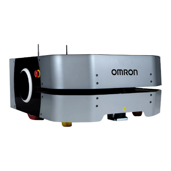
- Page 1 LD-250 Platform User's Manual LD-250 I642-E-07...
- Page 2 Every precaution has been taken in the preparation of this manual. Nevertheless, OMRON assumes no responsibility for errors or omissions. Neither is any liability assumed for damages resulting from the use of the information contained in this publica- tion.
-
Page 3: Intended Audience
Thank you for purchasing the LD-250 Autonomous Mobile Robot (referred to as AMR in this docu- ment). This manual is OMRON's original instructions describing the setup, operations, and user maintenance of the product. This document describes AMR functionality supported with FLOW v3.3.1. -
Page 4: Manual Information
Manual Information Manual Information Page Structure The following page structure is used in this manual. 5 Installation Unpack This section provides details on how to unpack the Industrial Panel PC. 5-1-1 Unpack Procedure Check the package for damage. If there is any visible damage: •... -
Page 5: Additional Information
Manual Information Precautions for Safe Use Precautions on what to do and what not to do to ensure safe usage of the product. Precautions for Correct Use Precautions on what to do and what not to do to ensure proper operation and performance. Additional Information Additional information to read as required. - Page 6 Manual Information LD-250 Platform User's Manual (I642)
-
Page 7: Sections In This Manual
Sections in this Manual Sections in this Manual Overview Specifications Installation Operation Troubleshooting Maintenance Appendices LD-250 Platform User's Manual (I642) -
Page 8: Table Of Contents
CONTENTS CONTENTS Introduction ......................1 Intended Audience............................1 Applicable LD Models ............................1 Units.................................1 Manual Information....................2 Page Structure..............................2 Special Information ............................2 Sections in this Manual ................... 5 Terms and Conditions Agreement................ 12 Warranty and Limitations of Liability ......................12 Application Considerations ..........................12 Disclaimers ..............................13 Safety Precautions.................... - Page 9 CONTENTS 1-2-14 AMR Core ..........................1-13 1-2-15 Speakers ...........................1-13 1-2-16 Docking Station .........................1-14 1-2-17 Localization Sensors .........................1-15 Autonomous Navigation .....................1-16 Labels............................1-18 1-4-1 AMR Information Label ......................1-18 1-4-2 Docking Station Information Label ....................1-18 Model Numbers ........................1-20 Optional Items ........................1-21 1-6-1 Fleet Manager ...........................1-21 1-6-2 Additional E-STOP Buttons .......................1-22 1-6-3...
- Page 10 CONTENTS 2-4-8 Operator Panel Screen ......................2-11 2-4-9 Wireless Specifications ......................2-11 2-4-10 DIGITAL IO Connector ......................2-12 2-4-11 AUX SENSORS Connector.......................2-13 2-4-12 RS232 Connector........................2-13 2-4-13 LIGHTS Connector........................2-13 2-4-14 USER INTERFACE Connector ....................2-14 2-4-15 USER BUMP Connector ......................2-14 2-4-16 AUX PWR Connector ........................2-15 2-4-17 USER PWR Connector ......................2-15 2-4-18...
- Page 11 CONTENTS 3-14 Commissioning ........................3-87 3-14-1 Commissioning Procedure ......................3-87 3-15 Map Creation Overview .......................3-88 3-15-1 Basic Mapping Tasks ........................3-89 Section 4 Operation Payload Movement and Transfer..................4-3 AMR Start-up ..........................4-4 AMR Shut-down ........................4-5 AMR Core LED Indicators .....................4-6 Workspace..........................4-7 4-5-1 Physical Barriers .........................4-8 4-5-2 Logical Barriers ...........................4-9 4-5-3...
- Page 12 CONTENTS 4-15-9 Driving Slowly, Scanning Laser E-STOP Inactive ..............4-37 4-15-10 Obstacle Detected / Protective Stop ..................4-37 4-15-11 Charging............................4-37 4-15-12 Booting ............................4-38 4-16 Manual Driving ........................4-39 4-16-1 Driving with the Pendant ......................4-39 4-17 Warning Buzzer ........................4-41 4-18 Back up and Restore the AMR....................4-42 4-18-1 Creating Backup Files .......................4-42 4-18-2...
- Page 13 CONTENTS 6-7-1 Cleaning Intervals ........................6-15 6-7-2 Cleaning AMR Charging Contacts ....................6-15 6-7-3 Cleaning Docking Station Charging Contacts ................6-16 6-7-4 Cleaning Laser Lenses ......................6-17 6-7-5 Cleaning Rear Sensor .......................6-17 6-7-6 Cleaning Caster Treads ......................6-18 6-7-7 Cleaning ESD Caster Treads ....................6-18 6-7-8 Cleaning Drive Wheels......................6-19 Distance Traveled by the AMR....................6-20 Replacing Items ........................6-21...
-
Page 14: Terms And Conditions Agreement
Omron’s exclusive warranty is that the Products will be free from defects in materials and workman- ship for a period of twelve months from the date of sale by Omron (or such other period expressed in writing by Omron). Omron disclaims all other warranties, expressed or implied. -
Page 15: Disclaimers
• Omron Companies shall not be responsible for the user’s programming of a programmable Product, or any consequence thereof. • Omron Companies shall not be responsible for the operation of the user accessible operating sys- tem (e.g. Windows, Linux), or any consequence thereof. -
Page 16: Safety Precautions
Safety Precautions Safety Precautions Definition of Precautionary Information The following notation is used in this manual to provide precautions required to ensure safe usage of the LD-series AMR. The safety precautions that are provided are extremely important to safety. Always read and heed the information provided in all safety precautions. The following notation is used. -
Page 17: Dangers
An appropriate number of persons is required to manually lift an AMR. OMRON recommends using a mechanical lift when possible. To avoid muscle strain or back injury, lifting with proper lifting technique is required. - Page 18 Safety Precautions Use only the specified tools, equipment, lubricants, and OMRON-supplied spare parts to service and maintain the AMR according to the specified service interval. Failure to do so could result in an unsafe operating state than might result in personal injury or damage to property.
-
Page 19: Battery And Docking Station
Safety Precautions The time-of-flight sensors will not prevent AMR rotation when an object is detected. OMRON is not responsible for any risks incurred by modifying safety zone sizes or other OS32C laser settings. The AMR as a partly-completed machine is intended to be incorporated into other machi-... -
Page 20: Operating Environment
If a payload is beyond the footprint of the AMR it can compromise its safety function. Payloads beyond AMR footprint may require modifying safety zone size. The OMRON AMR Safety Zone Generator tool is available for safety zone resizing. - Page 21 Safety Precautions A physical barrier must be easily detectable by the AMR and also strong enough to stop a fully-loaded AMR traveling at its maximum speed. Exposure to ingress beyond the specifications can lead to system malfunction. LD-250 Platform User's Manual (I642)
-
Page 22: Cautions
Safety Precautions Cybersecurity To maintain the security and reliability of the system, a robust cybersecurity defense pro- gram should be implemented, which may include some or all of the following: Anti-virus protection • Install the latest commercial-quality anti-virus software on the computer connected to the control system and keep the software and virus definitions up-to-date. - Page 23 Safety Precautions Follow all appropriate local safety regulations for working with isopropyl alcohol, includ- ing fire safety, toxicity, and protective clothing and gear requirements. Do not place any objects between the Docking Station and the AMR. Removing side skins exposes the AMR drive wheel motors, which can become extreme- ly hot during operation.
-
Page 24: Precautions For Safe Use
• In case of fire, use a type ABC or type BC dry chemical fire extinguisher. • Although the lasers used are Class 1/1M (eye-safe), OMRON recommends that you not look into the laser light. The maximum permissible exposure cannot be exceeded when viewing lasers with the naked eye. - Page 25 • If you suspect that liquid has penetrated the skins or contaminated the AMR's interior, do not at- tempt to power ON the system and contact your OMRON representative. • Do not allow any foreign metal objects to be near the AMR or Docking Station charging contacts.
-
Page 26: Precautions For Correct Use
If you find that you must frequently move the AMR, use MobilePlanner to reconfigure its route to avoid problematic areas. • OMRON recommends that you train personnel on the safe use of the brake release operations and procedures for safely pushing an AMR. - Page 27 Precautions for Correct Use • Only qualified personnel who have read and understood this manual should manually move or oper- ate the AMR. • The frequency of cleaning intervals depends on your particular system, its operating environment, and the amount of use. Cleaning intervals may need to be shortened for certain environments. •...
-
Page 28: Regulations And Standards
Regulations and Standards Regulations and Standards Conformance to EU Directives The AMR complies with the following EU Directives. Directives • 2006/42/EC Machinery Directive • 2014/30/EU EMC Directive EN / IEC Standards The AMR system conforms to the following EN standards. •... -
Page 29: Related Manuals
Related Manuals Related Manuals Use the following related manuals for reference. Manual Title Description Mobile Robot Software Suite User's Guide (Cat. No. Covers the basic procedures for installing and using I614) the Mobile Robot Software Suite EM1100 Enterprise Manager User Guide (Cat. No. Describes the installation and operation of an EM1100 I615) appliance, which runs the Fleet Operations Workspace... -
Page 30: Glossary
Debug Info File A zip file downloaded from SetNetGo that contains detailed information about the status of the system used by OMRON engineers for trouble- shooting. Docking Station A fixed object that the AMR engages with for autonomous charging. - Page 31 Glossary Term / Abbreviation Description Fleet Manager The operational mode of the computing appliance that runs the FLOW Core software to control a Fleet of AMRs. Fleet Operations Workspace A computing system that consists of software and hardware packages and (FLOW) is used to set up, integrate, and manage a Fleet of AMRs within a factory environment.
- Page 32 Glossary Term / Abbreviation Description A Printed Circuit Assembly (PCA) is a circuit board that is populated with electronic components. Pendant A handheld, external input device for manually driving AMRs that is typical- ly used for map creation. This may also be referred to as a Joystick in some cases.
-
Page 33: Revision History
Revision History Revision History A manual revision code appears as a suffix to the catalog number on the front and back covers of the manual. I642-E-07 Cat. No. Revision code Revision code Date Revised content July 2024 Reformat, corrections, and updates. September 2021 Minor corrections and updates. - Page 34 Revision History LD-250 Platform User's Manual (I642)
-
Page 35: Overview
Overview This section provides general information about the AMR. Intended Use....................1-3 Features and Components ................1-5 1-2-1 Lasers......................1-6 1-2-2 Skins........................ 1-7 1-2-3 Payload Bay ....................1-8 1-2-4 Operator Panel ....................1-8 1-2-5 E-STOP Buttons ....................1-9 1-2-6 Wireless Antennas ..................1-9 1-2-7 Light Discs ...................... - Page 36 1 Overview FLOW Core Software ................... 1-26 1-7-1 MobilePlanner Software ................1-26 1-7-2 Fleet Management Software ................. 1-28 1-7-3 SetNetGo Software ..................1-28 1-7-4 Driving and Navigation Software ..............1-29 1-7-5 Fleet Simulator Software ................1-30 Payload Considerations ................1-31 1-8-1 Payload Structures ..................
-
Page 37: Intended Use
OMRON does not provide the method of loading the payload on or off the AMR. It is the end user's responsibility to perform a complete task-based risk assessment in accordance with EN ISO 12100, and ensure safe transfer of the payload. - Page 38 1 Overview WARNING The AMR as a partly-completed machine is intended to be incorporated into other ma- chinery and must not be put into service until the final machinery into which it is to be incorporated has been declared in conformity with the provisions of EC Machinery Di- rective2006/42/EC, where appropriate.
-
Page 39: Features And Components
1 Overview Features and Components This section provides an overview of the basic features and components of the AMR. Item Description Item Description Low Laser Light Disc Removable Skin, refer to1-2-2 Skins on Access Panel page 1-7 for more information Safety Laser Scanner Rear Sensors Payload Bay (Top Plate shown) -
Page 40: Lasers
Precautions for Safe Use • Although the lasers used are Class 1/1M (eye-safe), OMRON recommends that you not look into the laser light. The maximum permissible exposure cannot be exceeded when viewing lasers with the naked eye. -
Page 41: Skins
1 Overview Low Laser One Low Laser detects obstacles below the scanning plane of the Safety Laser Scanner, such as an empty pallet or fork truck blades, which are too low for the Safety Laser Scanner's detection plane. The Low Laser is positioned near the floor and can detect objects that are at least 65 mm tall. The Low Laser also detects obstacles that might be significantly wider near the floor, such as a col- umn base, while the Safety Laser Scanner might detect only the upper, narrow portion of the column. -
Page 42: Payload Bay
1 Overview 1-2-3 Payload Bay The area between the AMR and the payload structure is the payload bay. This is where the AMR Core's power and I/O connectors are located, in addition to any mechanical fasteners that secure the payload to the AMR. Payload Support Structure The top plate in the payload bay contains longitudinal and transverse load-bearing extrusions that pro- vide adaptable mount points. -
Page 43: Key Switch
1 Overview ON and OFF Buttons ON and OFF buttons are used to start-up and shut-down the AMR under normal operating conditions. Integrated LED ring lights are provided around the buttons for visual indication of the AMR operating states. Emergency Stop Button The emergency stop button is connected to the safety circuit and has the same function as all other emergency stop buttons on the AMR. -
Page 44: Access Panel
1 Overview 1-2-8 Access Panel The Access Panel is located on the left rear skin of the AMR. Refer to the figure below for more infor- mation. The Access Panel is held in place with a push-push latch. This is where the Pendant Port and Maintenance Ethernet Port are located. -
Page 45: Rear Sensor
1 Overview Pendant Port The pendant port is used to connect a handheld pendant to the AMR. This is typically used when driv- ing the AMR manually. Disconnect the pendant from the pendant port during normal operation. 1-2-9 Rear Sensor The AMR includes a rear-facing sensor that detects obstacles that are close to the rear, such as a per- son stepping behind the AMR. -
Page 46: Pendant
1 Overview 1-2-12 Pendant Connect a Pendant to manually drive the AMR. A pendant is typically used when generating a map of the workspace. The pendant has a trigger switch that enables the directional control joystick while an operator is present and holding the switch. -
Page 47: Drive Train And Suspension
1 Overview 1-2-13 Drive Train and Suspension The AMR utilizes a differential-type drive train with two drive-wheels. This drive train style makes the AMR highly maneuverable and allows it to rotate in place. The drive wheels have solid polyurethane treads for traction and durability. The drive wheels discharge accumulated electrical charge to ground. -
Page 48: Docking Station
1 Overview Precautions for Correct Use When speakers are used as a means of notifying personnel of an approaching AMR, you must routinely verify that they are still functioning normally. Verify that the speakers are audible, and the sound level is at the same level as needed during the operation. 1-2-16 Docking Station The Docking Station enables the AMR to charge autonomously. -
Page 49: Localization Sensors
1 Overview 1-2-17 Localization Sensors Localization is the process by which the AMR determines its location within its work environment. The AMR's primary method of localization utilizes the Safety Laser Scanner to scan and detect features in its environment. Each drive wheel is equipped with an encoder that sends information to the navigation system about distance traveled and direction. -
Page 50: Autonomous Navigation
1 Overview Autonomous Navigation The AMR combines hardware and mobile-robotics software to provide an adaptive, mobile platform to transport a payload. It is equipped with a Natural Feature Navigation system which enables the AMR to navigate and perform its basic functions independently and without the need for facility modification. After it scans physical features in its environment, the AMR navigates safely and autonomously to any accessible destination. - Page 51 1 Overview Before an AMR enters a high-traffic area, you must take appropriate precautions to alert people work- ing in those areas. The AMR provides programmable warning features such as a warning buzzer, speech synthesis, and warning indicator lights. The AMR Core provides connectors that enable you to add additional warning indicators to your payload structure.
-
Page 52: Labels
1-4-1 AMR Information Label The AMR information label is described below. The following example may differ slightly from your pro- duct's label. Omron Robo cs and Safety Technologies, Inc. 4225 Hacienda Drive, Pleasanton, CA 94588 LD Series 37222- Model:... - Page 53 1 Overview Om ro n R o bo tics an d S afety Techn o lo gies , In c. 4225 Hacienda Drive , Pleasanton , CA 94588 LD Series Dock 12477 - 000 Rev : Model : P/ N :...
-
Page 54: Model Numbers
1 Overview Model Numbers AMR model numbers applicable to this document are provided in the table below. Model Number Item 37222-00000 LD-250 AMR 37222-20000 LD-250 AMR with Electrostatic Discharge Protection 1-20 LD-250 Platform User's Manual (I642) -
Page 55: Optional Items
1 Overview Optional Items Information about optional items is provided in this section. 1-6-1 Fleet Manager To manage and administer multiple AMRs in the same workspace, you must use a Fleet Manager run- ning the Fleet Operations Workspace (FLOW) software. The Fleet Manager is a computing device with a processor capable of running the Fleet Operations Workspace Core suite. -
Page 56: Additional E-Stop Buttons
1 Overview • Path planning information for the individual AMR's intended route. Additional Information • The AMR requires wireless communications when operating within a fleet. Refer to 3-4-3 Wireless Connection on page 3-14 for more information. • Details for the use and configuration of the functions are covered in the Fleet Operations Workspace Core User's Manual (Cat. -
Page 57: Side Lasers
Refer to 3-5-1 Payload Bay Connections on page 3-18 for more information. Additional Information You can optionally supply a signal tower which includes a built-in warning buzzer, or a dedicat- ed warning buzzer. Contact your OMRON representative for more information on the available options. 1-6-5... -
Page 58: Cell Alignment Positioning System
This feature also enables smoother and quicker loading and unloading of material, contributing to a shorter cycle time. The CAPS license part number is 20271-805. Contact your local OMRON representative for more in- formation. Additional Information Refer to the Fleet Operations Workspace Core User's Manual (Cat. -
Page 59: Digital I/O Terminal Block Kit
1 Overview 1-6-12 Digital I/O Terminal Block Kit The Digital I/O Terminal Block Kit provides a convenient method for connecting user-supplied input and output devices to the Digital IO connector on the AMR Core. The kit (part number 14165-000) includes a numbered terminal block, 0.76 m cable, and a mounting bracket. Additional Information The mounting bracket has four 5.5 mm diameter holes on a 50 mm x 75 mm pattern for fasten- ing purposes. -
Page 60: Flow Core Software
1 Overview FLOW Core Software The FLOW (Fleet Operations Workspace) Core software package consists of different software com- ponents that provide specific functionality during AMR configuration and operation. The information in this section provides an overview of the different FLOW Core software components, their functions, and interactions within the AMR system. -
Page 61: System Requirements
1 Overview CAUTION The AMR can have unexpected motion if it is controlled by multiple instances of Mobi- lePlanner. This software provides the following general functionality: • Map creation and editing with Forbidden Areas, charging locations, Goals, and other workspace fea- tures. -
Page 62: Fleet Management Software
Fleet Management Software Fleet Management software runs on the Fleet Manager hardware. It provides the following general functionality for a fleet of OMRON AMRs. • Intelligent Job assignment Reduces wasted time and movement by continuously looking ahead to anticipate which AMRs will be best positioned for upcoming Tasks. -
Page 63: Driving And Navigation Software
1 Overview Integration Toolkit (ITK) Package The Integration Toolkit is OMRON’s interface application that enables integration between the Fleet Manager and the end user’s client application, manufacturing execution system (MES), or warehouse management system (WMS). This integration layer facilitates autonomous control for a fleet of AMRs using standard communication methods including REST and SQL. -
Page 64: Fleet Simulator Software
Fleet Simulator Software Fleet Simulator software runs on the Fleet Manager hardware. It provides the following general func- tionality for a simulated Fleet of OMRON AMRs. • Assess impact of map changes, scaling, route changes, and new software features. • Simulate up to 10 AMRs in up to three separate Fleets. -
Page 65: Payload Considerations
1 Overview Payload Considerations This section describes considerations and requirements for AMR payloads. A payload is considered as any item(s) that are placed on the AMR for the purposes of securing, transporting, and transferring some object. A payload structure is typically required to secure an object during transport. -
Page 66: Payload Structures
1 Overview Precautions for Safe Use It is the end user's responsibility to make sure that the speed is appropriate for the payload that the AMR carries, and that the AMR movement does not cause payload instability or loss of AMR control. -
Page 67: Exceeding The Amr Footprint
Payloads beyond AMR footprint may require modifying safety zone size. The OMRON AMR Safety Zone Generator tool is available for safety zone resizing. • OMRON is not responsible for any risks incurred by modifying safety zone sizes or other OS32C laser settings. -
Page 68: Safety Laser Scanner Zone Obstruction
Some applications such as cart transportation may require modifying Safety Laser Scanner zones if a payload structure obstructs them. The OMRON AMR Safety Zone Generator tool is available for Safe- ty Laser Scanner zone modification. Any change to Safety Laser Scanner zones may require validation using operational testing in accordance to your applicable standards. -
Page 69: Coordinate System
1 Overview Coordinate System AMRs use the X, Y, Z, and Theta coordinate system displayed in the figure below. This information is relevant for some of the procedures used in this manual, such as identifying which are the left or right sides of the AMR. - Page 70 1 Overview 1-36 LD-250 Platform User's Manual (I642)
-
Page 71: Specifications
Specifications This section provides specifications for the AMR and other associated items. Performance Specifications ................2-2 Physical Specifications ................. 2-3 2-2-1 Dimensions...................... 2-3 2-2-2 Center of Rotation ................... 2-5 2-2-3 Center of Gravity ..................... 2-5 2-2-4 Payload Center of Gravity ................2-6 2-2-5 Weights ...................... -
Page 72: Performance Specifications
2 Specifications Performance Specifications Performance specifications for the AMR are provided below. Item Specification Maximum payload capacity 250 kg Run-time With full payload: approximately 8-10 hours With no payload: approximately 13 hours Swing radius 525 mm Turn radius 0 mm Maximum translational speed 1200 mm/s Maximum translational acceleration... -
Page 73: Physical Specifications
2 Specifications Physical Specifications Physical specification of the AMR and other items are provided below. 2-2-1 Dimensions Dimensional specifications are provided in the following sections. AMR Dimensions Physical dimensions of the AMR are provided below. Battery Dimensions Physical dimensions of the battery are provided below. 145.97 329.19 242.51... - Page 74 2 Specifications Wall Mount Free Standing and Floor Mount 146° 146° 3x Ø6 Wall Mount Bracket 8x 25 18x Ø6 98 ±20 Operator Panel Dimensions Physical dimensions of the Operator Panel are provided below. 175.9 11.41 88.9 24.99 19.19 81.73 40.86 13.75 30.96...
-
Page 75: Center Of Rotation
2 Specifications 79.6 80 60 2-2-2 Center of Rotation The dimensions of the AMR center of rotation is provided below. Side View Front View = Center of Rotation 2-2-3 Center of Gravity The dimensions of the AMR center of gravity are provided below. Side View Front View = Center of Gravity... -
Page 76: Payload Center Of Gravity
2 Specifications 2-2-4 Payload Center of Gravity The following figures show the calculated safe center of gravity placements for the AMR's maximum allowed payload weight. The payload's center of gravity must be within the area shown. These calculations assume the following conditions. •... -
Page 77: Environmental Specifications
2 Specifications Environmental Specifications Environmental specifications are provided in the following sections. 2-3-1 AMR Environmental Specifications Environmental specifications for the AMR are provided below. WARNING • Do not expose the AMR to rain or moisture. • Do not use the AMR in hazardous environments (explosive gas, and oil mist). WARNING Exposure to ingress beyond the specifications can lead to system malfunction. -
Page 78: Docking Station Environmental Specifications
2 Specifications AMR maximum speed is recommended for traversing gaps, and routine driving over gaps should be avoid- ed. Lower speeds may not traverse the gap. Faster or frequent driving over gaps will shorten the lifespan of the drivetrain components. 2-3-2 Docking Station Environmental Specifications Environmental specifications for the Docking Station are provided below. -
Page 79: Other Specifications
Weight 19 kg Values correspond to the latest LD-series AMR battery (20452-700). Contact your local OMRON representa- tive for older version battery specifications. Approximately 80% of nominal battery capacity will be available after using the battery at 100% depth of dis- charge at temperatures between 15°C to 35°C. -
Page 80: Acuity Specifications
2 Specifications 2-4-4 Acuity Specifications Specifications for the Acuity camera are provided below. Feature Specification Field of View 140° Power Input 12 VDC (±10%) supplied from platform, through power connector Power Consumption 3.3 W maximum 2-4-5 Docking Station Specifications Specifications for the Docking Station are provided below. Description Specification Maximum input current... -
Page 81: Drive Train
2 Specifications Additional Safety Safety Reset Safety Function Category PFHd Function Information Stop Type Type Safety Laser Scanner 4-13 Protective Stops Protective Auto- 3.9 x 10 detection on page 4-33 Stop matic Reset Forward overspeed 4-14 Overspeed Pro- Emergency Manual 3.9 x 10 tection on page 4-34 Stop... -
Page 82: Digital Io Connector
2 Specifications Item Description Signal Strength The minimum required signal strength is -60 dBm. Channel Interference No more than two detectable access points at a level of -85 dBm at any given location. No more than one access point at a signal strength higher than -85 dBm at any given location. -
Page 83: Aux Sensors Connector
2 Specifications Item Value Type NPN / Sinking 22 to 30 VDC Power supply voltage range Operational current range Iout ≤ 500 mA (per signal bank) ON state resistance (Iout = 0.5 A) Ron ≤ 0.14 Ω @ 85°C Output leakage current Iout ≤... -
Page 84: User Interface Connector
2 Specifications Item Specification Output voltage 22 to 30 VDC Recommended user-supplied Molex components are provided. Other compatible options are available. Re- fer to Molex for more information. Shared with digital output common 4 (pin 37). Voltage level depends on battery state of charge. 2-4-14 USER INTERFACE Connector Electrical and other specifications for the USER INTERFACE connector are provided below. -
Page 85: Aux Pwr Connector
2 Specifications Item Specification Maximum output current 10 mA Recommended user-supplied Molex components are provided. Other compatible options are available. Re- fer to Molex for more information. 2-4-16 AUX PWR Connector Electrical and other specifications for the User Interface connector are provided below. Additional Information Refer to AUX PWR on page 3-29 for connector signal information. -
Page 86: Joystick Connector
2 Specifications Pin Number Specification 1 to 6 Ground 7, 8 Voltage range: 22 to 30 VDC 4 A max. per pin (inductive / resistive) 9, 10 Voltage range: 22 to 30 VDC 11, 12 5 A max. per pin (inductive / resistive) Voltage level depends on battery state of charge. - Page 87 2 Specifications Additional Information Refer to AUDIO IN/OUT on page 3-32 for connector signal information. 2-17 LD-250 Platform User's Manual (I642)
- Page 88 2 Specifications 2-18 LD-250 Platform User's Manual (I642)
- Page 89 Installation This section describes how to install and configure the AMR for operation. Installation Introduction ................3-3 Docking Station Installation ................3-4 3-2-1 Mechanical Considerations ................3-4 3-2-2 Electrical Considerations................. 3-5 3-2-3 Attaching the Temporary Floor Plate ............... 3-5 3-2-4 Attaching to a Floor ..................
- Page 90 3 Installation 3-11-5 Other Acuity Adjustments................3-83 3-12 Wireless Antenna Relocation Procedure ........... 3-85 3-13 Attaching Warning Labels ................3-86 3-14 Commissioning .................... 3-87 3-14-1 Commissioning Procedure ................3-87 3-15 Map Creation Overview ................3-88 3-15-1 Basic Mapping Tasks..................3-89 LD-250 Platform User's Manual (I642)
-
Page 91: Installation Introduction
3 Installation Installation Introduction The general AMR installation steps are provided below. WARNING While conducting any work on the AMR, make sure it is located on a flat, level surface with casters chocked and emergency stop active to prevent unexpected movement. Install the Docking Station. -
Page 92: Docking Station Installation
3 Installation Docking Station Installation Make the following considerations before installing the Docking Station. WARNING Remove the AMR from a Docking Station when conducting any installation or mainte- nance actions. Precautions for Safe Use The Docking Station must be properly secured to the wall or floor prior to operation. •... -
Page 93: Electrical Considerations
3 Installation Size Description M5 x 4 Stainless steel shoulder bolts and washers (supplied with the dock- ing station. As required Appropriate screwdriver, hex socket, or driver bit for user-supplied fasteners. 3-2-2 Electrical Considerations When connecting the power cord from a wall outlet to its mating connector on the Docking Station, ensure that the power cord connector is seated completely and secured. -
Page 94: Attaching To A Floor
3 Installation Tip the Docking Station onto its back, so you can access the underside. Remove the two lowest screws (M4 x 12 flat-head), if present. Refer to the following figure for the locations of the screw holes. Screw Hole Screw Hole Screw Hole Additional Information... -
Page 95: Attaching To A Wall
3 Installation 3 x Ø6 3-2-5 Attaching to a Wall Use the following information to attach the Docking Station to the wall using the supplied mounting bracket. Refer to the following figure for dimensions and mounting hole locations. Units: mm Wall Mount Wall Mount Bracket 8x 25... -
Page 96: Charging Paddle Alignment Procedure
3 Installation Shoulder Bolt Holes Lower the Docking Station down, so the two bolts on the back of the Docking Station slide into the bracket to secure the Docking Station to the wall and complete this procedure. 3-2-6 Charging Paddle Alignment Procedure The Docking Station Charging Paddle vertical position must be checked and potentially adjusted for the correct height setting. - Page 97 3 Installation Slots Spring-loaded Lower Raise Bottom View of Docking Station The Charging Paddle roller height must be adjusted so that it engages with the AMR's docking funnel. If the height is too high, it will collide with the AMR docking funnel mechanism. If it is too low, the charging contacts will not mate and charging will not occur.
- Page 98 3 Installation Measure the distance from the floor to the top of the Charging Paddle roller. Set the position of the roller at a height slightly lower than the bottom surface of the docking funnel. Use the Charging Paddle adjustment mechanism to make adjustments if necessary. To adjust the height, pull the spring-loaded pin away from the slot, move to a new slot, and then release the pin to engage in a new slot.
-
Page 99: Battery Installation Procedure
During the initial AMR installation and configuration, install a fully-charged battery. Follow these steps to install a battery. WARNING Replace the battery only with an OMRON factory-supplied battery intended for use in the AMR. Precautions for Safe Use Two or more people are required to lift the battery. - Page 100 3 Installation Lift and slide the new battery into the AMR body. The connectors on the battery should be facing outwards towards the rear of the AMR while inserting. The battery weighs 19 kg. The battery has recesses at the front and the back for easier lifting. Attach the battery power and data cables to the connectors at the rear of the battery.
-
Page 101: Network Connections
3 Installation Network Connections Wireless and wired networks are available on the AMR. The wired network is typically used for initial configuration and troubleshooting. The wireless network is typically used during normal operation and can also be used for maintenance and troubleshooting. Use the information in this section to configure the network settings of the AMR. -
Page 102: Wireless Connection
3 Installation Right-click on the Ethernet N or LAN Connection. Click Properties, and then double-click the Internet Protocol Version 4 connection item to open its Properties window: Click the radio button next to Use the following IP address. Enter 1.2.3.X as the IP address and 255.255.255.0 as the Subnet mask. (Where x is any num- ber 1 through 255 excluding 4.) Click OK twice to exit both Properties dialogs, and then close the Network Connections screen. - Page 103 3 Installation • Use the SetNetGo tab in the MobilePlanner software. • Open a Web browser on your PC and enter the URL: https://10.10.10.10 to connect directly to the SetNetGo Web Interface on the AMR. Additional Information A workspace with a single AMR can operate without a wireless network. After accessing the SetNetGo interface, access the Management Interface area in the Network tab to enter the wireless connection network data.
-
Page 104: Wireless Considerations
3 Installation 3-4-4 Wireless Considerations It is recommended to use wireless network industry best practices. Always conduct a comprehensive workspace survey and test your wireless service before AMR configuration and operation begins. Make the following considerations when the AMR is communicating with a wireless network. Refer to 2-4-9 Wireless Specifications on page 2-11 for more information. -
Page 105: Port Forwarding
The AMR’s Core allows TCP and UDP port forwarding over the LAN 1 interface. This enables wireless access to onboard Ethernet devices, including OMRON Sysmac Machine Automation Controllers (MACs) and other Programmable Logic Controllers (PLCs). Through the controller, devices connected to the AMR’s DIGITAL I/O can be written to and read. -
Page 106: Electrical Connections
3 Installation Electrical Connections Use the following information to understand the AMR's electrical connections. 3-5-1 Payload Bay Connections Use the following information to make all necessary payload bay connections. Additional Information Refer to 2-4 Other Specifications on page 2-9 for more information on payload bay connector and electrical specifications. - Page 107 3 Installation DIGITAL IO The DIGITAL IO connector on the AMR Core provides digital inputs and outputs, typically used for payload control. Use the information below to understand all DIGITAL IO connections. The connector consists of 16 digital inputs and 16 digital outputs. The inputs are arranged in 4 banks of 4.
- Page 108 3 Installation The following diagram provides details about input wiring for banks of inputs. Bank 1 is shown with a Sinking (NPN) wiring scheme and Bank 2 is shown with a Sourcing (PNP) wiring scheme. Bank 1 Inputs Input 1.1 Input 1.2 Input 1.3 Input 1.4...
- Page 109 3 Installation Pin Number Designation Details Output 1 Output 2 Output 3 Output 4 Output 5 Output 6 Output 7 Output 8 Outputs Output 9 Output 10 Output 11 Output 12 Output 13 Output 14 Output 15 Output 16 500 mA max. *1, *2 Output Common 4 500 mA max.
- Page 110 3 Installation Ground Output 1 Load Output 2 Load Output 3 Load Output 4 Load Output 5 Load Output 6 Load Output 7 Load Output 8 Load Output 9 Load Output 10 Load Output 11 Load Output 12 Load Output 13 Load Output 14 Load...
- Page 111 3 Installation PIN 5 PIN 1 PIN 10 PIN 6 PIN 15 PIN 11 The information in the table below describes the signal designations for the AUX SENSORS connec- tor. Pin Number Designation Details TXD Side Laser 1 /dev/ttyUSB5 TXD Side Laser 2 /dev/ttyUSB6 TXD Low Laser /dev/ttyUSB7...
- Page 112 3 Installation PIN 1 PIN 5 PIN 6 PIN 9 Communication Pin Number Designation Channel RS232-1 RS232-2 Ground Legacy Core RS232 Connector Arrangement The following figure shows the RS232-1 and RS232-2 connector pin arrangements when the op- tional RS232 splitter cable is connected (part number 24010-000F). This optional cable provides two RS232 ports similar to legacy AMR Core connectors.
- Page 113 3 Installation LAN 1 The LAN 1 connector on the AMR Core is a general purpose, shielded, Auto-MDIX Ethernet port. It provides Ethernet connections for peripheral devices on a user LAN. LAN 2 The LAN 2 connector on the AMR Core is reserved for future use. LIGHTS The LIGHTS connector on the AMR Core provides outputs for user-supplied signaling devices such as signal beacons or buzzers.
-
Page 114: User Interface
3 Installation USER INTERFACE The USER INTERFACE connector on the AMR Core provides circuits for connecting various user-sup- plied control devices. A jumper must be present between pins 4, 11, and 5, 12 if user-supplied emer- gency stop devices are not used. Use the information provided below to understand the signals pro- vided by the USER INTERFACE connector. - Page 115 3 Installation Pin Number Item Description Safety circuit channel 1 out- Dual channel safety rated outputs to provide control of external systems. Channels are switched simultaneously within 100 ms put low side of each other; and checked for proper state. Safety circuit channel 2 out- put low side Off button input...
- Page 116 3 Installation AMR Core PIN 4 PIN 5 User-supplied Emergency Stop PIN 11 Devices PIN 12 PIN 1 PIN 2 PIN 3 User- User- User- 22 to 30 VDC supplied supplied supplied (Battery) Brake Button Button Button PIN 8 PIN 9 PIN 10 PIN 6 PIN 7...
- Page 117 3 Installation The USER BUMP connector on the AMR Core provides 6 circuits for optional user-supplied payload structure bumpers. These circuits are used to add front left, center, and right sensors, and rear right, center, and left sensors. When the Bumper output signal is connected to a Bumper input, the AMR will stop. A normally open contact should be used to activate individual bumper signals.
- Page 118 3 Installation PIN 6 PIN 4 PIN 1 PIN 3 The information in the table below describes the signal designations for the AUX PWR connector. Pin Number Designation 1, 2, 3 5 VDC 12 VDC 20 VDC USER PWR The USER PWR connector on the AMR Core provides unregulated battery power, usually used for payload structure devices.
-
Page 119: Hmi Panel
3 Installation Pin Number Description Software Control 1 to 6 Ground Battery output 1. Switchable in software: Bat- tery_Out_1 Battery output 2. Switchable in software: Bat- tery_Out_2 9, 10 Battery output 3 and 4. Switchable in software: Bat- tery_Out_3_and_4 11, 12 Battery output 5 and 6. -
Page 120: Audio In/Out
3 Installation OPT OUT The OPT OUT connector is an isolated audio connector, and can be used to output sound or expand the existing speaker system with less noise than the analog IN/OUT connectors. Additional Information Refer to 2-4-20 OPT OUT Connector on page 2-16 for connector information. The ANT connectors on the AMR Core provide threaded ports for WiFi antennas. -
Page 121: Attaching The Payload
3 Installation Attaching the Payload Use the information in this section to understand design considerations and other factors for attaching a payload to the AMR. 3-6-1 Payload Structure Mounting Points Several load-bearing bars are provided beneath the top cover for various payload structure designs. These mounting points allow you to adjust and position your payload in relationship to the AMR's cen- ter of gravity. - Page 122 3 Installation Location of the clip nuts Longitudinal T-nut extrusion Transverse T-nut extrusion 182.5 752.5 492.5 20.6 192.5 Extrusion Mounting Points Secondary Mount Points - Top Plate Clip Nuts Clip nuts (14) around the rim of the top plate can accept smaller loads such as payload skins or cov- ers.
- Page 123 3 Installation 25.0 867.5 0 67.3 267.5 467.5 667.5 910.0 662.5 580.0 392.5 292.5 105.0 20.0 Clip Nut Mounting Points 3-35 LD-250 Platform User's Manual (I642)
-
Page 124: Relocating The Operator Panel
3 Installation Relocating the Operator Panel Some applications may require relocating the Operator Panel if a payload structure obstructs it. The Operator Panel can be removed and relocated to a convenient location, typically on the payload struc- ture. If the Operator Panel is not needed, it can be removed. A jumper plug (part number 13387-000) is supplied with the AMR for use in this case. -
Page 125: Adding Additional Object Detection Sensors
3 Installation Adding Additional Object Detection Sensors The following sections provide details about side laser installation and other configuration require- ments. Adding additional side lasers is the most common solution for detecting objects that are not visible with the standard onboard sensors. Other sensor positions and orientations are also supported. 3-8-1 Installation Prior to mounting the laser, the following points should be considered:... -
Page 126: Configuration
3 Installation • 3 mm hex key Install the lasers as follows: At the mounting location, create holes spaced at the proper distance for the mounting plates on each side. Create holes for the laser guards to be installed. Ensure the position of the holes is such that the laser guards can be installed over the lasers without obstructing the sensing area. - Page 127 3 Installation 6) LaserFlipped: Enable the option for the left laser only. 7) LaserIsTilted: Enable the option if the lasers are being used for vertical object detection. 8) LaserTiltedNegativeSensor: Disable the option if LaserIsTilted is enabled. Save the configuration and wait for the AMR to reboot. Open the workspace map and verify the laser readings.
- Page 128 3 Installation 130 mm 410 mm 565 mm Ignored Segments By default, the sensor scans an arc of 270 degrees. Segments of this arc may intersect with parts of the AMR, its payload, or laser protective covers. Therefore, these segments must be configured as ig- nored in the software.
-
Page 129: Setting Values
3 Installation The procedure for identifying and inputting the ignored segments into MobilePlanner is as follows: 1. Begin at the 0° mark. Follow a counter-clockwise path along the positive range of the arc (between 0° and 180°) to identify the start and stop angles of segments to be ignored. 2. - Page 130 3 Installation Click to expand Robot Physical. Under Laser_3 and Laser_4, enter the lasers' mounting loca- tion coordinates for the following parameters: • LaserX • LaserY • LaserZ Use the LaserIgnore parameter to specify any ignored segments of the sensing field. Verify the laser configured as left is physically mounted on the left side of the AMR.
-
Page 131: Haps Installation And Configuration
The following sections also provide details about HAPS sensor installation and software configuration. If HAPS sensors are required but not present on the AMR, contact your local OMRON representative for more information about ordering them. The HAPS option is compatible with ARAM version 4.7.6 or later software. - Page 132 3 Installation Prepare the AMR so that it can be tipped it on its side. This might require removing the payload or the top cover skin, if installed. You must remove the E-Stop button from one side of the AMR to prevent damage to the button.
- Page 133 3 Installation It requires at least two people to complete this step. Use padding for the floor to prevent dam- age to the AMR before attempting this step. Tip the AMR on its side (A). Secure the AMR so that it cannot move. Find the speaker assembly (B) toward the front of the AMR as shown in the following figure.
- Page 134 3 Installation Feed the cable behind the speaker mount as shown in the following figure. Use a zip tie to se- cure the cable to the available cable tie mounts positioned on the chassis, leaving no slack. Pass the RS232 connector up through the oval hole in the side of the chassis as shown in the following figure.
- Page 135 3 Installation Pass the connector up through the oval slot in the payload bay, as shown in the following fig- ure. Payload Bay Oval Slot Connect the sensor's DB9 plug to the RS232-1 port. Refer to RS232 on page 3-23 for more information. Connect the Molex Mini-fit power plug to the USER PWR connector on the back side of the AMR Core.
- Page 136 3 Installation Prepare the AMR so that it can be tipped it on its side. This might require removing the payload or the top cover skin, if installed. You must remove the E-Stop button from one side of the AMR to prevent damage to the button.
- Page 137 3 Installation It requires at least two people to complete this step. Use padding for the floor to prevent dam- age to the AMR before attempting this step. Tip the AMR on its side (A). Secure the AMR so that it cannot move. Find the speaker assembly (B) toward the front of the AMR as shown in the following figure.
- Page 138 3 Installation Feed the cable behind the speaker mount as shown in the following figure. Use a zip tie to se- cure the cable to the available cable tie mounts positioned on the chassis, leaving no slack. Pass each RS232 connector (one at a time) through the oval hole in the side of the chassis as shown in the following figure.
- Page 139 3 Installation Pass the connectors up through the oval slot in the payload bay, as shown in the following fig- ure. Payload Bay Oval Slot Connect the front sensor's DB9 plug to the RS232-1 connector. Refer to RS232 on page 3-23 for more information. Install the power splitter cable into the USER PWR connector, as shown in the figure above, and connect the Molex Mini-fit plug power to the power splitter cable.
-
Page 140: Reassembly Procedure
3 Installation Route the cable as follows, fastening it to cable mounts with zip ties and leaving no slack in the cable. Callout Description of Cable Route Behind the drive assembly, close to the chassis. Over the caster mount. Behind the drive motor. Along the underside of the payload bay, close to the chassis (D). -
Page 141: Tape And Marker Application
Markers (short sections of the tape) are used to signal the AMR where to stop. Precautions for Correct Use • OMRON does not provide the protective coverings with the HAPS option. A protective cover- ing needs to be installed when applying the magnetic tape to the floor to prevent damage from the AMR traffic. -
Page 142: Software Configuration
3 Installation Conveyor 1 Conveyor 2 Main Track 20 to 30 30.0° 800 min. min. Front HAPS Sensor Goal 1 Goal 2 Rear HAPS Sensor If you use the same magnetic tape for markers as for the main tape strip, apply the markers upside- down, relative to the tape. -
Page 143: Goals And Tasks
3 Installation AMR Physical HAPS Configuration Adjust the following parameters in the Robot Physical section of MobilePlanner to configure the use of the HAPS sensor. GuideSensor_Front parameter settings: • Check the AutoConnect Check Box. • Set the Port parameter value to /dev/ttyUSB9. GuideSensor_Rear parameter settings: •... - Page 144 3 Installation Additional Information In this context, a Goal on the AMR’s map is used as a starting point for Tasks that will drive the AMR along the tape, stopping at markers along the tape. There will be no Goals on the tape itself.
- Page 145 3 Installation Determines how close Goals need to be for them to be considered as the same location. A toler- ance larger than the distance between the Goals will indicate that the Goals are at the same loca- tion. After entering True for this value, you will be given a choice of distance. The defaults are generally suitable.
-
Page 146: 3-10 Caps Configuration
3 Installation 3-10 CAPS Configuration The following sections provide details about CAPS software configuration. The CAPS license part number is 20271-805. Contact your local OMRON representative for more in- formation. 3-10-1 Normal Setup This section covers the configuration steps for a Normal CAPS setup. -
Page 147: Final Settings
3 Installation Target Shape This dropdown controls which target the AMR will locate and move relative to in the operating space. The Standard shape is the default. Refer to Fleet Operations Workspace Core User's Manual (Cat. No. I635) for more information on Standard targets. Other shapes can be used based on need and space requirements. -
Page 148: Parameter Mode
3 Installation Parameter Mode This parameter toggles the Normal and Advanced setting menus. Normal only shows the parameters previously described in this section. Refer to 3-10-2 Advanced Setup on page 3-60 for more informa- tion about the parameters in Advanced. 3-10-2 Advanced Setup This section covers the configuration steps for an Advanced CAPS setup. -
Page 149: Search Mode
3 Installation Timeout This sets the time before the AMR declares a timeout failure. The timer begins at the time the Task first starts looking for the reference target. If the Tasks has not reached the desired ending position before the specified time, the system will come to a stop, and signals failure of the Goal Task. Path Shape This parameter selects the desired path to the end position. -
Page 150: Fail Mode
3 Installation detrimental effects on the application. Using this mode will result in more failed Tasks, especially when operating large fleets as each scanning laser has its own intrinsic errors and noise profiles that affect the final match quality. Fail Mode This parameter controls the different failure modes that would cause the Task to immediately fail in- stead of attempting recovery to finish the Task within the FailTime timeout. - Page 151 3 Installation Front Clearance Side Clearances Back Clearance 100 mm 250 mm 20 mm • Custom: You can specify the area around the AMR for obstacle protection while moving to the final location. These parameters are only visible when Clearance Shape is set to Custom. Refer to the following figure.
- Page 152 3 Installation Drive Mode This parameter controls the driving behavior of the AMR. • Normal: A balanced optimization giving the best all-around driving behavior. • Precise: Minimizes Path and final error at the expense of being slower and with increased jitter in its motion.
- Page 153 3 Installation Additional Information • The OffsetCorrection parameters are only available to PrecisionDrive if there is a CAPS li- cense activated. • In typical applications, the AMR's overall approach and motion generally stay consistent and a single OffsetCorrection configuration is sufficient. Only one OffsetCorrection (X, Y, and Angle) is allowed for each AMR.
-
Page 154: 3-11 Acuity Installation Procedure
3 Installation 3-11 Acuity Installation Procedure Use the following information to install and configure an Acuity system. An optional Acuity Camera Kit is required for this procedure (part number 13700-000 with digital level, 13700-100 without digital level). Acuity software is included in the FLOW Core software suite. No additional software installation is re- quired for enabling Acuity localization. -
Page 155: Acuity Hardware Installation
3 Installation Direction of Travel Camera mounting hardware dimensions are provided below. 26.7 103.6 103.6 91.7 91.7 23.6 72.1 Label on Back 6x R1.5 Through Hole R5.1 R5.1 30.5 3x Ø 5.3 90° on Ø 31 Through Holes Equally Spaced Ø... - Page 156 3 Installation The figures in this section show the camera assembly being mounted to a bracket. This is only used to show where the screws will attach. A typical installation will have the mounting holes at the top of the AMR's payload structure.
- Page 157 3 Installation The screws have to be inserted from inside the payload structure, through the payload struc- ture surface and camera enclosure base, and into the three clinched nuts in the bottom of the camera bracket. Camera Mounting Bracket Camera Enclosure Base Test Bracket Shown for Illustration Only 3x M4 x 12 screws...
- Page 158 3 Installation 3x M3 x 4 Button Head Cap Screws Camera Mounting Bracket Camera Attach the camera tube assembly onto the camera enclosure base. 3-70 LD-250 Platform User's Manual (I642)
- Page 159 3 Installation The threads at the bottom of the tube are coarse, and match the threads on the base. The threads at the top of the tube are fine, and match the filter. Tube Base Install the foam dust seal and filter: •...
- Page 160 3 Installation Filter Foam Seal Tube Completed Assembly This completes the camera installation procedure. Camera Connections Procedure Use the following procedure to make the camera connections to the AMR. The camera hardware should be mounted to the AMR with cables connected to the camera before be- ginning this procedure.
-
Page 161: Configuration And Setup
3 Installation 3-11-3 Configuration and Setup The following sections provide details about Acuity setup and other configuration considerations. Enabling Acuity Enable Acuity localization functionality in the following areas: • MobilePlanner • SetNetGo • From the map The following sections will describe actions to enable Acuity in these areas. Additional Information Light Localization and Laser localization are designed to be used at the same time. - Page 162 3 Installation Importing the Camera Calibration Acuity cameras are supplied with a calibration file, which you will need to import before Acuity lo- calization can be used. The LightLocalization parameter must be enabled as described in Enabling Acuity In MobilePlanner on page 3-73 before attempting to import the file.
- Page 163 3 Installation Compensating for Camera Position and Tilt Procedure Use the following procedure to compensate for camera position and tilt. Enter the position of the camera with respect to the AMR into the MobilePlanner software. A dual-axis digital level (included in kit) is required for this procedure. X = 0 X = 0 Y = 0...
- Page 164 3 Installation of the camera is facing the rear of the AMR, the CameraOffsetTh will be 90, as a counter- clockwise rotation is positive. Finally, measure the tilt of the camera with respect to the floor using the dual-axis digital level that is included with the Acuity Camera kit.
-
Page 165: Mapping With Acuity
3 Installation It will only fit one way, with the slot in the plastic base of the level fitting over the back side of the camera mounting bracket. The slot is called out in the preceding figure. Enter the values directly from the display into MobilePlanner > Config X AXIS = Robot Physical >... -
Page 166: Scan Pattern
3 Installation Light Height Before scanning, measure the height from the floor to the lights. Use the height of the lights, not the ceiling, as most lights are set away from the ceiling by some amount. For diffused fluorescent lights, in an office setting, the ceiling height is typically fine. - Page 167 3 Installation The image below shows the map created based on the scan above. Lights are represented as light blue rectangles on the map created from this scan. Lights at Multiple Heights The scan contains the necessary data for all of the lights in the environment. When creating a map from the scan, specify a height range for the lights you want included in that map.
- Page 168 3 Installation If you are satisfied with the map: 1) Verify that the lights are where they should be, and their general dimensions are accurate. 2) Save the map to the PC. If there are lights at multiple heights, do not click Finish on the Scan Processing Tools tool- bar.
- Page 169 3 Installation Verify that the lights are where they should be, and their general dimensions are accurate. If you are satisfied with the appearance of the lights in this height range, save the new map with a different file name. Repeat these steps for as many different light heights as are needed.
- Page 170 3 Installation 3) Click Insert to complete the insertion. Zoom back out and use the Region Tool, from the Insert Map Tools toolbar, shown below, to click and drag a rectangular region that includes the lights you want inserted. Click the dropdown arrow next to the Insert button on the Insert Map Tools toolbar and click Advanced.
-
Page 171: Other Acuity Adjustments
3 Installation turned on. Click Insert on the Advanced Insert Dialog box and save your changes. Repeat the steps in this section for all other map areas with different light heights. If you are satisfied with the map: 1) Save it to your PC. If you have lights at multiple heights, do not click Finish on the Scan Processing Tools tool- bar. - Page 172 3 Installation Interpreting Light Objects on the Map Lights are represented by light blue rectangles. If lights do not appear on the map, enable their display by using the Map > Map Data > Light Items menu item in MobilePlanner. From Map >...
-
Page 173: Wireless Antenna Relocation Procedure
3 Installation 3-12 Wireless Antenna Relocation Proce- dure Use the following procedure to relocate the wireless antennas. This procedure details the relocation of one of the antennas and should be repeated if both antennas need to be relocated. Precautions for Correct Use It is the end user's responsibility to ensure that the payload does not attenuate the wireless an- tennas' signal. -
Page 174: 3-13 Attaching Warning Labels
3 Installation 3-13 Attaching Warning Labels A No Riding warning label is provided with the AMR. This must be placed in a prominent location on a flat, horizontal surface on the payload structure or AMR itself, where a person could sit or stand. The label should be placed where the operators will see it and must be visible from at least two opposing sides of the AMR. -
Page 175: 3-14 Commissioning
3 Installation 3-14 Commissioning The commissioning procedure is executed within MobilePlanner. Refer to Fleet Operations Workspace Core User's Manual (Cat. No. I635) for more information. It is used to confirm the correct operation of the following equipment and functions: • Self Health system check •... -
Page 176: 3-15 Map Creation Overview
3 Installation 3-15 Map Creation Overview A map is a scanned representation of the floor plan in the AMR's operating space. Maps contain the static features in the AMR's environment, such as walls, doors, permanent shelving, etc. They also contain user-definable sectors, lines, and areas that help the AMR perform its Job. Maps also contain a variety of Goals, Routes, and Tasks that comprise the destinations and activities of the AMR in the workspace. -
Page 177: Basic Mapping Tasks
3 Installation Regardless of the constraint specified by any virtual element on the map, the AMR always operates according to its safety protocols. For example, when the AMR is following a preferred line it will still respond to and avoid dynamic obstacles. Additional Information Refer to Fleet Operations Workspace Core User's Manual (Cat. - Page 178 3 Installation 3-90 LD-250 Platform User's Manual (I642)
-
Page 179: Operation
Operation This section provides information about the operation of the AMR. Payload Movement and Transfer ..............4-3 AMR Start-up ....................4-4 AMR Shut-down....................4-5 AMR Core LED Indicators................4-6 Workspace ...................... 4-7 4-5-1 Physical Barriers ..................... 4-8 4-5-2 Logical Barriers ....................4-9 4-5-3 Obstacles ...................... - Page 180 4 Operation 4-12 Emergency Stop ................... 4-31 4-12-1 Emergency Stop Recovery Procedure ............4-31 4-13 Protective Stops ................... 4-33 4-14 Overspeed Protection .................. 4-34 4-15 Light Discs and Optional Beacon States ........... 4-35 4-15-1 Driving Straight....................4-35 4-15-2 Turn Signal ....................4-35 4-15-3 Emergency Stop....................
-
Page 181: Payload Movement And Transfer
4 Operation Payload Movement and Transfer A typical AMR application uses a payload structure to transport objects within a facility. For example, the AMR might pick up and carry a crate of parts from one conveyor belt then deliver it to another con- veyor belt. -
Page 182: Amr Start-Up
If you suspect that liquid has penetrated the skins or contaminated the AMR's interior, do not attempt to power ON the system and contact your local OMRON representative. During normal start-up, the AMR powers all of its systems, including all factory and user configura- tions. -
Page 183: Amr Shut-Down
4 Operation AMR Shut-down Pressing the OFF button will shut down the AMR in a controlled manner. The system will save the AMR's last known location so it can automatically localize when it is powered ON later. When the AMR is shut down using the OFF button, it enters a standby state. In this state, some sys- tems remain active and consume low power. -
Page 184: Amr Core Led Indicators
4 Operation AMR Core LED Indicators The AMR Core has 12 indicator LEDs that give a visual overview about its status. The following figure displays the AMR Core LED indicator lights. The following table describes the AMR Core LED indicator activity. LED Indicator Description LOGIC... -
Page 185: Workspace
4 Operation Workspace The workspace is considered to be any area where the AMR will travel. It must be carefully evaluated and prepared before the AMR is placed into operation. Use the information below to adapt your work- space for optimal AMR performance. The workspace must be flat, free of clutter and debris, and have adequately wide doorways and corri- dors to allow navigation by an AMR. -
Page 186: Physical Barriers
4 Operation Make the following considerations when traversing steps or gaps. • Observe the maximum step and gap traversal details provided in 2-3-1 AMR Environmental Specifi- cations on page 2-7 • Frequent driving over steps or gaps will shorten the lifespan of the drivetrain components. •... -
Page 187: Logical Barriers
4 Operation • The minimum detectable size of a barrier is 300 mm x 300 mm and must be mounted no higher than 100 mm from the floor. 4-5-2 Logical Barriers In addition to physical barriers, use MobilePlanner to create Forbidden Areas or Lines as logical barri- ers on the workspace map to prevent AMRs from closely approaching a fall hazard. -
Page 188: Operating Hazard Zones
4 Operation Only authorized persons are permitted to enter restricted zones. You may need to implement map features such as Forbidden Areas to keep AMRs within their desig- nated area of operation. Refer to the Fleet Operations Workspace Core User's Manual (Cat. No. I635) for information about adding restricted zones to your workspace map. -
Page 189: Clearances
4 Operation Clearances The AMR must operate in an environment that is generally flat, with no doors or other restricted areas that are too narrow for the AMR to pass through. The AMR is designed to operate in environments that contain doors, passageways, or other constrained areas that are wide enough for it to traverse. You must ensure that adequate clearance is maintained on each side of the AMR, so that a person cannot get trapped between the AMR and a wall or other fixed object. -
Page 190: Docking Clearances
4 Operation Front Additional Information The AMR's Light Discs display a distinct turn signal pattern when it rotates. Refer to 4-15 Light Discs and Optional Beacon States on page 4-35 for more information. 4-6-2 Docking Clearances Set a 1500 mm distance between the Docking Station Goal (defined in the map) and the dock Goal position of the AMR using MobilePlanner. -
Page 191: Narrow Passageway Behavior (Linear)
4 Operation considered hazard zones. You must make these areas visually distinct. Personnel that will work near these zones must be trained and informed about your chosen method used to make docking area haz- ard zones visually distinct. An example of this is shown below, utilizing floor markings to draw attention to the docking area hazard zones. - Page 192 4 Operation 1700 8000 1300 1300 Start Goal End Goal 1350 4-14 LD-250 Platform User's Manual (I642)
-
Page 193: Immobilization
4 Operation Immobilization In rare circumstances, it is possible for the AMR to become physically immobilized in a position from which it cannot move without operator assistance. Immobilization may also occur from a low battery or AMR error. WARNING Immobilization might cause motors in the AMR to overheat, resulting in a fire. Additional Information Side Lasers increase detection of overhanging objects and floor obstacles. -
Page 194: Battery And Charging
4 Operation Battery and Charging The AMR battery supplies adequate power for the motors, electronics, and accessories. Typical runtime with no load is approximately 13 hours. Typical fully-loaded runtime is approximately 8-10 hours. The primary factors that affect runtime are AMR speed, acceleration, idle time at Goal lo- cations, payload amount, and power consumed by accessories. - Page 195 AMR. Additional Information The details provided in this section apply to current LD batteries with a part number 20452-700. Previous generation batteries operate differently. Contact you local OMRON representative for more information. 4-17...
-
Page 196: Battery Removal And Installation
4 Operation 4-8-2 Battery Removal and Installation Removal or installation of the battery must be performed by persons who have read and understood this manual. WARNING • Do not damage the battery by subjecting it to impacts or shocks. Using a damaged battery can result in fire or other dangerous conditions. - Page 197 4 Operation Battery Removal Procedure Use the following procedure to remove the battery from the AMR: Shut down the AMR. Remove the battery door skin to access the battery compartment. Refer to 3-3 Battery Installa- tion Procedure on page 3-11 for more information. Unlatch and open the battery door by sliding the latch (A) to the right (B), as shown in the fig- ure below.
-
Page 198: Docking Station
4 Operation Support the battery at the bottom (B) as you pull it in the direction of the arrow (C) to prevent it from falling. Pull the battery out and use the handles at the front and rear of the battery to carry it. After the battery is removed from the compartment, this procedure is complete. -
Page 199: Additional Information
4 Operation Precautions for Correct Use The Docking Station can only be connected directly to the AMR or to one battery. Simultaneous charging configurations are not possible. The Docking Station has a power switch and two indicator LEDs: • Blue indicates that power is available. •... - Page 200 4 Operation Autonomous Charging During normal operation, the AMR charges its battery autonomously by driving to the Docking Station under configurable conditions (battery level and opportunities). The AMR drives to the location of the Docking Station based on the map loaded onto the AMR and it uses this information to autonomously recharge as configured.
-
Page 201: Balancing The Battery
4 Operation The Docking Station provides a charging port on its left side. Charging a battery outside the AMR is accomplished by using the supplied manual charge cable with this port and connecting it directly to the battery. When the battery is connected to the Docking Station, a 10 second delay occurs during an automatic check sequence and then charging begins when the amber charging LED is ON solid. -
Page 202: Storing Batteries
4 Operation perform a periodic battery exchange with a completely charged and balanced battery at regular in- tervals, such as once a month. The interval between battery exchanges depends on the AMR‘s use and will vary with the weight it carries, the electrical load of any accessories, and percentage of time it is in service. -
Page 203: Operator Panel
4 Operation Operator Panel The information below describes the operator panel components and functions. 4-9-1 Main Screen Information displayed on the main screen during AMR operation is described below. WiFi Signal Strength Battery Level IP Address Robot ID Main panel Additional Information Refer to 5-6-1 Text Messages on page 5-11 for more information. -
Page 204: Emergency Stop Button
Precautions for Safe Use If you suspect that liquid has penetrated the skins or contaminated the AMR's interior, do not attempt to power ON the system and contact your local OMRON representative. Additional Information There is a 2.5 second delay between when the ON button is pressed and the AMR resumes its activity. -
Page 205: Brake Release Button
4 Operation Precautions for Correct Use • Avoid moving the AMR while it is powered OFF. If you manually move the AMR while it is powered OFF, it may not be able to determine its current location when it is powered ON again. -
Page 206: 4-10 Releasing The Brakes
AMR manually when it is positioned on an inclined surface, unless necessary pre- cautions have been taken to prevent uncontrolled rolling of the AMR. Precautions for Correct Use OMRON recommends that you train personnel on the safe use of the brake release operations and procedures for safely pushing an AMR. 4-28... -
Page 207: 4-11 Manually Pushing The Amr
• If the loaded AMR is too heavy to move manually, it is recommended that you seek additional help or remove the payload. • OMRON recommends that you train personnel on the safe use of the brake release opera- tions and procedures for safely pushing an AMR. - Page 208 4 Operation Use the following procedure to engage or disengage the drive wheels. 1. If the battery is installed, press an E-STOP button to disable power to the motors for safety during the procedure. 2. If the AMR is not on its shipping pallet, chock the casters to prevent the LD-250 from rolling. 3.
-
Page 209: 4-12 Emergency Stop
4 Operation 4-12 Emergency Stop When an emergency stop is triggered, the AMR decelerates to a controlled stop, de-energizes the safety outputs, and then disables its motors and engages the brakes. The emergency stop circuit is classified as a Category 1 stop according to IEC 60204-1 (NFPA79). Typical reasons to activate an emergency stop during normal operation are: •... - Page 210 4 Operation Press the ON button on the Operator Panel. MobilePlanner can also be used instead of pressing the ON button by clicking Enable in the E- STOP dialog box. Additional Information There is a 2.5 second delay between when the ON button is pressed and the AMR resumes its activity.
-
Page 211: 4-13 Protective Stops
4 Operation 4-13 Protective Stops When a protective stop is triggered, the AMR decelerates to a stop at the maximum allowed rate. It then removes power to its motors and engages the brakes. After the AMR comes to a complete stop, it waits a minimum of 2.5 seconds before it resumes operation. -
Page 212: 4-14 Overspeed Protection
If this fault occurs frequently, the operating conditions leading up to this event should be investigated. Contact your OMRON representative for support. If the problem is not resolved, the AMR may stop operating in order to prevent the use of the potentially degraded brakes. Generally, the degradation of the motor brakes requires hundreds of these occurrences. -
Page 213: Light Discs And Optional Beacon States
4 Operation 4-15 Light Discs and Optional Beacon States Light Discs located on the sides of the AMR provide a visual indication of its operational state. Use the following information to understand the operation of the Light Discs and any user-supplied beacons (light towers). -
Page 214: Lost
4 Operation 4-15-4 Lost When the AMR is lost, the light discs each display two orange arcs traveling from the 6 o'clock to the 12 o'clock position and back in opposite directions. 4-15-5 Stopped and Ready When the AMR is stopped with no errors, the entire light disc on each side pulses blue slowly (0.25 Hz). -
Page 215: Driving Slowly, Scanning Laser E-Stop Inactive
4 Operation 4-15-9 Driving Slowly, Scanning Laser E-STOP Inactive When driving under 300 mm/second, the AMR's Safety Scanning Laser does not generate an E- STOP, however it still actively performs safety checking and successfully avoids obstacles. The pat- tern is the same as driving, except the background blinks orange. The moving arc and the blinking segment have independent timing. -
Page 216: 4-15-12 Booting
4 Operation 4-15-12 Booting When the AMR is booting, the light discs display two blue arcs, traveling from the 6 o'clock to the 12 o'clock position and back, in opposite directions. If used, the Beacon alternates green, yellow, then red. 4-38 LD-250 Platform User's Manual (I642) -
Page 217: 4-16 Manual Driving
4 Operation 4-16 Manual Driving The pendant is used to drive the AMR manually and to make a map. Use the information below to understand how to manually drive the AMR. The AMR can also be driven remotely through MobilePlanner (teleoperation). The following considera- tions apply: •... - Page 218 4 Operation Precautions for Safe Use • If the Pendant movement trigger is released or the Pendant is unplugged at any time after the AMR is turned ON, other sources such as MobilePlanner or a Fleet Manager may control the AMR motion.
-
Page 219: 4-17 Warning Buzzer
4 Operation 4-17 Warning Buzzer The LIGHTS connector on the Core can power a warning buzzer that provides an audible alert during certain operating conditions. It can be installed in either the AMR platform or in a location of choice in the payload structure. -
Page 220: 4-18 Back Up And Restore The Amr
4 Operation 4-18 Back up and Restore the AMR The following sections provide information about backing up and restoring the AMR. The AMR configuration may need to be restored from a backup file under special circumstances, such as if the AMR Core has been replaced or if an AMR needs to be re-purposed with a different configu- ration. -
Page 221: Configuration File Backup
4 Operation Configuration File Backup SetNetGo provides a restore option to revert the AMR to a backed up configuration file. This method restores only user-defined software settings on the Configuration Tab. Use the following procedure to back up an AMR configuration file. Click the Configuration Icon to open the Configuration Tab in MobilePlanner. -
Page 222: Restoring The Amr
4 Operation Click Save to complete the procedure. Debug Info File Backup SetNetGo provides a restore option to revert an AMR to a backed up Debug Info .zip folder saved on a PC. This provides an alternate backup location compared to a Restore-Point. This method will revert the ARAM and AMR settings on the Configuration Tab and the last 10 saved maps to the saved De- bug Info parameters. - Page 223 4 Operation Revert to a Restore-Point SetNetGo provides a restore option to revert the AMR to a user-defined Restore-Point. You can revert to a Restore-Point from the System Tab's Backup & Restore Options in SetNetGo. Click the Restore Now Button to revert to a saved Restore-Point. Additional Information The MobilePlanner connection will be terminated when reverting to a Restore-Point.
- Page 224 4 Operation Revert to Previous Configuration SetNetGo provides a restore option to revert the AMR to its previous configuration settings by click- ing the Revert to Previous Configuration Button. This method reverts the ConfigurationTab to its previous settings before a change was made. Changes could include uploading a new Configu- ration file or reverting to default values.
- Page 225 4 Operation Select the type of configuration file and what sections to import. Click OK to confirm the import. Save MobilePlanner using File > Save to upload the configuration to the AMRs. An asterisk will be present on the Configuration tab, which will clear when saving is complete. If no errors occur during importing or saving, the procedure is complete.
- Page 226 4 Operation Click Choose File and select a saved DebugInfo zip folder from its saved location to upload. Click either the Restore all Settings or Restore only the settings that are common to all robots in the fleet button to select which settings to import. 4-48 LD-250 Platform User's Manual (I642)
-
Page 227: Setnetgo Recovery Mode
4 Operation Hovering the mouse over each button will open a tooltip with more information. • Restore all Settings button: "Use this operation to restore all settings in the selected DebugInfo file to this robot core. This feature is useful if you replace the robot core hardware. Note: You must update the WiFi security credentials (such as PSK and certificates) after you restore the core."... - Page 228 4 Operation Recovery Option Details Reset Entire ARAM Config Resets the ARAM configuration settings to remove all defaults. Con- figuration settings will need to be restored after exiting Recovery Mode. MobilePlanner can then be used to set the appropriate Robot_Type. Low-Level Factory Reset Removes all SetNetGo and ARAM configuration settings.
- Page 229 4 Operation Wait approximately 30 seconds and then refresh the page after entering Recovery Mode. The SetNetGo Recovery Mode URL changes from HTTPS:// to HTTP://. After refreshing, the following will be displayed on the top bar to confirm the AMR is in Recov- ery Mode.
- Page 230 4 Operation Confirm on the dialog box that pops up that you wish to reboot and disconnect all connections. Wait for a message to appear stating that the change was made successfully. Power cycle the AMR (push the OFF button and then push the ON button) or reboot the AMR using the Reboot Button under the Upload new OS Menu.
-
Page 231: 4-19 Safety Laser Scanner Zones
• Laser_5 Settings are for the optional rear-facing laser. Lasers 3, 4, and 5 do not need to be used for these specific purposes, these are the OMRON-recom- mended uses, so the default configurations for these lasers apply to these typical applications. - Page 232 4 Operation Safety zone sizes depend on the permitted deceleration of the AMR, which is determined by the value of the AbsoluteMaxTransDecel parameter. This parameter is located in Robot Configuration > Robot Physical. Do not reduce the value of AbsoluteMaxTransDecel after changing any safety zone sizes. Doing so will invalidate the safety zones.
- Page 233 4 Operation LD-250 Safety Zone 1 (491 mm x 718 mm) -200 -400 -600 -500 -250 1000 1250 1500 AMR X-axis LD-250 Safety Zone 2 (601 mm x 718 mm) -200 -400 -600 -500 -250 1000 1250 1500 AMR X-axis 4-55 LD-250 Platform User's Manual (I642)
- Page 234 4 Operation LD-250 Safety Zone 3 (766 mm x 718 mm) -200 -400 -600 -500 -250 1000 1250 1500 AMR X-axis LD-250 Safety Zone 4 (931 mm x 718 mm) -200 -400 -600 -500 -250 1000 1250 1500 AMR X-axis 4-56 LD-250 Platform User's Manual (I642)
- Page 235 4 Operation LD-250 Safety Zone 5 (1061 mm x 718 mm) -200 -400 -600 -500 -250 1000 1250 1500 AMR X-axis 4-57 LD-250 Platform User's Manual (I642)
-
Page 236: Rear Sensor Operational Considerations
4 Operation 4-20 Rear Sensor Operational Considera- tions The AMR's rear sensor consists of an array of individual time-of-flight sensors in three segments (right, left, and center). Rear sensor dimensions can be configured in MobilePlanner to be between 500 and 4335 mm in length. 2000 mm is the default. WARNING •... -
Page 237: Approaching The Docking Station
4 Operation Safety Laser Scanner 240° Field of View Left Blind Spot Right Blind Spot Left Rear Sensor Field Right Rear Sensor Field Center Rear Sensor Field It is unlikely that an AMR can drive into a person because of the sensor blind spots, and when path planning, the AMR never drives autonomously in a reverse direction. - Page 238 4 Operation You may need to adjust the value of the FrontClearance parameter to add a margin of safety. The de- fault clearance is 200 mm. You can reduce this value if you want to approach an object more closely. However, when moving in a reverse direction, lower values of FrontClearance will increase the risk of colliding with a person or object that might move into the AMR's path.
-
Page 239: 4-21 Motion Limits
AMR's Safety Laser Scanner zones. This is necessary to compensate for the increased stopping time. The OMRON AMR Safety Zone Generator tool is available for Safety Laser Scanner zone resizing. Any change to Safety Laser Scanner zones may require validation using operational testing in accordance to your applicable standards. -
Page 240: 4-22 Emergency Situations
4 Operation 4-22 Emergency Situations In case of an emergency such as a fire or collision, you should stop the AMR quickly and safely. If the emergency situation is near the Docking Station, you must turn OFF the Docking Station's power us- ing the power switch. -
Page 241: 4-23 Tilt Detection
Additional Information If the AMR has toppled, inspect it thoroughly for damage. If damage has occurred to items that are not user-replaceable, contact your local OMRON representative for support. Move the AMR back to the level position. Acknowledge the error message in MobilePlanner. - Page 242 4 Operation 4-64 LD-250 Platform User's Manual (I642)
- Page 243 Troubleshooting This section provides troubleshooting information. Collecting Troubleshooting Information ............5-2 Battery Problems ................... 5-3 5-2-1 Battery Errors ....................5-3 5-2-2 Low Battery Recovery ..................5-5 5-2-3 Battery Charging Problems ................5-5 5-2-4 Leaking Batteries..................... 5-6 Exposure to Liquids..................5-8 AMR Start-up Problems .................
-
Page 244: Collecting Troubleshooting Information
5 Troubleshooting Collecting Troubleshooting Informa- tion Troubleshooting information can be collected from the AMR by downloading a Debug Info File using SetNetGo. This is a collection of configuration, log, and system status files that support personnel can use for debugging and troubleshooting. Use the following procedure to download a Debug Info File for troubleshooting or diagnostic purposes. -
Page 245: Battery Problems
If a short circuit condition is not present, the battery may be completely discharged. If a charged battery that has been removed from the AMR will not turn ON, contact your local OMRON representative for support. - Page 246 Cell over-voltage detect- An internal battery If the error persists, con- ed. Charging stopped. problem is present. tact your local OMRON Error message: Bat- representative. tery_Overvoltage Cell under-voltage de- The battery was un- Attempt to recharge and tected.
-
Page 247: Low Battery Recovery
Docking Station. stopped. issue. • Replace the Docking Error message: Charg- Station or contact your er_Out_of_Volt- local OMRON represen- age_Range tative for service sup- port. Excessive charging cur- Docking Station mal- Replace the Docking Sta- rent detected. Charging function. -
Page 248: Leaking Batteries
Battery cannot be charged manually. When Docking Docking Station in- Contact your local OMRON representative for support. Station is switched ternal fuse is ON, blue power blown. light does not illu- minate. Battery can still be charg- ed manually. - Page 249 5 Troubleshooting Precautions for Safe Use You can contribute to resource conservation and protecting the environment by the proper dis- posal of Waste Electronics and Electrical Equipment (WEEE). All electrical and electronic prod- ucts should be disposed of separately from the municipal waste system according to local ordinances using designated collection facilities.
-
Page 250: Exposure To Liquids
5 Troubleshooting Exposure to Liquids Use the following procedure if the AMR comes into contact with any liquid. Power OFF the AMR immediately. Remove and dry as much liquid as possible. Allow the AMR to air dry thoroughly before attempting to restore power. LD-250 Platform User's Manual (I642) -
Page 251: Amr Start-Up Problems
• Check the battery's state of charge to ensure sufficient power is available. Refer to 4-8-1 Battery In- dicators and Controls on page 4-16 for more information. If the AMR does not start-up after the actions above, contact your local OMRON representative. LD-250 Platform User's Manual (I642) -
Page 252: Amr Shut-Down Problems
• Faulty connection at the HMI PANEL connector or Operator Panel OFF Button. Refer to HMI PANEL on page 3-31 for more information. • Internal component or connection problem. Contact your local OMRON representative for more information. 5-10 LD-250 Platform User's Manual (I642) -
Page 253: Operator Panel Information
Text Messages Several text messages may be displayed on the Operator Panel screen to indicate operational status, required actions, errors messages, or faults. To troubleshoot specific error messages or faults, contact your local OMRON representative for more information. 5-11 LD-250 Platform User's Manual (I642) - Page 254 5 Troubleshooting 5-12 LD-250 Platform User's Manual (I642)
- Page 255 Maintenance This section provides information on the maintenance of the AMR. Maintenance Introduction................6-2 AMR Lock-out Tag-out Procedure ..............6-3 Docking Station Lock-out Tag-out Procedure ..........6-4 Lifting the AMR....................6-5 Wheel Lift Tool....................6-6 Maintenance Items ..................6-8 6-6-1 Mechanical Brake Inspection Procedure............
-
Page 256: Maintenance Introduction
AMRs. WARNING • Use only the specified tools, equipment, lubricants, and Omron-supplied spare parts to service and maintain the AMR according to the specified service interval. Failure to do so could result in an unsafe operating state than might result in personal injury or damage to property. -
Page 257: Amr Lock-Out Tag-Out Procedure
6 Maintenance AMR Lock-out Tag-out Procedure Use the following procedure to execute Lock-out Tag-out before performing any maintenance or instal- lation work on the AMR. Press an E-STOP button. Shut down the AMR by pressing the OFF button on the Operator Panel. Remove the battery. -
Page 258: Docking Station Lock-Out Tag-Out Procedure
6 Maintenance Docking Station Lock-out Tag-out Procedure Use the following procedure to execute Lock-out Tag-out before performing any maintenance or instal- lation work on the Docking Station. WARNING The docking station has AC power inside. Docking station covers are not interlocked. Disconnect the Docking Station and then lock and tag the Docking Station power cord connec- tor. -
Page 259: Lifting The Amr
An appropriate number of persons is required to manually lift an AMR. OMRON recommends using a mechanical lift when possible. To avoid muscle strain or back injury, lifting with proper lifting techni- que is required. -
Page 260: Wheel Lift Tool
6 Maintenance Wheel Lift Tool A wheel lift tool is provided to lift the drive wheels for maintenance tasks. This tool is located on the right side of the AMR, underneath the side skin as shown in the figure below. WARNING When working near the encoder cables, take care not to disconnect or damage them. - Page 261 6 Maintenance Hooked End Retaining Hook Raise End Chassis Slot Drive Train Hole To raise the wheel, refer to the figure above and: 1. Remove the side skin on the side of the drive wheel to be raised. Refer to Side Skin Removal Pro- cedure on page 6-26 for more information.
-
Page 262: Maintenance Items
6 Maintenance Maintenance Items Perform the maintenance items described below. Inspection Item Additional Information Frequency Inspect Signal Bea- Weekly Check for proper operation of any optional signal beacons. cons (optional) Inspect Light Discs Weekly Check for proper operation of the light discs. Make sure all segments and colors are functioning properly. -
Page 263: Drive Wheel Inspection
Casters must be periodically inspected for excessive wear or damage. Measure the overall diameter of each caster. If the overall diameter is less than 124 mm or damage to the surface is present, the caster must be replaced. Contact your local OMRON representative for more information. -
Page 264: Docking Station Charging Mechanism Inspection
If no debris is found, an internal component may be damaged. Contact your local OMRON representative for more information about repairing a damaged charging paddle assembly. -
Page 265: Motor Brushes Inspection
6 Maintenance • Inspect the engagement roller for signs of excessive wear or damage. Check for worn or abraded (flattened) surfaces, cracks, or material flaking off the roller. Check around the roller bearing for metal filings or black powdery residue that indicates abrasion damage. Spin the roller manually to make sure it turns freely and does not bind. -
Page 266: Lubricating Casters
6 Maintenance The medical implant label is on the underside of the AMR, on the docking funnel. This magnet is only exposed during maintenance, when the platform is tipped on its side. • No Riding Label, part number 18178-000 The no riding label is affixed based on payload design. Refer to 3-13 Attaching Warning Labels on page 3-86 for more information. - Page 267 6 Maintenance • NLGI-2 bearing and O-ring grease. • Four replacement O-rings Use the following caster lubrication procedure: 1. Press an E-Stop button and power off the AMR to put it into a safe working state. Safely lift up the AMR so that you can access the casters.
- Page 268 6 Maintenance 7. After lubrication, make sure that the caster yoke rotates freely. Inspect the caster wheels and axles for wear or damage. 8. Repeat Step 3 through Step 7 for each caster. 9. Reinstall the front lower and rear left and right skins to complete this procedure. 6-14 LD-250 Platform User's Manual (I642)
-
Page 269: Cleaning
6 Maintenance Cleaning Use the following information to understand how to clean the AMR and its associated components. WARNING Do not use organic solvents to clean any part of the AMR unless directed in the clean- ing instructions. Organic solvents might damage electronics resulting in an unsafe op- erating state that could cause injury or damage to equipment. -
Page 270: Cleaning Docking Station Charging Contacts
6 Maintenance CAUTION The charging contacts on both the Docking Station and the AMR can get hot during operation. Allow these items to cool down for at least 15 minutes prior to servicing. Precautions for Safe Use Do not allow any foreign metal objects to be near the AMR or Docking Station charging con- tacts. -
Page 271: Cleaning Laser Lenses
6 Maintenance Precautions for Safe Use Do not allow any foreign metal objects to be near the AMR or Docking Station charging con- tacts. Insert a 3 mm diameter, non-conducting, cylindrical spacer to prevent deflection while cleaning or sanding, as shown in the illustration below. Charging Contacts ø... -
Page 272: Cleaning Caster Treads
6 Maintenance • Clean the sensor cover only with a soft anti-static cloth and a small amount of mild detergent solu- tion. Clean in a circular motion to best preserve the surface. • Use a clean cloth dampened with distilled water to remove any detergent residue. Do not disassemble the sensor cover. -
Page 273: Cleaning Drive Wheels
6 Maintenance 6-7-8 Cleaning Drive Wheels The drive wheels provide electrical path to ground and traction during normal operation. They require regular, periodic cleaning to preserve ESD protection capability and overall AMR performance. Drive Wheel Cleaning Procedure Use the following procedure to clean the drive wheels. The following items are required for this procedure. -
Page 274: Distance Traveled By The Amr
6 Maintenance Distance Traveled by the AMR In some instances, the distance traveled by an AMR indicates the service interval. Determine distance traveled as follows: 1. In MobilePlanner, connect to the AMR and open its Map tab (A). 2. Click Monitor (B) in the bottom right of the screen to open the monitor fly-out menu, and then click Details. -
Page 275: Replacing Items
6 Maintenance Replacing Items Read and understand the following information before replacing any items. Only properly skilled, trained, and instructed personnel can replace items described in this document. Prior to replacing items on an AMR, you should make sure that the area you will be working in is ade- quately protected and cannot be interrupted by other AMRs. - Page 276 6 Maintenance Use the supplied star driver to unfasten all 14 M captive screws (A). Do not remove the top cover yet, there are three cables that must be disconnected. Tilt the top cover up enough for access on one side and mark, then disconnect the following cables: Use pliers to loosen the left and right coaxial cables connected to both antennas, and then dis- connect the cables (C) and (D).
- Page 277 6 Maintenance Upper Front Skin Removal and Replacement Procedure Use the following procedure to remove or replace the upper front skin on the AMR. The upper front skin covers the main safety and navigation laser. Precautions for Correct Use Laser lenses can easily get scratched and damaged. Care must be taken to prevent scratching the laser lens during any maintenance or installation procedures.
- Page 278 6 Maintenance From the bottom screw up, use the supplied star driver to unfasten the two left side captive star screws (A). From the bottom screw up, use the star driver to unfasten the two right side captive star screws (B).
- Page 279 6 Maintenance To remove either rear skin: Open the battery skin (A) by lifting and rotating the latch. Carefully lift the battery door tabs (B) over the rear sensor. Use the supplied star driver to unfasten the two bottom star screws (C). Retain the screws for reattaching the skin.
- Page 280 6 Maintenance To replace either rear skin: Insert the skin's alignment pins at the top and carefully press the skin over the sensor (E) at the bottom. From the top (captive) screw down, use the star driver to fasten the three star screws (C). From the top (captive) screw down, use the star driver to fasten the two side star screws (D).
- Page 281 6 Maintenance Use the supplied star driver to unfasten the two bottom M6 captive screws (A). Use the star driver to unfasten the two top M6 captive screws (B). Do not pull the skin away at this point, it is secured by the Light Disc cable. Carefully lift the skin off its alignment pins 50 to 75 mm.
-
Page 282: Drive Wheel Replacement Procedure
6 Maintenance Lift the skin's alignment pins (D) onto the receivers in the chassis (E) as shown in the following figure: Use the star driver to fasten the two top star screws. Use the star driver to fasten the two bottom star screws. This completes the side skin replacement process. - Page 283 6 Maintenance The following items are required for this procedure. • 4 mm hex key and torque driver bit. • Torque driver. • Rubber mallet. • Isopropyl alcohol, paper towels, cotton swabs. • Loctite 242. Put the AMR into a safe state by pressing an E-STOP button. Remove only the side skin.
-
Page 284: Wireless Antenna Replacement Procedure
6 Maintenance Lower the AMR to the floor so that the drive wheel touches the floor in its normal driving posi- tion. Use an M4 hex key to hand-tighten each bolt only two turns each in the cross-wise pattern, as shown in the figure in step 3. - Page 285 6 Maintenance WARNING When working near the encoder cables, take care not to disconnect or damage them. Improper connection or disconnection of encoder cables may result in erratic motion of the AMR during operation. Operating the AMR with damaged, disconnected, or im- properly connected encoder signals can cause potentially hazardous uncommanded rotation.
-
Page 286: Docking Station Roller Replacement Procedure
6 Maintenance Replace the brush cover. Do not over-tighten. Repeat Step 3 through Step 6 for the underside brush (C). Replace the drive wheel. Refer to 6-9-2 Drive Wheel Replacement Procedure on page 6-28 for more information. Replace the side and rear skins. Refer to 6-9-1 Removing and Replacing Skins on page 6-21 for more information. - Page 287 6 Maintenance The following items are required for this procedure. • A replacement fuse, P/N 02212-000L. Equivalent generic fuses are also available. The fuses need to be 250 V, 10 A, and Time-lag. An ex- ample of a fuse that meets these specifications is: LittelFuse 0215010.XP, 5x20 mm cartridge type Remove the fuse assembly by squeezing the two side tabs toward each other, and pulling away from the Docking Station.
- Page 288 6 Maintenance 6-34 LD-250 Platform User's Manual (I642)
- Page 289 Appendix Parts List ......................A-2 Network Port Allocation................A-4 USER PWR Load Connection Examples (PINS 9 to 12)......A-6 A-3-1 Good USER PWR Load Connections ............. A-6 A-3-2 Bad USER PWR Load Connections..............A-6 Unpacking ...................... A-8 A-4-1 AMR Shipping Crate Information..............A-8 A-4-2 Battery Shipping Crate Information ...............
-
Page 290: A-1 Parts List
Appendix A-1 Parts List Standard AMR parts and accessories are provided in the following table. Sub-assem- Item Part Number Details Included Pendant (Joystick) 13558-000 Used for manually driving an AMR. Includes 3 m cable. Wheel Lift tool 20829-000F Rod used to lift drive wheel during service or shipping. - Page 291 Appendix Sub-assem- Item Part Number Details Included Docking Sta- Docking Tar- 12477-000 Fixed target that the AMR docks to for autono- tion mous charging. Docking Sta- 12416-000 Rollers on the lower section of the Docking tion Roller Station. Docking Sta- 02212-000L 250 VDC, 10 A, and Time- lag fuse.
-
Page 292: A-2 Network Port Allocation
Appendix A-2 Network Port Allocation Network ports are assigned as described in the table below. Initiator to Re- Port Protocol Category Details cipient Intra-fleet Communica- AMR to Fleet Maintenance, Management, and Fleet tions Ports. Manager ports use this. Used to broadcast con- 5000 TCP/UDP Fleet port uses this. - Page 293 Appendix Initiator to Re- Port Protocol Category Details cipient 7171 Job Monitoring and WMS/MES to If ARCL Server is enabled in the config- Submission (ARCL In- Fleet Manager. uration (Robot Interface and then ARCL terface). Server Setup), then this port is open on Used for managing the Fleet Manager and accepts unlimit- Jobs on the Fleet Man-...
-
Page 294: Good User Pwr Load Connections
Appendix A-3 USER PWR Load Connection Exam- ples (PINS 9 to 12) Use the following sections to understand how to connect loads to the USER PWR connector pins 9, 10, 11, and 12. Using these methods will maximize the amount of available current while preventing overload conditions on these pins. - Page 295 Appendix 10 A Load 10 A Load 10 A 10 A Fuse Fuse PIN 12 PIN 7 PIN 12 PIN 7 PIN 1 PIN 6 PIN 6 PIN 1 Diagram B Diagram A 10 A Load 10 A Load 10 A 10 A Fuse Fuse...
-
Page 296: A-4 Unpacking
If the items received do not match the packing slip or have been damaged, do not accept the deliv- ery. If the items received do not match your order, contact your local OMRON representative. • Retain the containers and packaging materials. These items may be necessary to settle claims or to relocate the equipment at a later date. - Page 297 Appendix 1077 1312 AMR Unpacking Procedure The AMR is secured to a base pallet with straps. Ramps are included so that the AMR can be driven from the base pallet to the floor. Refer to the image below for information about the AMR crate. Main Carton Docking Station Carton Docking Station Filler...
- Page 298 Appendix Remove any weatherproof film or plastic sheet material and carefully cut the poly strapping with a sharp safety blade. Referring to the figure below, lift the main carton (A) upward and off the pallet. Remove any other accessories or options included in the filler (D). Locate one of the included accessories, a T30 star driver (F), which will be needed later to move the AMR.
-
Page 299: A-4-2 Battery Shipping Crate Information
Appendix Place the ramp in the end of the pallet, so the two bolts in the pallet engage with the holes in the ramp (E). To move the AMR off the pallet, the drive motors must be disengaged to allow the wheels to move freely. - Page 300 Appendix Battery Unpacking Procedure Use the following procedure to unpack the battery from its shipping crate. The battery ships in a sepa- rate carton, not inside the AMR crate. After receiving the battery, immediately charge to a full charge to avoid discharging the battery below a usable state, which would require battery replacement.
- Page 301 Index LD-250 Platform User's Manual (I642)
- Page 302 Index Index AMR Core..............1-13, 4-6 Default Configuration............4-42 AMR Driving..............4-39 Dimensions ARCL................1-29 Battery................2-3 Autonomous Charging.............4-22 Docking Station..............2-3 Autonomous Navigation..........1-16 Operator Panel...............2-4 AMR................2-3 Docking Station............1-14, 4-20 Drive Wheels..............1-13 Battery Balancing..............4-23 Charge State..............4-16 Charging............ 4-16, 4-21, 4-22 E-STOP Button..........1-5, 1-9, 1-22 Installation..............
- Page 303 Index Maintenance Ethernet Port..........1-10 Skins................1-5, 1-7 Map Creation..............3-88 Software Motion Limits..............4-61 SetNetGo..............1-28 Speaker................1-13 Specifications AMR (Environmental).............2-7 Narrow Passageways............4-13 Battery................2-9 Network Settings............. 3-13 Battery (Environmental)..........2-8 Charging Station............2-10 Charging Station (Environmental)........2-8 Drive Train..............2-11 Obstacles..............4-7, 4-9 HAPS................
- Page 304 Index LD-250 Platform User's Manual (I642)
- Page 306 Fax: (31) 2356-81-388 Tel: (1) 847-843-7900 Fax: (1) 847-843-7787 OMRON ASIA PACIFIC PTE. LTD. OMRON ROBOTICS AND SAFETY TECHNOLOGIES, INC. 438B Alexandra Road, #08-01/02 Alexandra 4225 Hacienda Drive, Pleasanton, CA 94588 U.S.A. ©OMRON Corporation 2024 All Rights Reserved. Technopark, Singapore 119968...
Need help?
Do you have a question about the LD Series and is the answer not in the manual?
Questions and answers