Table of Contents
Advertisement
Quick Links
Advertisement
Table of Contents

Related Manuals for Omron Quattro 650H


Summary of Contents for Omron Quattro 650H
- Page 1 Quattro 650H/650HS/800H/800HS User’s Guide I597-E-01...
- Page 2 Copyright Notice The information contained herein is the property of Omron Adept Technologies, Inc., and shall not be reproduced in whole or in part without prior written approval of Omron Adept Technologies, Inc. The information herein is subject to change without notice and should not be construed as a commitment by Omron Adept Technologies, Inc.
-
Page 3: Table Of Contents
Table of Contents Chapter 1: Introduction 1.1 Quattro Robots, Product Description Controllers Sizes and Materials Major Differences between Quattro H and HS Robots eAIB Quattro Robot Base Inner Arms Ball Joints, Outer Arms Platforms SmartController EX 1.2 Installation Overview 1.3 How Can I Get Help? Related Manuals Chapter 2: Safety 2.1 Warnings, Cautions, and Precautions... - Page 4 Frame Construction Robot-to-Frame Considerations Mounting Gussets 3.6 Mounting the Robot Base Robot Orientation Mounting Surfaces Mounting Options Mounting Procedure from Above the Frame Mounting Procedure from Below the Frame Install Mounting Hardware 3.7 Attaching the Outer Arms and Platform Clocking the Platform to the Base Attaching the Outer Arms 3.8 Mounting the Front Panel Chapter 4: Robot Installation - HS...
- Page 5 4.9 Mounting the Front Panel 4.10 Attaching the Cable Tray Chapter 5: System Installation 5.1 System Cable Diagram 5.2 Cable Parts List 5.3 Installing the SmartController EX Motion Controller 5.4 Connecting User-Supplied PC to Robot PC Requirements 5.5 Installing ACE Software 5.6 Description of Connectors on Robot Interface Panel 5.7 Cable Connections from Robot to SmartController 5.8 Connecting 24 VDC Power to Robot...
- Page 6 8.4 Robot Specifications 8.5 Payload Specifications Torque and Rotation Limits Payload Mass vs. Acceleration Payload Inertia vs. Acceleration 8.6 Stopping Times and Distances 8.7 Robot Mounting Frame, Quattro 650H Robot Quattro User's Guide, 09955-000 Rev J Page 6 of 212...
- Page 7 Chapter 9: Maintenance - H 9.1 Periodic Maintenance Schedule 9.2 Warning Labels 9.3 Checking Safety Systems 9.4 Checking Robot Mounting Bolts 9.5 Checking Robot Gear Drives 9.6 Checking Fan Operation 9.7 Replacing the eAIB Chassis Removing the eAIB Chassis Installing a New eAIB Chassis 9.8 Commissioning a System with an eAIB Safety Commissioning Utilities E-Stop Configuration Utility...
- Page 8 Removing the Cable Inlet Box Installing the Cable Inlet Box 10.9 Replacing the eAIB Chassis Removing the eAIB Chassis Installing a New eAIB Chassis 10.10 Commissioning a System with an eAIB Safety Commissioning Utilities E-Stop Configuration Utility E-Stop Verification Utility Teach Restrict Configuration Utility Teach Restrict Verification Utility 10.11 Replacing the Encoder Battery Pack Battery Replacement Interval...
- Page 9 Chapter 12: Environmental Concerns - HS 12.1 Ambient Environment Humidity Temperature 12.2 Cleanroom Classification 12.3 Design Factors Robot Base and Components Inner Arms Ball Joints Outer Arms Spring Assemblies Platforms Quattro User's Guide, 09955-000 Rev J Page 9 of 212...
-
Page 11: Chapter 1: Introduction
Robot Installation—HS for the 650HS and 800HS robots. Major Differences between Quattro H and HS Robots Note that any of the available aluminum platforms can be used on the Quattro 650H and 800H robots. The Quattro 650HS is also available with stainless steel for platforms. - Page 12 Chapter 1: Introduction Table 1-1. Quattro H/HS Differences Standard (650H/800H) HS (650HS/800HS) USDA Accepted 650HS - Yes/800HS - No (Meat and Poultry) IP rating IP65, Option IP66, Standard P30 Platform, no rotation Hard-anodized, EN, or Stain- Electroless Nickel (EN) or Stain- less Steel (SS less Steel (SS P31 Platform, 46.25°...
-
Page 13: Eaib
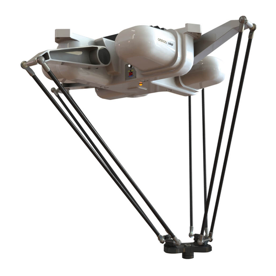
Chapter 1: Introduction Cable Inlet Box Mounting eAIB Pads Base Inner Inner Motor Cover Ball Joints (Spring Assemblies Outer not shown) Arms Platform Figure 1-1. Major Robot Components, Isometric View (650HS shown) eAIB The power amplifiers for the Quattro robot are embedded in the base of the robot. This amp- lifier section is known as the Amplifiers in Base (eAIB) distributed motion control platform, and provides closed-loop servo control of the robot amplifiers, as well as robot I/O. -
Page 14: Quattro Robot Base
Chapter 1: Introduction NOTE: The H and HS amplifiers and their cable inlet boxes are not inter- changeable. Quattro Robot Base The Quattro robot base is an aluminum casting that houses the four drive motors, and sup- ports the power amplifiers. It provides four mounting pads for attaching the base to a rigid support frame. -
Page 15: Platforms
Chapter 1: Introduction Ball Joint Ball Joint Stud Socket Inner Ball Joint Socket Insert Outer Arm Springs Pressed Spring Horseshoe Outer Arms Figure 1-3. Quattro Ball Joint Assembly, Quattro HS Robot shown Each pair of outer arms is held together with spring assemblies that pre-tension the ball joints. The outer arms can be installed and removed without tools. - Page 16 Chapter 1: Introduction P30 Platform (P/N 09730-xxx) The P30 platform is a fixed platform that provides no Theta rotation. The tool flange is machined into the one-piece platform. See P30 Platform, Electroless Nickel and Stainless Steel Versions on page 17. P32 Platform (P/N 09732-xxx) The P32 platform has a rotation range of ±92.5°.
- Page 17 Chapter 1: Introduction Figure 1-5. P30 Platform, Electroless Nickel and Stainless Steel Versions Model Number & Two Dots Figure 1-6. P32 Platform, Hard-Anodized Version NOTE: The only visible difference between the P32 and P34 platforms is the model number, and the two or four dots immediately below that number. Two dots des- ignate a P32 platform.
-
Page 18: Smartcontroller Ex
Chapter 1: Introduction Materials and Finishes Platforms are available in: Aluminum with hard-anodized finish Aluminum with electroless nickel finish Stainless steel The following table shows which materials and finishes are compatible with which robots: 650H 650HS 800H 800HS Part Number Hard XXXXX-000 Anodized... -
Page 19: Installation Overview
Chapter 1: Introduction Figure 1-7. SmartController EX Refer to the SmartController EX User’s Guide for SmartController specifications. 1.2 Installation Overview The system installation process is summarized in the following table. Also, refer to System Cable Diagram on page 69. NOTE: For dual-robot installations, see the Dual-Robot Configuration Procedure. Table 1-2. -
Page 20: How Can I Get Help
Install optional equipment, including end-effectors, End-Effectors on page 111. user air and electrical lines, external equipment, etc. 1.3 How Can I Get Help? For support or service, contact Omron Adept Technologies, Inc. refer to additional information sources on our corporate website: http://www.ia.omron.com Related Manuals This manual covers the installation, operation, and maintenance of an Quattro robot system. -
Page 21: Chapter 2: Safety
Chapter 2: Safety 2.1 Warnings, Cautions, and Precautions There are six levels of special alert notation used in our manuals. In descending order of importance, they are: DANGER: This indicates an imminently hazardous elec- trical situation which, if not avoided, will result in death or serious injury. -
Page 22: Safety Precautions
The robot system must not be used for purposes other than described in Intended Use of the Robots on page 24. Contact Omron Adept Technologies, Inc. if you are not sure of the suitability for your application. -
Page 23: Robot Behavior
Limiting Devices There are no dynamic or electro-mechanical limiting devices provided by Omron Adept Tech- nologies, Inc. The robot does not have safety-rated soft axis or space limiting. However, the user can install their own safety rated (category 0 or 1) dynamic limiting devices if needed, that comply with ISO 10218-1, Clause 5.12.2. -
Page 24: Intended Use Of The Robots
Chapter 2: Safety 2.6 Intended Use of the Robots DANGER: Quattros are not collaborative robots. They require a dedicated work area that will prevent personnel from coming into contact with them during operation. The normal and intended use of these robots does not create hazards. The Quattro has been designed and constructed in accordance with the relevant requirements of IEC 60204-1. -
Page 25: Chapter 3: Robot Installation - H
If the items received do not match the packing slip, or are damaged, do not sign the receipt. Contact Omron Adept Technologies, Inc. as soon as possible (see How Can I Get Help? on page 20). - Page 26 Chapter 3: Robot Installation - H NOTE: Outer arms for the Quattro 800 robot are packaged differently from the Quat- tro 650. Refer to Outer Arms for the Quattro 800 (800H shown) on page 26. Figure 3-1. Shipping Crate (650H shown) Figure 3-2. Outer Arms for the Quattro 800 (800H shown) The robot base is shipped with the inner arms attached.
-
Page 27: Repacking For Relocation
Chapter 3: Robot Installation - H 2. Lift off the cardboard sides. 3. Remove the lag bolts holding the robot base to the crate sides. 3.3 Repacking for Relocation If the robot or other equipment needs to be relocated, reverse the steps in the installation pro- cedures in this chapter. - Page 28 Figure 3-3. Sample Quattro Mounting Frame NOTE: More specifications for the sample frame are provided in Robot Mounting Frame, Quattro 650H Robot on page 138. Any robot’s ability to settle to a fixed point in space is governed by the forces, masses, and accelerations of the robot.
-
Page 29: Frame Orientation
Chapter 3: Robot Installation - H system. These disturbance forces cause “work” to be done by the robot servo control system which may result in longer settling times for robot operations. It is important to note that, even after the system reports the robot to be fully settled, the tool flange will still be moving by any amount of motion that the suspended base of the robot may be experiencing. -
Page 30: Gussets
Chapter 3: Robot Installation - H crane or forklift should be used to position the robot. If lifted from above, the robot must be lif- ted by user-supplied eyebolts and slings. Mounting Hole Dimensions, Quattro H Robots on page 118 shows the mounting hole pattern for the Quattro robot. -
Page 31: Mounting Options
Chapter 3: Robot Installation - H CAUTION: Failure to mount the Quattro robot within 0.75 mm of a flat plane will result in inconsistent robot motions. Mounting Options Using the mounting frame design provided, there are several options for mounting the Quattro robot: Lower the robot into the frame from above, or Lift the robot into the frame from below. - Page 32 Chapter 3: Robot Installation - H 8. Remove the slings and M16 eyebolts. 9. Follow the instructions in Install Mounting Hardware on page 33. Mounting to Bottom of Frame Pads NOTE: Since eyebolts would be in the way of this mounting method, you will have to use slings or other means to lift the robot base.
-
Page 33: Mounting Procedure From Below The Frame
Chapter 3: Robot Installation - H Mounting Procedure from Below the Frame The Quattro robot has four mounting pads. Each pad has one M16 x 2.0 threaded hole. The robot can be mounted either on top of the frame pads, using the bottom surface of the robot base pads, or to the bottom of the frame pads, using the top surface of the robot base pads. - Page 34 Chapter 3: Robot Installation - H 1. Place split lock, then flat washers on the bolts. Bolts are M16 x 2.0 if threaded into the robot base mounting tabs. Bolts are M12 or ½ in. if going through the robot base mounting tabs into nuts. NOTE: When M16 x 2.0 bolts are used, the bolt must engage at least 24 mm into the threads of the base mounting pad.
-
Page 35: Attaching The Outer Arms And Platform
Chapter 3: Robot Installation - H 3.7 Attaching the Outer Arms and Platform Cable Inlet Box Mounting eAIB Pads Base Inner Inner Motor Cover Ball Joints (Spring Assemblies Outer not shown) Arms Platform Figure 3-5. Major Robot Components, Top View The Quattro robot platform is attached to the inner arms by the outer arms. - Page 36 Chapter 3: Robot Installation - H On the hard-anodized and stainless steel platforms, the ends of the platform cross- pieces (between each pair of ball studs) are labeled with numbers (1–4). In addition, +X and +Y World Coordinates are labeled on the platform near the flange. See the following figure.
-
Page 37: Attaching The Outer Arms
Chapter 3: Robot Installation - H Tool Flange Figure 3-7. Platform Orientation, P31 Platform Attaching the Outer Arms One pair of outer arms attaches between each inner arm and the platform. No tools are needed to install or remove the outer arms. Each outer arm has a ball joint socket at each end. - Page 38 Chapter 3: Robot Installation - H Outer arm pairs are shipped assembled. Each pair has two springs and two horseshoes at each end. Ball Joint Ball Joint Stud Socket Inner Ball Joint Socket Insert Outer Arm Springs Pressed Spring Horseshoe Outer Arms Figure 3-9.
- Page 39 Chapter 3: Robot Installation - H This requires the least stretching of the spring to attach the ball joints. b. Slip one ball joint socket over the corresponding ball stud. c. Swing the bottom end of the outer arm pair sideways as you slip the other ball joint socket over the corresponding ball stud.
-
Page 40: Mounting The Front Panel
Chapter 3: Robot Installation - H Figure 3-11. Horseshoe and Spring Assembly 3.8 Mounting the Front Panel The Front Panel must be installed outside of the workspace. NOTE: European standards require that the remote High Power push-button be loc- ated outside of the workspace of the robot. Quattro User's Guide, 09955-000 Rev J Page 40 of 212... -
Page 41: Chapter 4: Robot Installation - Hs
If the items received do not match the packing slip, or are damaged, do not sign the receipt. Contact Omron Adept Technologies, Inc. as soon as possible. If the items received do not match your order, please contact Omron Adept Tech- nologies, Inc. immediately. - Page 42 NOTE: Outer arms for the Quattro 800HS robot are packaged differently from these illustrations. See the following two figures. Figure 4-1. Quattro Shipping Crate (Quattro 650H shown) Figure 4-2. View of crate with 800 Outer Arms (800H shown) The robot base is shipped with the inner arms attached. The outer arms are...
- Page 43 Chapter 4: Robot Installation - HS shipped assembled in pairs; the platform is shipped fully assembled, but sep- arate from the robot base and outer arms. Under the robot base, the ancillary items will be attached to the crate bottom. 2.
-
Page 44: Repacking For Relocation
Chapter 4: Robot Installation - HS 4.3 Repacking for Relocation If the robot or other equipment needs to be relocated, reverse the steps in the installation pro- cedures that follow in this chapter. Reuse all original packing containers and materials and fol- low all safety notes used for installation. -
Page 45: Frame Mounting Tabs
Chapter 4: Robot Installation - HS Frame Mounting Tabs (following) and Mounting Surfaces on page 54. The frame must be stiff enough to prevent excessive vibration. You may want to design the frame so that the robot can be installed by lowering it from the top. -
Page 46: Mounting
Chapter 4: Robot Installation - HS Mounting Mounting Hole Dimensions, Quattro HS Robots on page 119 shows the mounting hole pattern for the Quattro HS robot. Note the hole location and mounting pad tolerances for position and flatness. Deviation from this flatness specification will, over time, cause a possible loss of robot cal- ibration. - Page 47 Chapter 4: Robot Installation - HS Figure 4-4. Cable Inlet Box and Cover Components Cable Inlet box Cable Inlet box cover Cable Inlet box-cover gasket Cable Inlet box-eAIB gasket Compression Block kit - Roxtec CF 8-8 Roxtec CF 8 frame 4 x 2-hole Roxtec modules These are dense foam blocks surrounding pre-cut half-sleeves that can be peeled away to match the diameter of the cable to be sealed.
- Page 48 Chapter 4: Robot Installation - HS The following may be included as spares: 4 x Screws, M4 x 16 mm (for the cable tray) 4 x Washer seals (for the cable tray screws) 4 x Washers, ETL, SS M4 (for the cable tray) Tasks 1.
- Page 49 Chapter 4: Robot Installation - HS 2. Adapt Roxtec modules to fit the cables that will be used. There should be a 0.1 to 1.0 mm gap between the halves of the modules for a proper seal. See the following figure. Figure 4-6.
- Page 50 Chapter 4: Robot Installation - HS Figure 4-8. Installing Roxtec Modules into the Frame When all of the modules are in place, tighten the compression unit to 8 - 12 N·m (6 - 9 ft-lbf). See the following two figures. There should be no visible gaps between the modules or around the cables.
- Page 51 Chapter 4: Robot Installation - HS Figure 4-10. Cable Inlet Box with Cables In the preceding figure, note the four holes around the Roxtec box. These are for attaching a cable tray. See Attaching the Cable Tray on page 63. Quattro User's Guide, 09955-000 Rev J Page 51 of 212...
-
Page 52: Connecting The Cables
Chapter 4: Robot Installation - HS Connecting the Cables 1. Place the cable inlet box-eAIB gasket around the eAIB connection panel. 2. Attach the ground lug to the eAIB. The ground lug is for the cable shield of the user-sup- plied 24 VDC cable. - Page 53 Chapter 4: Robot Installation - HS Ground bolt and label Figure 4-12. Cable Inlet Box, showing Ground Label 2. Install the M4 protective earth ground bolt, with toothed washer, through the cable inlet box into the eAIB. See the preceding figure. Ensure that the protective earth ground wire lug is under the toothed washer.
-
Page 54: Mounting The Robot Base
Chapter 4: Robot Installation - HS 4.7 Mounting the Robot Base CAUTION: Remove all ancillary components (controller, outer arms, platform, etc.) from the shipping crate before lift- ing the robot base. Robot Orientation we recommend mounting the Quattro HS robot so that the Status Display Panel faces away from the conveyor belt. -
Page 55: Mounting Procedure From Above The Frame
Chapter 4: Robot Installation - HS Depending on the mounting frame design used, there may be two options for mounting the Quattro HS robot: Lower the robot into the frame from above Lift the robot into the frame from below CAUTION: Do not attempt to lift the robot from any points other than with slings as described here, or with a padded board, as described here. -
Page 56: Mounting Procedure From Below The Frame
Chapter 4: Robot Installation - HS Robot Base Raised Area (limits gasket compression) Sealing gasket Hole Figure 4-14. Robot Base Pad Sealing Gasket, Top View The area of the mounting pad surrounded by the groove serves as a spacer, to ensure that the sealing gasket is properly compressed. -
Page 57: Install Mounting Hardware
Chapter 4: Robot Installation - HS bottom surfaces of the frame mounting pads. 6. Follow the instructions in Install Mounting Hardware on page 57. Install Mounting Hardware To achieve the correct compression of the sealing gaskets, the mounting tabs on the frame must be 12.7 mm, +1.3, -0.7 mm (0.5 in., +0.05, -0.028 in.) thick. -
Page 58: Attaching The Outer Arms And Platform
Chapter 4: Robot Installation - HS The frame pads should completely cover the gaskets. Tighten the bolts to 98 N·m (74 ft-lb). NOTE: The robot base-mounting tabs have spring-lock HeliCoils in the M16 holes, so a lock washer is not needed on the M16 mounting bolts. NOTE: Check the tightness of the mounting bolts one week after initial installation, and then recheck every 3 months. -
Page 59: Clocking The Platform To The Base
Chapter 4: Robot Installation - HS NOTE: Except for attaching the outer arms and end-effector tooling, the platform is shipped fully assembled. Clocking the Platform to the Base The rotational alignment (clocking) of the platform to the base is critical to the correct oper- ation of the robot. -
Page 60: Attaching The Outer Arms
Chapter 4: Robot Installation - HS Attaching the Outer Arms One pair of outer arms attaches between each inner arm and the platform. No tools are needed. Each outer arm has a ball joint socket at each end. The inner arms and the platform have corresponding pairs of ball studs. Figure 4-18. - Page 61 Chapter 4: Robot Installation - HS Ball Joint Ball Joint Stud Socket Inner Ball Joint Socket Insert Outer Arm Springs Pressed Spring Horseshoe Outer Arms Figure 4-19. Ball Joint Assembly CAUTION: Ensure that the bearing insert is in place in the end of each outer arm.
- Page 62 Chapter 4: Robot Installation - HS b. Slip one ball joint socket over the corresponding ball stud. c. Swing the bottom end of the outer arm pair sideways as you slip the other ball joint socket over the corresponding ball stud. CAUTION: Do not overstretch the outer arm springs.
-
Page 63: Mounting The Front Panel
Chapter 4: Robot Installation - HS Figure 4-21. Horseshoe and Spring Assembly 4.9 Mounting the Front Panel The Front Panel must be installed outside of the workspace. NOTE: European standards require that the remote High Power push-button be loc- ated outside of the workspace of the robot. 4.10 Attaching the Cable Tray NOTE: The cable inlet box must be installed on the eAIB before the cable tray can be attached. - Page 64 Chapter 4: Robot Installation - HS Roxtec Frame 140.00 [5.512] Exterior 77.52 76.2 [3.05] [3.00] 44.45 [1.75] 170.82 [6.725] 7.95 4x M4 x 0.7 - 6H 7.87 [0.313] Units are mm [in.] [.31] Figure 4-22. Dimensions of Cable Tray Attachment to Cable Inlet Box Attach the cable tray to the cable inlet box, with a gasket between the two.
- Page 65 Chapter 4: Robot Installation - HS 4 x 7.4 [0.290 ] THRU 95.25 [3.75] 87.7 [3.45] 16.0 [0.63] 11.5 [0.45] 3.175 ± 0.076 168.4 [6.63] [0.125 ± 0.003] [0.313] 176.2 [6.94] [0.63] 184.2 [7.25] Units are mm [in.] Figure 4-23. Example Cable Tray Gasket NOTE: This cable-tray gasket is available as an option as part number 09751-000.
- Page 66 Chapter 4: Robot Installation - HS The following apply to the example cable tray. Item 1 Aluminum 5052-H32 Material Item 2 Aluminum 6061-T6 Clean part thoroughly using the fol- lowing process: Soak part in strong alkaline bath followed by light chemical clean Electroless nickel plate per MIL-C-2607E, Class 4, Finish Grade A...
- Page 67 Chapter 4: Robot Installation - HS PEM STANOFFS PROTRUDE THIS SIDE VIEW A-A 105.4 [4.15] 101.6 [4.00] R25.4 FILL GAP [R1.00] 95.3 95.3 [3.75] [3.75] 806.5 [31.75] 2.0° SEE FLAT PATTERN 184.2 (SHT. 2) FOR DETAIL [7.25] Units are mm [inches] OF THIS FLANGE Figure 4-26.
- Page 68 Chapter 4: Robot Installation - HS Figure 4-27. Sample Cable Tray, Dimension Drawing 2 Quattro User's Guide, 09955-000 Rev J Page 68 of 212...
-
Page 69: Chapter 5: System Installation
Chapter 5: System Installation 5.1 System Cable Diagram This chapter assumes you are not using a PLC. SmartController EX T20 Adapter Pendant Cable User-Supplied (optional) Ground Wire T20 Bypass Plug XMCP Jumper XUSR for: Either T20 Pendant, Plug - User E-Stop/Safety Gate T20 Bypass Plug, or Front XMCP Jumper Plug... -
Page 70: Cable Parts List
Chapter 5: System Installation 5.2 Cable Parts List Table 5-1. Cable Parts List Part Description Part of IEEE 1394 Cable, 4.5 M All systems eAIB XSYS Cable (eAIB), 4.5 M eAIB eAIB XSLV Adapter Cable (eAIB), AIB to eAIB upgrade 250 mm Front Panel Cable Front panel... -
Page 71: Pc Requirements
Chapter 5: System Installation PC Requirements The ACE disk will display a ReadMe file when inserted in your PC. This contains hardware and software requirements for running ACE software. 5.5 Installing ACE Software You install ACE from the ACE software disk. ACE needs Microsoft .NET Framework. The ACE Setup Wizard scans your PC for .NET, and installs it automatically if it is not already installed. -
Page 72: Description Of Connectors On Robot Interface Panel
Chapter 5: System Installation 5.6 Description of Connectors on Robot Interface Panel Figure 5-2. Robot Interface Panel 24 VDC—for connecting user-supplied 24 VDC power to the robot. The mating connector is provided. Ground Point—for connecting cable shield from user-supplied 24 VDC cable. 200-240 VAC—for connecting 200-240 VAC, single-phase, input power to the robot. -
Page 73: Cable Connections From Robot To Smartcontroller
Chapter 5: System Installation 5.7 Cable Connections from Robot to SmartController The following cables are shipped in the cable/accessories box. Locate the IEEE 1394 cable (length 4.5 M) Locate the eAIB XSYS cable or eAIB XSLV Adapter cable, which can be used with an existing XSYS cable. -
Page 74: Details For 24 Vdc Mating Connector
See the fol- lowing table for a recommended power supply. Table 5-3. Recommended 24 VDC Power Supply Mount Vendor Name Model Ratings OMRON S8JX-G15024C 24 VDC, 6.5 A, 150 W Front Mount OMRON S8JX-G15024CD 24 VDC, 6.5 A, 150 W... -
Page 75: Installing 24 Vdc Robot Cable
Chapter 5: System Installation 1. Locate the connector and pins shown in the preceding table. 2. Use 14-16 AWG wire to create the 24 VDC cable. Select the wire length to safely reach from the user-supplied 24 VDC power supply to the robot base. NOTE: A separate 24 VDC cable is required for the SmartController. -
Page 76: Connecting 200-240 Vac Power To Robot
Chapter 5: System Installation Quattro 650/800 Robot User-Supplied – Power Supply 24 VDC 24 V, 6 A – User-Supplied Shielded Frame Ground Power Cable Attach shield from user- supplied cable to ground 24 V, 5 A screw on robot interface –... -
Page 77: Specifications For Ac Power
Chapter 5: System Installation Specifications for AC Power Table 5-5. Specifications for 200-240 VAC User-Supplied Power Supply Auto-Ranging Minimum Maximum Frequency/ Recommended Nominal Operating Operating Phasing External Cir- Voltage Voltage Voltage cuit Breaker, Ranges User-Supplied 200 to 240 V 180 V 264 V 50/60 Hz 10 Amps... -
Page 78: Details For Ac Mating Connector
Chapter 5: System Installation voltage levels. Take the necessary steps to prevent damage to the robot system (for example, by interposing a transformer). See IEC 1131-4 for additional information. AC Power Diagrams Note: F1 is user-supplied, must be slow-blow. 1Ø F1 10 A 200–240 VAC 20 A... -
Page 79: Procedure For Creating 200-240 Vac Cable
Chapter 5: System Installation Table 5-6. AC Mating Connector Details AC Connector details AC in-line power plug, straight, female, screw ter- minal, 10 A, 250 VAC Qualtek P/N 709-00/00 Digi-Key P/N Q217-ND NOTE: The AC power cable is not supplied with the system. However, it is avail- able in the optional Power Cable kit. -
Page 80: Installing Ac Power Cable To Robot
Chapter 5: System Installation Figure 5-6. AC Power Mating Connector Installing AC Power Cable to Robot 1. Connect the AC power cable to your facility AC power source. See Typical AC Power Installation with Single-Phase Supply on page 78 and Single-Phase Load across L1 and L2 of a Three-Phase Supply on page 78. -
Page 81: Quattro Hs Robot Base
Chapter 5: System Installation Alignment Hole Mounting Hole Robot Ground Ground Hole Label Figure 5-7. Base Mounting Pad with Ground Hole, Top View Quattro HS Robot Base Because of the need to seal the junction between the robot base and the frame, the protective earth ground connection for the HS robots has been moved from the base mounting pad to inside the eAIB cable inlet box, which is electrically connected to the robot base. -
Page 82: Installing User-Supplied Safety Equipment
Chapter 5: System Installation NOTE: A ground strap from the end-effector to the base mounting pad must include a service loop that allows full rotation and movement of the tool flange. Quattro HS Robots Connect the robot cable inlet box protective earth ground. Ground the end-effector to the robot cable inlet box ground screw. - Page 83 Chapter 5: System Installation Description Comments Pairs 7, 20 E-Stop indication CH 1 Contacts are closed when Front Panel, pendant, and customer E-Stops are not tripped 8, 21 E-Stop indication CH 2 (same as Contacts are closed when Front Panel, pins 7, 20) pendant, and customer E-Stops are not tripped...
- Page 84 Chapter 5: System Installation Description Requirements for User- Pairs Supplied Front Panel Pin 1 Pin 8 Pin 15 Pin 9 See the figure System Installation on page 69 for a schematic diagram of the Front Panel. Users must exercise caution to avoid inadvertently connecting 24 V signals to these pins, because this will damage the electronics.
- Page 85 Chapter 5: System Installation ESTOP 24 V ESTOP Source Ground XSYSTEM-31 XSYSTEM-32 6 V, 1.2 W XSYSTEM-31 (XFP-6) (XFP-1) (XFP-2) Bulb XSYSTEM-3 (XFP-5) Front Panel High Power Front Panel XSYSTEM-33 (XFP-13) ON/OFF ESTOP XSYSTEM-34 (XFP-14) Pushbutton XSYSTEM-20 (XFP-10) (XFP-9) ESTOP 24 V Source (XPND-7) (XPND-6)
-
Page 86: Emergency Stop Circuits
Chapter 5: System Installation Front Panel Schematic ESTOPSRC 15PDSUBM ESTOPFP1 24 VS ESTOPFP2 MANUALSRC1 5 VD MANUALRLY1 MANUALSRC2 MANUALRLY2 HPLT5V HIPWRLT HIPWRREQ SYSPWRLT "System Power LED" "MANUAL/AUTO" "HIGH POWER ON/OFF" "EMERGENCY STOP" 5 VD HPLT5 V 24 VS ESTOPSRC MANUALSRC2 SYSPWRLT MANUALSRC1 2-PIN_MINI... - Page 87 ENABLE, or the Muted Safety gate. If you have a specific need in this area, contact Omron Adept Technologies, Inc. for information on alternate indicating modes. Two pairs of pins on the XUSR connector (pins 7, 20 and 8, 21) provide voltage-free contacts, one for each channel, to indicate whether the E-Stop chain, as described above, on that channel is closed.
-
Page 88: Remote Manual Mode
Chapter 5: System Installation CAUTION: If you want the cell gate to always cause a robot shutdown, wire the gate switch contacts in series with the user E-Stop inputs. Do not wire the gate switch into the muted safety gate inputs. Remote Manual Mode The Front Panel provides for a Manual Mode circuit. -
Page 89: Remote High Power On/Off Control
Chapter 5: System Installation Remote High Power On/Off Control The easiest and most effective way to provide the high power on/off control in a remote loc- ation is to mount the Front Panel in the desired location with an extension cable. However, if the user needs to control high power on/off from other control equipment or from a location other than the Front Panel, then a custom splitter cable will be required. -
Page 90: Remote Pendant Usage
Chapter 5: System Installation Customers can build an extension cable to place the Front Panel in a remote location. The extension cable must conform to the following specifications: Wire Size: must be larger than 26 AWG. Connectors: must be 15-pin, standard D-sub male and female. Maximum cable length is 10 meters. -
Page 91: Chapter 6: System Operation
Chapter 6: System Operation 6.1 Robot Status Display Panel The robot Status Display panel is located on the robot base. The Status Display and LED blink- ing pattern indicate the status of the robot. Figure 6-1. Robot Status Display Panels NOTE: The status codes and LED status indications are the same for both the Quat- tro H and Quattro HS robots. -
Page 92: Status Panel Fault Codes
Chapter 6: System Operation 2-Digit Status LED Status Description Panel Display Amber, Fast Blink Fault Code(s) Fault, see Status Display See Status Panel Fault Codes on page 1. 6.2 Status Panel Fault Codes The Status Display, shown in Robot Status Display Panels on page 91, displays alpha-numeric codes that indicate the operating status of the robot, including fault codes. -
Page 93: Using The Brake-Release Button
Chapter 6: System Operation 6.3 Using the Brake-Release Button Brakes The robot has a braking system which decelerates the robot in an emergency condition, such as when the emergency stop circuit is open or a robot joint passes its softstop. The standard braking system does not prevent you from moving the robot manually, once the robot has stopped (and high power has been disabled). -
Page 94: Front Panel
Chapter 6: System Operation If an alternate (user-supplied) brake release button is used, ensure that the brake release button displays a warning similar to the preceding WARNING. This is to comply with ISO 10218-1, Clause 5.13. 6.4 Front Panel NOTE: The factory-supplied Front Panel E-Stop is designed in accordance with the requirements of IEC 60204-1 and ISO 13849. -
Page 95: Connecting Digital I/O To The System
Chapter 6: System Operation WARNING: If an operator is going to be in the work cell in manual mode, it is strongly recommended that the operator carry an enabling device. The Enable button on the manual control pendant is such a device. WARNING: Whenever possible, manual mode operations should be performed with all personnel outside the work- space. -
Page 96: Using Digital I/O On Robot Xio Connector
Chapter 6: System Operation Quattro Robot sDIO #1 32 Input signals: 1033 to 1064 32 Output signals: 0033 to 0064 Optional IEEE-1394 *S/N 3563-XXXXX* XDC1 XDC2 LINK 0.5A sDIO #1 Optional SmartController EX XDIO Connector XSYSTEM ENET ENET 12 Input signals: 1001 to 1012 24 V XBELT Servo... - Page 97 Chapter 6: System Operation 12 Inputs, signals 1097 to 1108 8 Outputs, signals 0097 to 0104 Table 6-5. XIO Signal Designations Signal Pin Locations Designation Bank Signal Number 24 VDC Common 1 Input 1.1 1097 Pin 9 Input 2.1 1098 Pin 18 Pin 26 Input 3.1...
-
Page 98: Optional I/O Products
Chapter 6: System Operation Optional I/O Products These optional products are also available for use with digital I/O: XIO Breakout Cable, 5 meters long, with flying leads on user’s end. See XIO Breakout Cable on page 101 for information. This cable is not compatible with the XIO Ter- mination Block. - Page 99 Chapter 6: System Operation NOTE: The input current specifications are provided for reference. Voltage sources are typically used to drive the inputs. Typical Input Wiring Example User-Supplied Equipment Supplied Equipment Note: all Input signals Wiring can be used for either Typical User Terminal sinking or sourcing Input Signals...
-
Page 100: Xio Output Signals
Chapter 6: System Operation XIO Output Signals The eight digital outputs share a common, high side (sourcing) driver IC. The driver is designed to supply any kind of load with one side connected to ground. It is designed for a range of user-provided voltages, from 10 to 24 VDC, and each channel is capable of up to 0.7 A of current. -
Page 101: Xio Breakout Cable
Chapter 6: System Operation Typical Output Wiring Example Supplied Equipment User-Supplied Equipment Wiring Terminal Block +24 VDC Typical User Loads Signal 0097 (equivalent Signal 0098 circuit) Signal 0099 Signal 0100 Load Signal 0101 Load Signal 0102 Load Signal 0103 Customer Signal 0104 AC Power Supply... - Page 102 Chapter 6: System Operation Table 6-8. XIO Breakout Cable Wire Chart Signal Pin No. Designation Wire Color Pin Locations White 24 VDC White/Black Common 1 Input 1.1 Red/Black Pin 1 Input 2.1 Yellow Pin 10 Pin 19 Input 3.1 Yellow/Black Input 4.1 Green Input 5.1...
-
Page 103: Starting The System For The First Time
Chapter 6: System Operation 6.7 Starting the System for the First Time Follow the steps in this section to safely bring up your robot system. The tasks include: Verifying installation, to confirm that all tasks have been performed correctly Starting up the system by turning on power for the first time Verifying that all E-Stops in the system function correctly Moving the robot with the pendant (if purchased), to confirm that each joint moves cor- rectly... -
Page 104: Turning On Power And Starting Ace
Double-click the ACE icon on your Windows desktop, From the Windows Start menu bar, select: Start > Programs > Omron > ACE x.y. where x is the ACE major version, an y is the ACE monor version. For example, for ACE 3.6, it would be: Start > Programs > Omron > ACE 3.6... -
Page 105: Verifying E-Stop Functions
Chapter 6: System Operation 1. From the ACE main menu, click the Enable High Power icon: 2. If the High Power button on the Front Panel is blinking, press and release it. The Front Panel is shown in Front Panel on page 94. (If the button stops blinking, you must Enable Power again.) NOTE: The use of the blinking High Power button can be configured (or eliminated) in software. -
Page 106: Quattro Motions
Chapter 6: System Operation 6.8 Quattro Motions Straight-line Motion Joint-interpolated motion is not possible with the Quattro robot, because the positions of all the joints must always be coordinated in order to maintain the connections to the moving plat- form. Therefore, for the Quattro robot, the eV+ system automatically performs a straight-line motion when a joint-interpolated motion instruction is encountered. - Page 107 Chapter 6: System Operation accessed from the same direction. This motion can also be used to position the tool flange in preparation for the next motion. NOTE: When SINGLE is asserted, the tool flange will always rotate in the direction that does not cross the zero-roll position, even if that means a very large rotation. roll = -90 roll = +90 (A) Roll = -90 degrees...
- Page 108 Chapter 6: System Operation NOTE: When MULTIPLE is asserted, the tool flange will always rotate the smallest angle when the robot moves from one location to the next. roll = -90 roll = +90 (A) Roll = -90 degrees -180 +180 (B) Roll = 2 degrees Figure 6-9.
- Page 109 Chapter 6: System Operation robot moved into the overlap zone with SINGLE asserted. (But then, of course, a large rotation would have been done during the motion to location B.) roll = -90 roll = +90 (A) Roll = -90 degrees -180 +180 (B) Roll = 2 degrees (C) Roll = 4 degrees...
-
Page 110: Learning To Program The Quattro Robot
Chapter 6: System Operation When NOOVERLAP is set, the setting of SINGLE and MULTIPLE modes has no effect on the robot motion. 6.9 Learning to Program the Quattro Robot To learn how to use and program the robot, see the ACE User’s Guide, which provides inform- ation on robot configuration, control and programming through the ACE software “point and click”... -
Page 111: Chapter 7: Optional Equipment Installation
Chapter 7: Optional Equipment Installation 7.1 End-Effectors You are responsible for providing and installing any end-effector or other tooling, as well as vacuum lines and wiring to the end-effector. NOTE: For the Quattro 650HS robots, any end-effectors, tooling, and vacuum or elec- tric lines must conform to USDA regulations to maintain the robot’s USDA Accept- ance. -
Page 112: Routing End-Effector Lines
Chapter 7: Optional Equipment Installation 7.2 Routing End-effector Lines End-effector lines (either vacuum/air lines or electrical wires) can be routed to the platform by: Attaching them to the inner and outer arms, and then to the platform. Routing them from the robot support frame to the outer arms. Routing them from the robot base directly to the platform. -
Page 113: Ball Stud Locks
Chapter 7: Optional Equipment Installation 7.3 Ball Stud Locks Under abnormal or extreme loading conditions using very aggressive moves, or in the case of a collision, it is possible for the ball studs to separate from the ball joint sockets. NOTE: In normal use, this will not happen. -
Page 114: Installing A Ball Stud Lock
Chapter 7: Optional Equipment Installation Figure 7-2. Ball Stud Lock on Ball Joint Socket Installing a Ball Stud Lock The ball stud lock has a groove that mates with a lip around the end of the ball joint socket. 1. To install a ball stud lock, line up the groove in the ball stud lock with the lip in the ball joint socket, and slide the lock on. -
Page 115: Removing A Ball Stud Lock
Chapter 7: Optional Equipment Installation Removing a Ball Stud Lock To remove a ball stud lock, pull one end of the lock away from the ball joint socket. The lock will slide off (with resistance). No tools are needed. Figure 7-4. Removing a Ball Stud Lock Quattro User's Guide, 09955-000 Rev J Page 115 of 212... -
Page 117: Chapter 8: Technical Specifications
Chapter 8: Technical Specifications 8.1 Dimension Drawings 245.4 379.2 414.2 379.2 245.4 280.4 Robot C L Work Envelope C L 210.4 245.4 379.2 344.2 (Ø 1300) Work Volume Center of Robot to Platform Offset Center of Work Units are in mm Volume Offset in the X+ Direction P31, 32, 34... - Page 118 Chapter 8: Technical Specifications + .0006 [.01524] .3150 THRU - .0010 [.0254] [8.0] DETAIL C .551 [14.00] THRU M16 x 2.0 [50.8] - 6G THRU .709 [18.01] x 90°, NEAR SIDE .709 [18.01] x 90°, FAR SIDE +.0006 [.01524] .3150 - .0000 [8.0] 1.125 [28.58]...
- Page 119 Chapter 8: Technical Specifications 4X R.062 [1.57] +.0006 [.01524] EACH PAD .3150 - .0000 [8.0] 4.00 [101.60] [19.05] EACH PAD 4X M16x2.0 Helicoil insert x 24 mm 0.709 [18.01] x 90 ° DETAIL C R.47 [11.94] EACH PAD 2.00 [50.80] +.0006 [.01524] .3150...
- Page 120 Chapter 8: Technical Specifications 208.2 (650HS) 211.8 (650H) 700.0 (P30 Platform) 711.0 (P31 Platform) 727.6 (P32/P34 Platforms) Ø 700 Units are in mm Ø 1300 Figure 8-4. Work Envelope, Side View, Quattro 650 HS Shown 208.2 (800HS) 211.8 (800H) 1005.0 (P30 Platform) 1016.0 (P31 Platform) 1032.6 (P32/P34 Platforms) Ø...
- Page 121 Chapter 8: Technical Specifications Tool Flanges Both the P31 and P30 platforms have built-in tool flange faces (the tool flange face is actually machined into the strut or platform). The P31 tool flange face moves with the strut that it is part of, providing ± 46.25° of rotation. The P32 and P34 have tool flanges that rotate relative to the platform.
- Page 122 Chapter 8: Technical Specifications Ø 60 (2.35) 41.1 (1.62) 20.8 (0.820) Ø 6.0 (0.24) 6.0 (0.24) Ø 63.0 (2.48) 45.0° Ø 50 (2.0) B.C. 4x Ø 6.2 (0.25) 18.1 (0.71) Helicoils M6 x 1.0 x 12 mm long, Stainless Steel 4x 90.0°...
- Page 123 Chapter 8: Technical Specifications Quick-disconnect 4x M6 x 1.0 x 6 Helicoil Clamp-ring Groove 8.92 3x 90.00° 21.0 mm clearance +0.013 6.000 to platform 45.00° 25.0° 45 Chamfer 2x 45 Chamfer +0.025 62.992 41.148 0.254 18 Thru 66.80 59.690 5.671 1.499 Units are mm 11.767...
- Page 124 Chapter 8: Technical Specifications 132.10 66.04 215.9 55° 50° 241.30 113.19 Z = 0 171.27 17° Typical Inner Arm Travel Volume Units are mm Figure 8-9. Arm Travel Volume (650 shown) Quattro User's Guide, 09955-000 Rev J Page 124 of 212...
-
Page 125: Internal Connections
Chapter 8: Technical Specifications 8.2 Internal Connections Quattro eAIB Quattro Panel Internal Connections Connections Man 1 XSLV-2 (XSYSTEM 8) Man 2 XSLV-3 (XSYSTEM 38) Auto 1 XSLV-6 (XSYSTEM 14, 29) Auto 2 XSLV-7 (XSYSTEM 30, 44) To XSYS on SmartController ESTOPSRC XSLV-9 (XSYSTEM 16) Force-Guided Relay... -
Page 126: Robot Specifications
Chapter 8: Technical Specifications 8.4 Robot Specifications Specifications subject to change without notice. Table 8-3. Robot Specifications Description Specification Quattro 650 Quattro 650 SS Quattro 800 AL and EN Reach (cylinder radius) 650 mm (25.6 in.) 800 mm (31.5 in.) Payload - rated 2.0 kg (4.4 lb) 1.0 kg (2.2 lb) -
Page 127: Payload Specifications
Chapter 8: Technical Specifications Description Specification Quattro 650 Quattro 650 SS Quattro 800 AL and EN Footprint 883 x 883 mm (34.8 x 34.8 in.) The robot tool performs continuous path, straight-line motions 25 mm (1 in.) up, 305 or 700 mm (12/27.6 in.) over, 25 mm (1 in.) down, and back along the same path, at 20°... -
Page 128: Payload Mass Vs. Acceleration
Chapter 8: Technical Specifications Payload Mass vs. Acceleration To avoid excited vibrations, the following acceleration values are recommended for given tool payloads. Table 8-6. Payload Mass vs. Acceleration - 650 Quattro, Aluminum Platforms Platform Payload Maximum Acceleration Preferred Acceleration Type 15.0 12.0 10.0... -
Page 129: Payload Inertia Vs. Acceleration
Chapter 8: Technical Specifications Table 8-8. Payload Mass vs. Acceleration - 800 Quattro Platform Payload Maximum Acceleration Preferred Acceleration Type 10.0 17.6 23.5 11.8 39.2 15.7 58.8 23.5 109.8 11.2 47.0 113.7 11.6 62.7 117.6 12.0 62.7 120.0 12.2 62.7 % is the eV+ Accel/Decel setting, which, for the Quattro, can be set as high as 1000%. -
Page 130: Stopping Times And Distances
Chapter 8: Technical Specifications 8.6 Stopping Times and Distances NOTE: X and Y stopping distances and times are the same, so only X values are given in the following figures. X Stopping Distance (Quattro650 P34) Payload 33% Vmax 6.4m/s Payload 66% Vmax 6.3m/s Payload 100% Vmax 6.2m/s... - Page 131 Chapter 8: Technical Specifications Z Stopping Distance (Quattro650 P34) Payload 33% Vmax 4.1m/s Payload 66% Vmax 3.9m/s Payload 100% Vmax 3.9m/s Speed (%) Figure 8-13. Quattro 650 Z Stopping Distance with P34 Platform Z Stopping Time (Quattro650 P34) 0.15 Payload 33% Vmax 0.10 4.1m/s Payload 66% Vmax...
- Page 132 Chapter 8: Technical Specifications X Stopping Distance (Quattro650 P30) Payload 33% Vmax 6.6m/s Payload 66% Vmax 6.2m/s Payload 100% Vmax 6.2m/s Speed (%) Figure 8-15. Quattro 650 X Stopping Distance with P30 Platform X Stopping Time (Quattro650 P30) 0.15 Payload 33% Vmax 0.10 6.6m/s Payload 66% Vmax...
- Page 133 Chapter 8: Technical Specifications Z Stopping Distance (Quattro650 P30) Payload 33% Vmax 3.8m/s Payload 66% Vmax 3.8m/s Payload 100% Vmax 3.7m/s Speed (%) Figure 8-17. Quattro 650 Z Stopping Distance with P30 Platform Z Stopping Time (Quattro650 P30) 0.15 Payload 33% Vmax 0.10 3.8m/s Payload 66% Vmax...
- Page 134 Chapter 8: Technical Specifications X Stopping Distance (Quattro800 P34) Payload 33% Vmax 7.1m/s Payload 66% Vmax 7.1m/s Payload 100% Vmax 7.1m/s Speed (%) Figure 8-19. Quattro 800 X Stopping Distance with P34 Platform X Stopping Time (Quattro800 P34) 0.15 Payload 33% Vmax 0.10 7.1m/s Payload 66% Vmax...
- Page 135 Chapter 8: Technical Specifications Z Stopping Distance (Quattro800 P34) Payload 33% Vmax 3.8m/s Payload 66% Vmax 3.8m/s Payload 100% Vmax 2.9m/s Speed (%) Figure 8-21. Quattro 800 Z Stopping Distance with P34 Platform Z Stopping Time (Quattro800 P34) 0.15 Payload 33% Vmax 0.10 3.8m/s Payload 66% Vmax...
- Page 136 Chapter 8: Technical Specifications X Stopping Distance (Quattro800 P30) Payload 33% Vmax 7.3m/s Payload 66% Vmax 7m/s Payload 100% Vmax 7m/s Speed (%) Figure 8-23. Quattro 800 X Stopping Distance with P30 Platform X Stopping Time (Quattro800 P30) 0.15 Payload 33% Vmax 0.10 7.3m/s Payload 66% Vmax...
- Page 137 Chapter 8: Technical Specifications Z Stopping Distance (Quattro800 P30) Payload 33% Vmax 3.8m/s Payload 66% Vmax 3.8m/s Payload 100% Vmax 3.8m/s Speed (%) Figure 8-25. Quattro 800 Z Stopping Distance with P30 Platform Z Stopping Time (Quattro800 P30) 0.15 Payload 33% Vmax 0.10 3.8m/s Payload 66% Vmax...
-
Page 138: Robot Mounting Frame, Quattro 650H Robot
Chapter 8: Technical Specifications 8.7 Robot Mounting Frame, Quattro 650H Robot NOTE: The example frame provided here was not designed to meet USDA stand- ards. While most mechanical specifications are the same, you will have to make adjustments to comply with USDA requirements. - Page 139 Chapter 8: Technical Specifications SEE DETAIL 2 1800.0 2000.0 SEE DETAIL 1 SEE DETAIL 1 2000.0 MATERIAL SIZING: 150mm X 150mm X 6mm SQUARE STRUCTURAL TUBING UNLESS OTHERWISE SPECIFIED: 120mm X 120mm X 10mm SQUARE STRUCTURAL TUBING 250mm X 250mm X 15mm TRIANGULAR GUSSET * DIMENSIONS ARE IN MILLIMETERS MATERIAL : 300 SERIES STAINLESS STEEL Figure 8-27.
- Page 140 Chapter 8: Technical Specifications 2000.0 300.0 0.75 TOP & BOTTOM SURFACES OF PLATES 2000.0 UNLESS OTHERWISE SPECIFIED: * DIMENSIONS ARE IN MILLIMETERS Figure 8-28. Mounting Frame, Side View 1 1800.0 500.0 UNLESS OTHERWISE SPECIFIED: * DIMENSIONS ARE IN MILLIMETERS Figure 8-29. Mounting Frame, Side View 2 Quattro User's Guide, 09955-000 Rev J Page 140 of 212...
- Page 141 Chapter 8: Technical Specifications DETAIL 1 B 4x 90.0 580.0 300.0 46.2° 36.4° 275.0 25.0 180.0 MIN. 100.0 150.0 UNLESS OTHERWISE SPECIFIED: * DIMENSIONS ARE IN MILLIMETERS Figure 8-30. Mounting Frame, Detail 1 DETAIL 2 4x B 90.0 680.0 300.0 59.4°...
- Page 142 Chapter 8: Technical Specifications 2000.0 1000.0 520.0 290.0 430.0 245.41 379.18 19.50 THRU 18.50 45° 520.0 430.0 15.5 379.18 14.0 290.0 245.41 1800.0 245.41 290.0 379.18 430.0 520.0 900.0 379.18 245.41 430.0 290.0 UNLESS OTHERWISE SPECIFIED: 520.0 * DIMENSIONS ARE IN MILLIMETERS Figure 8-32.
-
Page 143: Chapter 9: Maintenance - H
Chapter 9: Maintenance - H NOTE: This chapter applies to the Quattro H robots (non-USDA) only. NOTE: Maintenance of user-added optional equipment is the user’s responsibility. It is not covered in this manual. 9.1 Periodic Maintenance Schedule Suggested Inspection on page 144 and Suggested Part Replacement on page 145 give a sum- mary of the preventive maintenance procedures and guidelines on frequency. - Page 144 Chapter 9: Maintenance - H Table 9-2. Suggested Inspection Est. Inspect/ Sugg. Suggested Insp. Inspection Check Interval Action Time User 1 Week 15 Min Inspect for wear around Replace cabling if cracked Cabling robot joints and possible or worn. Adjust cable pos- binding on robot.
- Page 145 Chapter 9: Maintenance - H Table 9-3. Suggested Part Replacement Estimated Suggested Item Time of Description Interval Maintenance Motor & 5 Years 1 Hour + Motor and geardrives are sold as a unit Gear Assembly Factory because damage to one often results in Calibration damage to both.
-
Page 146: Warning Labels
Chapter 9: Maintenance - H 9.2 Warning Labels NOTE: Labels giving instructions for lifting or installing are not considered warn- ing labels. They may be removed by the user, and do not need to be checked. All warning labels on the Quattro robot should be checked on a weekly basis for being present and legible. -
Page 147: Checking Safety Systems
Chapter 9: Maintenance - H Warning: Axes may fall due to gravity BRAKE RELEASE Figure 9-3. Brake Release/Gravity Label This label is located over the brake release button, on the status display panel. 9.3 Checking Safety Systems These tests should be done every six months. NOTE: Operating any of the following switches or buttons must disable high power. -
Page 148: Checking Fan Operation
Feel the bottom of the motors with your finger through the venting slots. 4. Check the outside of the motors and gear drives for any signs of oil. 5. Contact Omron Adept Technologies, Inc. if you find any signs of oil in these areas. 9.6 Checking Fan Operation The motor fans are PWM controlled. - Page 149 Chapter 9: Maintenance - H Lock out and tag out power. 6. Disconnect the XSYS cable from the chassis XSYS cable and eAIB XSLV Adapter cable from the chassis XSYSTEM connector. Disconnect the eXSYS cable (eAIB) from the chassis XSYSTEM connector. 7.
- Page 150 Chapter 9: Maintenance - H Figure 9-5. Opening the Chassis 12. Disconnect the white amplifier cable (motor power) from the amplifier connector located on the chassis bracket. See the following figure. Amplifier Connector ePMAI Board INT1 INT2 ENC1 ENC2 Figure 9-6. Connectors on eAIB Chassis and ePMAI Board Quattro User's Guide, 09955-000 Rev J Page 150 of 212...
-
Page 151: Installing A New Eaib Chassis
Chapter 9: Maintenance - H 13. Disconnect the cables from the INT1, INT2, ENC1, and ENC2 connectors on the ePMAI board by disengaging the securing latches. 14. Using a 5 mm hex key, disconnect and remove the cable shield ground wire from the chassis. -
Page 152: Commissioning A System With An Eaib
Chapter 9: Maintenance - H See Securing Bolt on Chassis on page 149. 9. If the robot will be used in the presence of chemicals that are caustic to aluminum, fol- low the instructions at Caustic Compatibility on page 198. External Connections 1. -
Page 153: Safety Commissioning Utilities
Chapter 9: Maintenance - H If the system will not power up in Manual mode, and the robot status display shows TR, you need to commission the system. Safety Commissioning Utilities The eAIB adds two functions that implement safety in hardware: E-Stop This serves as a backup to the standard software E-Stop process. -
Page 154: E-Stop Configuration Utility
Chapter 9: Maintenance - H Figure 9-8. Front Panel No E-Stops can be activated. For Configuration (E-Stop and Teach Restrict), the eAIB Commissioning Jumper must be plugged into the XBELTIO jack on the eAIB. NOTE: This is the only time that this jumper will be used. It is part number 11901-000, and must be removed for Verification and normal operation. -
Page 155: E-Stop Verification Utility
Chapter 9: Maintenance - H Procedure From within the ACE software: 1. Open the robot object editor. 2. Select Configure > Safety Settings > Configure ESTOP Hardware Delay, then click Next. This procedure will configure Channel A and then Channel B. It will then report the delay that it set for each. -
Page 156: Teach Restrict Verification Utility
Chapter 9: Maintenance - H Procedure NOTE: This procedure takes 2 or 3 minutes to complete. From within the ACE software: 1. Open the robot object editor. 2. Select Configure > Safety Settings > Configure Teach Restrict, then click Next. 3. From the Prerequisite screen, click Next. The wizard will go through all of the robot's motors, and display messages that it is con- figuring Channel A and B for each. -
Page 157: Replacing The Encoder Battery Pack
Chapter 9: Maintenance - H The screen will display the number of degrees that each joint is expected to move during the verification process. You can click Preview Motions on this screen to view the motions at slow speed. The default speed is 10, but you can change that speed with this screen's speed control. -
Page 158: Battery Replacement Interval
Chapter 9: Maintenance - H Battery Replacement Interval If the robot is kept in storage and not in use, or if the robot is turned off (no 24 VDC supply) most of the time, then the battery pack should be replaced every 5 years. If the robot is turned on, with 24 VDC supplied to the robot more than half the time, then you can increase the replacement interval to 10 years. - Page 159 Chapter 9: Maintenance - H Display panel with stand-offs. The battery pack is exposed when the Status Display panel is removed. 10. The battery bracket assembly has two connectors. Locate the unused battery connector on the battery bracket. See the following figure: Figure 9-11.
-
Page 160: Replacing A Platform
Chapter 9: Maintenance - H Take care that the “diag” cable is routed away from the eAIB fan inside the robot base. Be careful not to hit the top of the amber lamp with the back of the battery assembly. 9.10 Replacing a Platform CAUTION: Do not overstretch the outer-arm springs. -
Page 161: Replacing A Ball Joint Insert
Chapter 9: Maintenance - H From the ACE software: 1. Open the robot object editor. You can do this by double-clicking on the robot in the tree structure pane. 2. Click the Configure tab. 3. Select Load Spec File . . . 4. - Page 162 Chapter 9: Maintenance - H Figure 9-12. Removing an Outer Arm Spring Removing the first spring is the most difficult, as the other spring will tend to restrict movement of the spring. 2. Slip the springs off of the horseshoes. Refer to the following figure. Figure 9-13.
-
Page 163: Installing Outer Arm Spring Assemblies
Chapter 9: Maintenance - H Removing Outer Arm Spring Horseshoes NOTE: The only reason for removing an outer arm horseshoe is to replace one that has been damaged. 1. Remove the outer arm springs from the horseshoe. See the previous section. 2. - Page 164 Chapter 9: Maintenance - H Figure 9-15. End of Horseshoe on Pin 3. Squeeze the horseshoe the rest of the way, until it is over the pin. The horseshoe will snap into place. See the following figure. Figure 9-16. Squeezing the Horseshoe into Position Installing Springs on a Horseshoe 1.
-
Page 165: Changing The Lamp In The Front Panel High-Power Indicator
Chapter 9: Maintenance - H 2. Repeat for the remaining spring. Installing the last spring is the most difficult, as the other spring will tend to keep the spring from moving. 9.13 Changing the Lamp in the Front Panel High-Power Indicator The system is equipped with circuitry to detect the potentially dangerous condition of a burned-out High Power indicator on the Front Panel. - Page 166 Chapter 9: Maintenance - H 11. Push the front cover into the body, taking care to align all of the plug-type connectors. Verify that the wires do not get crimped as you reinstall the cover. 12. Re-install the two screws on the back of the body. 13.
-
Page 167: Chapter 10: Maintenance - Hs
Chapter 10: Maintenance - HS NOTE: This chapter applies to the Quattro HS robots only. NOTE: Maintenance and cleaning of user-added optional equipment is the user’s responsibility. It is not covered in this manual. NOTE: Some of the parts contained within the Quattro HS robots are not FDA-com- pliant, but are contained within another assembly that is. -
Page 168: Chemical Compatibility
Chapter 10: Maintenance - HS Table 10-2. Typical Cleaning Schedule, Raw Food Item Interval Suggested Cleaning Action Minimum: Entire Daily Clean In Place robot Optional: Platform Daily Clean Out of Place (dunk) Chemical Compatibility CAUTION: Not all materials used on the Quattro robot are compatible with all cleaning solutions available. -
Page 169: Periodic Maintenance
Chapter 10: Maintenance - HS Figure 10-1. Read Manual and Impact Warning Label Brake Release/Gravity Label, 18272-000 This label warns of the possibility of the platform dropping suddenly, due to gravity, when the brake release button is pressed. Warning: Axes may fall due to gravity BRAKE RELEASE... - Page 170 Chapter 10: Maintenance - HS WARNING: During maintenance, user-supplied fail-safe lock-out measures must be used to prevent unauthorized third parties from turning on power. This is mandated by Clause 5.2.4 of ISO 10218-1. NOTE: The estimated times listed in the following table are for the inspection, not the repair.
- Page 171 Chapter 10: Maintenance - HS Item Sugg. Est. Inspection Suggested Interval Time Action (Min) broken, seals. Inner arms: replace seals. E-Stop, 6 Mon 30 in Check functioning of E-Stops. Replace Front Enable and See Checking Safety Systems on page 172 Panel, or cus- tomer E-Stops.
-
Page 172: Checking Safety Systems
Chapter 10: Maintenance - HS Table 10-4. Suggested Part Replacement Item Suggested Estimated Description Interval Time of Maintenance Motor and 5 Years 1 Hour + Motor and geardrives are sold as a unit because Gear Factory damage to one often results in damage to both. Assembly Calibration Replacement interval is rated 5-10 years for most... -
Page 173: Checking Robot Mounting Bolts
Chapter 10: Maintenance - HS NOTE: Operating any of the following switches or buttons must disable high power. If any of the tests fail, repairs must be made before the robot is put back into operation. 1. Test operation of: E-Stop button on front panel E-Stop button on pendant Auto/Manual switch on front panel Enabling switch on pendant (Manual mode only) -
Page 174: Checking Fan Operation
5. Check the outside of the motors and gear drives for any signs of oil. 6. Contact Omron Adept Technologies, Inc. if you find any signs of oil in these areas. If you aren’t going to check the operation of the motor fans: 7. -
Page 175: Removing And Installing The Cable Inlet Box
Chapter 10: Maintenance - HS 5. Reinstall all motor covers. a. Ensure that the motor cover gaskets are in place. b. Use a washer seal on each bolt. c. Use Loctite 242 in the bolt holes, not on the bolts themselves. d. -
Page 176: Installing The Cable Inlet Box
Chapter 10: Maintenance - HS Installing the Cable Inlet Box 1. Place the cable inlet box-eAIB gasket around the eAIB connection panel. 2. Attach the cable shield ground lug to the eAIB. The ground lug is for the cable shield of the user-supplied 24 VDC cable. -
Page 177: Replacing The Eaib Chassis
Chapter 10: Maintenance - HS 10.9 Replacing the eAIB Chassis This section gives instructions on how to replace the eAIB chassis on an Quattro robot. CAUTION: Follow appropriate ESD procedures during the removal/replacement steps. Removing the eAIB Chassis 1. Switch OFF the SmartController. 2. - Page 178 Chapter 10: Maintenance - HS Lock out and tag out AC power. 8. Disconnect the XSYS cable from the chassis XSYS cable and eAIB XSLV Adapter cable from the chassis XSYSTEM connector Disconnect the eXSYS cable from the chassis XSYSTEM connector. 9.
-
Page 179: Installing A New Eaib Chassis
Chapter 10: Maintenance - HS Figure 10-5. Ground Screw Hole on eAIB Chassis 16. Remove the chassis from the robot, and set it aside. Tag it with the appropriate fault/error diagnosis and robot serial number information. Installing a New eAIB Chassis Harness Connections 1. -
Page 180: Commissioning A System With An Eaib
Chapter 10: Maintenance - HS External Connections 1. Connect the 200-240 VAC supply cable to the chassis AC input connector. 2. Connect the XSYS cable to the chassis XSYS cable and eAIB XSLV Adapter cable to the chassis XSYSTEM connector Connect the eXSYS cable (eAIB) to the chassis XSYSTEM connector. 3. -
Page 181: Safety Commissioning Utilities
Chapter 10: Maintenance - HS If the system will not power up in Manual mode, and the robot status display shows TR, you need to commission the system. Safety Commissioning Utilities The eAIB adds two functions that implement safety in hardware: E-Stop This serves as a backup to the standard software E-Stop process. -
Page 182: E-Stop Configuration Utility
Chapter 10: Maintenance - HS Figure 10-6. Front Panel No E-Stops can be activated. For Configuration (E-Stop and Teach Restrict), the eAIB Commissioning Jumper must be plugged into the XBELTIO jack on the eAIB. NOTE: This is the only time that this jumper will be used. It is part number 11901-000, and must be removed for Verification and normal operation. -
Page 183: E-Stop Verification Utility
Chapter 10: Maintenance - HS Procedure From within the ACE software: 1. Open the robot object editor. 2. Select Configure > Safety Settings > Configure ESTOP Hardware Delay, then click Next. This procedure will configure Channel A and then Channel B. It will then report the delay that it set for each. -
Page 184: Teach Restrict Verification Utility
Chapter 10: Maintenance - HS Procedure NOTE: This procedure takes 2 or 3 minutes to complete. From within the ACE software: 1. Open the robot object editor. 2. Select Configure > Safety Settings > Configure Teach Restrict, then click Next. 3. From the Prerequisite screen, click Next. The wizard will go through all of the robot's motors, and display messages that it is con- figuring Channel A and B for each. -
Page 185: Replacing The Encoder Battery Pack
Chapter 10: Maintenance - HS The screen will display the number of degrees that each joint is expected to move during the verification process. You can click Preview Motions on this screen to view the motions at slow speed. The default speed is 10, but you can change that speed with this screen's speed control. -
Page 186: Battery Replacement Interval
Chapter 10: Maintenance - HS Battery Replacement Interval If the robot is kept in storage and not in use, or if the robot is turned off (no 24 VDC supply) most of the time, then the battery pack should be replaced every 5 years. If the robot is turned on, with 24 VDC supplied to the robot more than half the time, then you can increase the replacement interval to 10 years. - Page 187 Chapter 10: Maintenance - HS Figure 10-8. Status Display Panel, Showing 8 Hex-head Bolts 9. Remove the Status Display panel. Retain the Status Display panel cover and gasket for reinstallation. NOTE: The battery pack is supported in a bracket that is attached to the back side of the Status Display panel with stand-offs.
- Page 188 Chapter 10: Maintenance - HS 11. Connect the new battery pack to the unused connector on the battery bracket, but do not disconnect the old battery pack. There is only one way to plug in the connector. See Battery Bracket on Status Display Panel on page 188.
-
Page 189: Replacing A Platform
Chapter 10: Maintenance - HS Ensure that the Status Display panel cover is in place over the panel. Ensure that a washer seal is in place under each bolt. Torque the bolts to 1.1 N·m (10 in-lb). 10.12 Replacing a Platform CAUTION: Do not overstretch the outer-arm springs. -
Page 190: Configuration
Chapter 10: Maintenance - HS Configuration If the replacement platform has the same part number as the old platform, the robot does not need to be reconfigured. If the replacement platform is a different type of platform, for instance, replacing a 185° plat- form with a P31 platform, the new configuration needs to be loaded using ACE software. -
Page 191: Replacing Outer Arm Spring Assemblies
Chapter 10: Maintenance - HS WARNING: Dry ice can cause burns if touched. Wear well- insulated gloves when you handle the dry ice. You may want to wear lighter gloves to handle the cold inserts. 1. Remove the old insert. a. If the insert is held tightly, you can facilitate its removal by packing the insert with dry ice. - Page 192 Chapter 10: Maintenance - HS Figure 10-11. Removing an Outer Arm Spring, H Shown Removing the first spring is the most difficult, as the other spring will tend to restrict movement of the spring. 2. Slip the springs off of the horseshoes. See the following figure. Figure 10-12.
-
Page 193: Installing Outer Arm Spring Assemblies
Chapter 10: Maintenance - HS The narrowest part of the horseshoe is 90° from the groove in which the spring end normally rests. 3. Repeat these steps for the remaining spring. Removing Outer Arm Spring Horseshoes NOTE: The only reason for removing an outer arm horseshoe is to replace one that has been damaged. - Page 194 Chapter 10: Maintenance - HS Figure 10-14. End of Horseshoe on Pin, H Shown 3. Squeeze the horseshoe the rest of the way, until it is over the pin. See the following fig- ure. The horseshoe will snap into place. Figure 10-15. Squeezing the Horseshoe into Position, H Shown Installing Springs on a Horseshoe 1.
-
Page 195: Replacing The Front Panel
Chapter 10: Maintenance - HS Installing the last spring is the most difficult, as the other spring will tend to keep the spring from moving. 10.15 Replacing the Front Panel The procedure for this is the same as for the Quattro H. Refer to Changing the Lamp in the Front Panel High-Power Indicator on page 165. -
Page 197: Chapter 11: Robot Cleaning/Environmental Concerns- H
Chapter 11: Robot Cleaning/ Environmental Concerns- H NOTE: The SmartController must be installed inside a NEMA-1 rated enclosure. The rest of this chapter applies to the non-USDA Accepted Quattro robot, not to the SmartCon- troller. The Quattro robot is designed to be compatible with standard cleaning and operational needs for secondary food packaging, as well as less stringent requirements. -
Page 198: Cleaning
11.3 Cleanroom Classification The Quattro robot is rated for cleanroom class 1000. Please contact Omron Adept Technologies, Inc. for more information. 11.4 Design Factors Environmental and cleaning aspects are addressed by the following features in the Quattro robot. -
Page 199: Inner Arms
For the Quattro 800H robots, these platforms are available in hard-anodized or electroless nickel finishes. For the Quattro 650H, they are also available in stainless steel. All platforms are designed to meet the basic criteria of wipe down compatibility and long life. -
Page 200: Installing Cable Seal Kit
Chapter 11: Robot Cleaning/ Environmental Concerns- H 11.5 Installing Cable Seal Kit NOTE: The Quattro 650H cable seal kit is not USDA compliant. Drainage of wash- down from the cable seal assembly does not comply with USDA requirements. Refer to the Quattro 650HS robot. - Page 201 Chapter 11: Robot Cleaning/ Environmental Concerns- H 2. Install the cable seal housing on the top of the eAIB using four M4 x 50 screws, four M4 lock washers, and four M4 flat washers. Note that the centered M6-threaded hole must be toward the center of the robot base.
- Page 202 Chapter 11: Robot Cleaning/ Environmental Concerns- H Figure 11-3. Bottom of Cable Entry Top Cover, CF Frame 3. Adapt Roxtec modules to fit the cables that will be used by peeling out half-circle strips from the modules. There should be a 0.1 to 1.0 mm gap between the halves of the mod- ules for a proper seal.
- Page 203 Chapter 11: Robot Cleaning/ Environmental Concerns- H Figure 11-5. Greasing a Roxtec Module 5. Grease the inside of the CF frame, where the modules will touch, using Roxtec grease. 6. Install each eAIB cable through its corresponding module, and insert the modules into the frame.
- Page 204 Chapter 11: Robot Cleaning/ Environmental Concerns- H Figure 11-8. Cable Entry Assembly with Cables 8. Attach the ground lug to the eAIB. The ground lug is for the cable shield of the user-sup- plied 24 VDC cable. See the following figure. Quattro User's Guide, 09955-000 Rev J Page 204 of 212...
- Page 205 Chapter 11: Robot Cleaning/ Environmental Concerns- H Figure 11-9. eAIB Panel Showing Ground Point 9. Hand-tighten all cables to the eAIB. NOTE: All cables must be screwed into the eAIB. 10. Attach the cable entry top cover, with Roxtec frame and modules, to the eAIB cable seal housing.
- Page 206 Chapter 11: Robot Cleaning/ Environmental Concerns- H Figure 11-10. Installing Cable Entry Top Cover Assembly Quattro User's Guide, 09955-000 Rev J Page 206 of 212...
- Page 207 Chapter 12: Environmental Concerns - HS NOTE: The SmartController must be installed inside a NEMA-1 rated enclosure. The rest of this chapter applies to the Quattro HS robot, not to the SmartController. The Quattro HS robot is designed to be compatible with standard cleaning and operational needs for the handling of raw, unpackaged meat and poultry products, as well as less strin- gent requirements.
- Page 208 The inserts generally produce few wear particulates. The material used in the inserts is FDA-compliant. Lubrication of the ball joints is not needed. Acidic Operating Conditions Refer to Chemical Compatibility on page 168. Contact Omron Adept Technologies, Inc. for more information. Quattro User's Guide, 09955-000 Rev J...
- Page 209 650HS or 800HS robot. All four platform types are also available in stainless steel for the 650HS. All platforms are designed to meet the basic criteria of wash-down compatibility and long life. Please contact Omron Adept Technologies, Inc. for more information. Quattro User's Guide, 09955-000 Rev J Page 209 of 212...
- Page 212 OMRON ADEPT TECHNOLOGIES, INC. No. 438A Alexandra Road # 05-05/08 (Lobby 2), 4550 Norris Canyon Road, Suite 150, San Ramon, CA 94583 U.S.A. © OMRON Corporation 2016 All Rights Reserved. Alexandra Technopark, Tel: (1) 925-245-3400/Fax: (1) 925-960-0590 In the interest of product improvement,...
Need help?
Do you have a question about the Quattro 650H and is the answer not in the manual?
Questions and answers