Stryker Renaissance Series Operation Manual
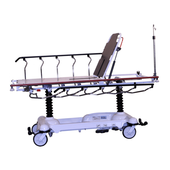
Emergency care stretcher
Hide thumbs
Also See for Renaissance Series:
- Maintenance manual (85 pages) ,
- Maintenance manual (196 pages)

Related Manuals for Stryker Renaissance Series


Summary of Contents for Stryker Renaissance Series
- Page 1 Renaissance Series 1212 Emergency Care Stretcher Operations Manual For Parts or Technical Assistance 800–327–0770...
-
Page 2: Table Of Contents
Table of Contents Introduction ..............Specifications . -
Page 3: Introduction
Introduction INTRODUCTION This manual is designed to assist you with the operation of the 1212 Emergency Care Stretcher. Read it thor- oughly before using the equipment or beginning any maintenance on it. SPECIFICATIONS Maximum Weight Capacity 500 pounds Overall Bed Length \ Width 83 1/2”... -
Page 4: Operating Three-Sided Controls Base
Stretcher Operation OPERATING THREE–SIDED CONTROLS BASE FOOT END Pump to raise litter. Depress to lower head end. Depress to lower foot end. Brake and Steer functions (control end). Brake and Steer functions (non–control end). -
Page 5: Operating Four-Sided Controls Base
Stretcher Operation OPERATING FOUR–SIDED CONTROLS BASE FOOT END Pump to raise litter. Depress to lower head end. Depress to lower foot end. Brake and Steer functions. -
Page 6: Raising And Lowering Litter Height
Stretcher Operation RAISING AND LOWERING LITTER HEIGHT NOTE For user convenience, there are two stretcher bases available: a ”three–sided” base with pump pedals and control pedals on both sides of the stretcher and on the foot or head end and a ”four–sided” base with pump pedals and control pedals on both sides and on both ends. -
Page 7: Applying The Brake System
Stretcher Operation APPLYING THE BRAKE SYSTEM NOTE For user convenience, the Brake/Steer pedal is located on both ends of the stretcher on both ”three–sided” and ”four–sided” control stretchers. CAUTION If brakes do not hold properly, refer to your stretcher maintenance manual for ”Brake Adjustment” To engage the brakes on the non–control end of a ”three–sided”... -
Page 8: Operating Fowler And Knee Gatch
Stretcher Operation OPERATING THE FOWLER/KNEE GATCH NOTE There are two types of Fowler options: 1) crank operated, 2) pneumatic operated. The choice was made at the time the stretcher was purchased. A crank Knee Gatch is also optional. Crank Fowler/Crank Knee Gatch: Turn crank handle (A) clockwise to raise Fowler, counterclockwise to lower. -
Page 9: Using Siderails
Stretcher Operation USING SIDERAILS NOTE Raising and lowering siderails is a two–handed operation. Use one hand to hold and position the siderail and the other hand to operate the siderail latch. WARNING When lowering the siderail to the collapsed position, keep extremities of patients and staff away from the side- rail spindles. -
Page 10: Operating Optional 2-Stage Permanently Attached I.v. Pole
Stretcher Operation OPERATING OPTIONAL 3–STAGE PERMANENTLY ATTACHED I.V. POLE NOTE An optional 3–stage permanently attached I.V. Pole may have been installed at either the head, foot or both ends of the stretcher. The choice was made at the time the stretcher was purchased. To use the 3–stage permanently attached I.V. -
Page 11: Operating Optional 3-Stage Permanently Attached I.v. Pole
Stretcher Operation OPERATING OPTIONAL TETHERED I.V. POLE To use the tethered I.V. pole: 1. Remove the I.V. pole from the storage trough under the litter and insert into the receptacle on the corner of the litter frame. 2. To raise the height of the pole, turn knob (A) counterclockwise and pull up on the telescoping portion (B) of the pole to raise it to the desired height. -
Page 12: Operating Optional X-Ray Cassette Holder
Stretcher Operation USING OPTIONAL X–RAY CASSETTE HOLDER 1. To access the Fowler x–ray cassette holder, raise the Fowler section. 2. Grasp handles (A) and squeeze, allowing locating pins (B) to disengage from mounting brackets (C). 3. Lower tray and install x–ray cassette. 4. -
Page 13: Operating Optional Heel Stirrups
Stretcher Operation OPERATING OPTIONAL HEEL STIRRUPS 1. To use the optional heel stirrups, turn the handle (A) on the lock screw located under the litter frame and swing the stirrup assembly into position. Tighten the handle (A) to hold the assembly in place. 2. -
Page 14: Preventative Maintenance
These products are corrosive in nature and may cause dam- age to your stretcher if used improperly. If these types of products are used to clean Stryker patient handling equipment, measures must be taken to insure the stretchers are rinsed with clean water and thoroughly dried following cleaning. -
Page 15: Limited Warranty
If requested by Stryker, products or parts for which a warranty claim is made shall be returned prepaid to Stryker’s factory. -
Page 16: Return Authorization
Claim will be limited in amount to the actual replacement cost. In the event that this information is not received by Stryker within the fifteen (15) day period following the delivery of the merchandise, or the damage was not noted on the delivery receipt at the time of receipt, the customer will be responsible for pay- ment of the original invoice in full. - Page 17 6300 Sprinkle Road, Kalamazoo, MI 49001–9799 (800) 327–0770 DH 7/94 1212–90–1 REV __...
Need help?
Do you have a question about the Renaissance Series and is the answer not in the manual?
Questions and answers