
Related Manuals for Stryker Surgistool 830


Summary of Contents for Stryker Surgistool 830
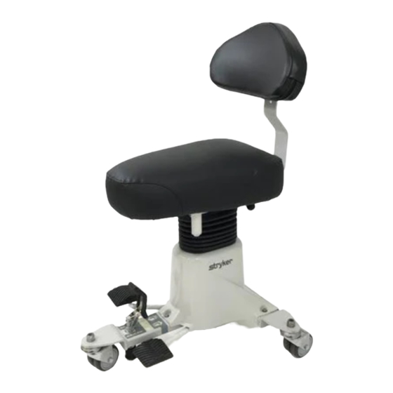
- Page 1 Operations/ Maintenance Medical Manual Surgistool Model 830 Important Information File in your For parts or technical maintenance assistance call records 800 327 0770 (option 2)
-
Page 2: Table Of Contents
Table of Contents Introduction Specifications ................Warning / Caution / Note Definition . -
Page 3: Introduction
28.5 − 21 inches Upper/Lower Height Range w/2” Riser Kit 30.5 − 23 Inches Stryker reserves the right to change specifications without notice. WARNING / CAUTION / NOTE DEFINITION The words WARNING, CAUTION and NOTE carry special meanings and should be carefully reviewed. -
Page 4: Base Pedal Operation
Operation Guide BASE PEDAL OPERATION SIDE VIEW (A) Push down to set Surgistool brake. Lift up to release brake. (B) Pump to raise Surgistool height. (C) Depress to lower Surgistool height. Back to Table of Contents... -
Page 5: Adjusting The Back Rest
Operation Guide ADJUSTING THE BACK REST To adjust the height of the back rest, turn knob (A) counterclockwise. Slide the back rest up or down to the desired height. Turn knob (A) clockwise and tighten until the back rest is secure. To move the back rest closer to the seat or farther away from the seat, turn knob (B) counterclockwise. -
Page 6: Preventative Maintenance
Preventative maintenance should be performed at a minimum of annually. A preventative maintenance pro- gram should be established for all Stryker Medical equipment. Preventative maintenance may need to be performed more frequently based on the usage level of the product. -
Page 7: Cleaning
100 parts water are not considered mild detergents. These products are corrosive in nature and may cause damage if used improperly. If these types of products are used to clean Stryker equipment, measures must be taken to insure the unit is rinsed with clean water and thoroughly dried following cleaning. -
Page 8: Hydraulic System Troubleshooting
Remove excess air (vacuum) in system (see below). If the jack still will not pump up, replace jack. Contact Stryker technical support at 1−800−327−0770 for further assistance. REMOVING EXCESS AIR (VACUUM) FROM THE HYDRAULIC SYSTEM 1. Pump the jack completely up and continue to pump the pedal after the jack reaches the top. This will force the air through the system and the jack should now pump up. -
Page 9: Checking Hydraulic Fluid Level
7. The hydraulic fluid should be visible at the bottom of the fill hole. If it is not, add Mobil Aero HFA hydraulic fluid (Stryker part number 2020−70−475) until the fluid is visible at the bottom of the fill hole. Replace the fill plug. -
Page 10: Base Hood Removal
Service Information BASE HOOD REMOVAL Required Tools: Standard Screwdriver 7/16” Open End Wrench 5/32” Allen Wrench Bungee Cords or String Procedure: 1. Using a standard screwdriver, pop off the 3 black plastic caps covering the screws holding on the base hood, being careful not to damage the caps. -
Page 11: Quick Reference Replacement Parts List
Quick Reference Replacement Parts List PART NAME PART NUMBER Brake Assembly ............830−10−450 Brake Tip . -
Page 12: Seat To Base Assembly
Seat to Base Assembly, Round & Obround Seat Assembly part numbers 830−20−101 (Round) & 830−30−101 (Obround) (reference only) (ROUND SEAT SHOWN) Item Part No. Part Name Qty. (page Seat Assembly 16−28 Nylock Nut 11−63 Flat Washer 4−193 Hex Soc. But Hd. Cap Scr. (page 16 &... -
Page 13: Motorcycle Seat To Base Assembly
Seat to Base Assembly, Motorcycle Seat Assembly part number 830−201−20 (reference only) Item Part No. Part Name Qty. (page Motorcycle Seat Assembly 16−28 Nylock Nut 11−63 Flat Washer 4−193 But. Hd. Cap Screw (page 16 & Hydraulic Base Assembly 830−90−4 Name Plate 921−1−252 Serial No. -
Page 14: Round & Obround Seat Assembly
830−20−100/830−30−100 Seat Assembly, Round/Obround Item Part No. Part Name Qty. 830−20−30 Seat Bracket Weldment 830−20−34 Backrest Support Bar 830−20−35 Clamp Weldment 830−20−38 Wear Strip 830−20−28 Female Hinge 830−20−26 Male Hinge and Pin 830−20−27 Flat Hd. Carriage Bolt 24−45 T−Handle, Female 24−44 T−Handle, Male 12−12... -
Page 15: Motorcycle Seat Assembly
830−201−100 Motorcycle Seat Assembly Item Part No. Part Name Qty. Item Part No. Part Name Qty. 830−20−30 Seat Bracket Weldment 763−201−29 Seat & Mtg. Hardware 830−20−34 Backrest Support Bar 830−20−20 Back Rest Assembly 830−20−35 Clamp Weldment 830−91−3 Rotation Label 830−20−38 Wear Strip 38−278 Compression Spring... - Page 16 Notes Back to Table of Contents...
-
Page 17: Base Assembly
830−10−100 Base Assembly Back to Table of Contents... -
Page 18: Jack Assembly
37−55 Protective Cap 16−64 Nylock Nut 4−135 But. Hd. Cap Screw 830−10−35 Brake Tip 37−56 Retaining Washer 830−10−34 Foot 946−1−60 Stryker Logo Label 11−3 Flat Washer 830−90−1 Rear Label 14−21 Flat Washer 830−90−2 Front Label 15−12 830−90−6 Pump Label 763−1−33 Brake Nut 830−90−7... - Page 19 830−10−70 Jack Assembly Item Part No. Part Name Qty. 48−13 Needle Valve 48−146 90° Adjustable Elbow 390−2−147 L−Fitting 763−20−23 Return Line 763−20−34 Replacement Valve Ass’y (page Jack Assembly 830−10−71 Pressure Line Back to Table of Contents...
- Page 20 Jack Assembly Assembly part number 830−10−60 ( reference only) Item Part No. Part Name Qty. Item Part No. Part Name Qty. 45−904 Quad Ring 830−10−62 Actuator Cylinder 715−1−340 Machined Cap 390−2−139 Retaining Collar 390−1−243 Gasket 390−2−136 Pump Cylinder 390−2−137 Pump Cap 390−1−237 Pump Gasket (page...
- Page 21 926−1−295 Jack Base Assembly Item Part No. Part Name Qty. 946−1−291 Jack Base 926−20−154 Seal 926−20−153 Check Valve 926−20−156 Seal 926−20−159 Valve Plug 926−20−157 Base Plug 926−20−155 Seal 926−20−152 Check Valve 926−20−158 Reservoir Plug Back to Table of Contents...
-
Page 22: Pump Pedal Assembly
830−10−130 Pump Pedal Assembly Item Part No. Part Name Qty. 830−10−131 Pump Pedal Assembly 11−271 Washer 715−1−126 Pedal Pad 946−1−155 Bumper 2−18 Rd. Hd. Machine Screw Back to Table of Contents... -
Page 23: Release Pedal Assembly
830−10−20 Release Pedal Assembly Item Part No. Part Name Qty. 830−10−21 Release Pedal Ass’y 11−271 Washer 715−1−126 Side Control Pedal Pad 946−1−155 Bumper 2−18 Rd. Hd. Machine Screw Back to Table of Contents... -
Page 24: Brake Assembly
830−10−10 Brake Assembly Item Part No. Part Name Qty. 830−10−15 Mounting Block 830−10−14 Actuator Shaft 830−10−11 Pedal Assembly 830−10−13 Lever Arm 716−1−275 Brake Pedal 25−106 Semi−Tubular Rivet 25−113 Semi−Tubular Rivet 26−215 Dowel Pin 38−279 Compression Spring 11−286 Flat Washer A complete brake assembly (including the brake tip and foot, not shown here) is part number 830−10−450. The brake tip and foot assembly (not shown here) is part number 830−10−451. -
Page 25: Optional Back Rest Assembly
830−700−1 Optional Backrest Assembly Item Part No. Part Name Qty. Item Part No. Part Name Qty. 830−20−34 Backrest Support Bar 12−12 Lockwasher 830−20−35 Clamp Weldment 4−161 H. Soc. But. Hd. Cap Scr. 12 830−20−38 Wear Strip 14−20 Nylon Washer 830−20−28 Female Hinge 11−54 Flat Washer... -
Page 26: Optional Wrist Rest Assembly
830−40−100 Optional Wrist Rest Assembly Spacer Assembly (No Wrist Rests) Item Part No. Part Name Qty. Item Part No. Part Name Qty. 830−40−30 Wrist Rest Pad Ass’y 3−21 Hex Hd. Cap Screw 830−40−10 Wrist Rest Weldment 11−262 Washer 4−193 Hex Soc. But. Hd. Cap Scr. 830−40−201 Spacer 24−44... -
Page 27: Optional Seat Riser Assembly
830−201−28 Optional 2” Seat Riser Assembly Item Part No. Part Name Qty. 4−161 Button Hd. Cap Screw 11−63 Flat Washer 16−28 Nylock Nut 830−21−13 Seat Riser Back to Table of Contents... -
Page 28: Limited Warranty
If requested by Stryker, products or parts for which a warranty claim is made shall be returned prepaid to Stryker’s factory. Any improper use or any alteration or repair by others in such manner as in Stryker’s judgement affects the product materially and adversely shall... -
Page 29: Return Authorization
Stryker will perform all service during regular business hours (9−5) * Replacement parts and labor for products under PM contract will be discounted. ** Does not include any disposable items, I.V. poles (except for Stryker HD permanent poles), mattresses, or damage re- sulting from abuse. - Page 30 European Representative Stryker EMEA RA/QA Director Stryker France ZAC Satolas Green Pusignan Av. De Satolas Green 69881 MEYZIEU Cedex France 3800 E. Centre Ave., Portage, MI 49002 (800) 327−0770 www.stryker.com 2011/12 0830−090−020 REV W.1...
Need help?
Do you have a question about the Surgistool 830 and is the answer not in the manual?
Questions and answers