Stryker MX-PRO R3 Operation & Maintenance Manual
Ambulance cot
Hide thumbs
Also See for MX-PRO R3:
- Operation manual (40 pages) ,
- Operation & maintenance manual (115 pages)

Related Manuals for Stryker MX-PRO R3


Summary of Contents for Stryker MX-PRO R3
- Page 1 MX-PRO ® 6082 Operations/Maintenance Manual 2013/02 A.0 6082-209-001 REV A www.stryker.com...
-
Page 3: Table Of Contents
Stryker EMS Return Policy ........ - Page 4 Patient Right Assembly, No I.V. Pole Option - 6080-212-010 ......... 6082-209-001 REV A www.stryker.com...
- Page 5 Quick Reference Replacement Part List ............www.stryker.com...
-
Page 6: Introduction
Stryker reserves the right to change specifications without notice. The MX-PRO is designed to conform to the Federal Specification the Star-of-Life Ambulance KKK-A-1822-F. The yellow and black color scheme is a proprietary trademark of Stryker Corporation. Return To Table of Contents 6082-209-001 REV A www.stryker.com... -
Page 7: Warning / Caution / Note Definition
NOTE Provides special information to make maintenance easier or important instructions clearer. Return To Table of Contents www.stryker.com 6082-209-001 REV A... -
Page 8: Product Illustration
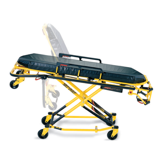
Transport Wheels Wheel Lock (Optional) Figure 2 − 6082 MX−PRO R3 Cot Transport Wheels Long Safety Hook Short Safety Hook Stryker part number Stryker part number 6060−036−018 6060−036−017 J Safety Hook Stryker part number 6092−036−018 Return To Table of Contents 6082-209-001 REV A www.stryker.com... -
Page 9: Symbols And Definitions
Symbols and Definitions Warning, consult accompanying documentation Safe Working Load Symbol Manufacturer Return To Table of Contents www.stryker.com 6082-209-001 REV A... -
Page 10: Warranty
(1) year after date of delivery. Stryker’s obligation under this warranty is expressly limited to supplying replacement parts and labor for, or replacing, at its option, any product that is, in the sole discretion of Stryker, found to be defective. -
Page 11: Stryker Ems Return Policy
Claim will be limited in amount to the actual replacement cost. In the event that this information is not received by Stryker within the fifteen (15) day period following the delivery of the merchandise, or the damage was not noted on the delivery receipt at the time of receipt, the customer will be responsible for payment of the original invoice in full. -
Page 12: Summary Of Safety Precautions
• Failure to properly clean or dispose of contaminated mattress or cot components will increase the risk of exposure to bloodborne pathogens and may cause injury to the patient or the operator. Return To Table of Contents 6082-209-001 REV A www.stryker.com... - Page 13 CAUTION • Height limit kit is recommended for ambulance deck heights less than 30 inches (76 cm) − Stryker part number 6060−202−000. • Damage to the cot can occur if the cot is lowered in the shortened position. Use only positions 5−7 (see page 19) when the cot is shortened.
-
Page 14: Setup Procedures
• Does the vehicle safety hook engage the safety bar so that the cot loads and unloads easily from the vehicle? • Is there an approved crash−stable fastener (Stryker part number 6370/6377/6378 or 6371 − not included) installed in the vehicle? The patient compartment of the vehicle in which the Cot will be used must have: • A smooth rear edge for cot loading. -
Page 15: Vehicle Safety Hook Selection
Federal Regulation KKK-A-1822. Stryker offers three different types of safety hooks that are ordered and shipped with your ambulance cot. These safety hook types are designed to meet the needs of various emergency vehicle configurations, specifically the length and location of the floor structure support that is located in the rear of the vehicle. -
Page 16: Vehicle Safety Hook Installation
* The length of the socket head cap screws depends on the thickness of the vehicle floor. Use screws that are long enough to go completely through the patient compartment floor, washer and nut by at least two full threads. Return To Table of Contents 6082-209-001 REV A www.stryker.com... -
Page 17: Front To Back Positioning Of The Safety Hook
• To avoid injury, verify that the safety bar has engaged the safety hook before removing the cot from the patient compartment. Note: Stryker recommends that, prior to installation, the certified mechanic plan the placement of the safety hook in the rear of the vehicle. -
Page 18: Side To Side Positioning Of The Safety Hook
Verify that the cot legs lock into the load position before disengaging the safety bar from the safety hook. Failure to properly lock the cot into position can cause injury to the patient or operator and/or damage to the cot. Return To Table of Contents 6082-209-001 REV A www.stryker.com... -
Page 19: Cot Positions
Use only positions 5-7 when using this configuration. Position 5 - Use for patient transfer/cot rolling. Return To Table of Contents www.stryker.com 6082-209-001 REV A... -
Page 20: Cot Operations
Figures 7 and 8. The arrows indicate alternate attachment areas. Figure 8 - Foot Section Restraints Return To Table of Contents 6082-209-001 REV A www.stryker.com... - Page 21 Any restraint showing wear or not operating properly must be replaced immediately. Figure 11 - Shortening the Safety Restraint Return To Table of Contents www.stryker.com 6082-209-001 REV A...
-
Page 22: Pedi-Mate® Infant Restraint System Attachment Instructions (Optional Equipment)
Figure 13 - Fastening the Pedi-Mate® Buckle WARNING To avoid accidental release of the Pedi-Mate®, and possible injury to the infant, ensure the buckle is located away from obstructions on the cot or head end storage pouch. Return To Table of Contents 6082-209-001 REV A www.stryker.com... - Page 23 • These are general instructions for installation of the Pedi-Mate®. Safe and proper use of the Pedi-Mate® is solely at the discretion of the user. Stryker recommends all users be trained on the proper use of the Pedi-Mate® before using it in an actual situation.
-
Page 24: Operating Guidelines
Both users must lift weight up off the base. The user at the foot end must pull the release handle. Both users must lower the cot to the ground or raise the cot up. Return To Table of Contents 6082-209-001 REV A www.stryker.com... -
Page 25: Loading The Cot Into A Vehicle With Two Operators
6. Both Operators − Push the cot into the patient compartment (Figure 18), engaging the cot fastener (not included). Figure 18 − 2 Operators − Base Full Up Figure 18 - 2 Operators - Base Full Up Return To Table of Contents www.stryker.com 6082-209-001 REV A... -
Page 26: Loading An Empty Cot Into A Vehicle With One Operator
10. Push the cot into the patient compartment, guiding it into the cot fastener. Figure 20 - Lower the Foot End of the Cot Figure 21 - Pull Up the Base of the Cot Return To Table of Contents 6082-209-001 REV A www.stryker.com... -
Page 27: Unloading The Cot From A Vehicle With Two Operators
Disengage the safety bar from the safety hook by pushing the safety bar release lever forward and roll the cot out of the vehicle. Return To Table of Contents www.stryker.com 6082-209-001 REV A... -
Page 28: Using Additional Assistance
Operator Operators Helpers Operator Helper Helper Helper Operator Helper Operator Helper Helper Helper Helper Operator Operator Operator Operator Helper Operators Four Helpers Helper Helper Operator Helper Helper Helper Helper Helper Operator Return To Table of Contents 6082-209-001 REV A www.stryker.com... -
Page 29: Operating The Optional Wheel Lock(S)
6” diameter could compromise the holding ability of the wheel lock, possibly resulting in injury to the patient or operator and/or damage to the cot or other equipment. Return To Table of Contents www.stryker.com 6082-209-001 REV A... -
Page 30: Adjusting The Wheel Locking Force
Insert the sleeve into the pedal. Reinstall the socket screw. Test the pedal locking force and verify the pedal holds properly before returning the cot to service. Return To Table of Contents 6082-209-001 REV A www.stryker.com... -
Page 31: Changing The Cot Height With Two Operators
Grasping the cot improperly can cause injury. Grasp only the litter frame or the lifting bar to lift the cot. Keep hands, fingers and feet away from moving parts. To avoid injury, use extreme caution when placing your feet near the base tubes while raising and lowering the cot. Return To Table of Contents www.stryker.com 6082-209-001 REV A... -
Page 32: Changing The Height Of An Empty Cot With One Operator
If lowering the cot to the lowest position (position 1), remove your foot from the base tube or injury could result (Figure 28). Figure 28 - Lowering Cot From Side Figure 27 - Holding Outer Support Rail Return To Table of Contents 6082-209-001 REV A www.stryker.com... -
Page 33: Adjusting The Leg Rest
To lower the leg rest, lift the leg rest frame (A) and, while holding the frame, lift up on the release handle (B) until the bracket disengages. Lower the leg rest until flat. Return To Table of Contents www.stryker.com 6082-209-001 REV A... -
Page 34: Operating The Backrest
Siderails are not intended to serve as a patient restraint device. Refer to page 20 for proper restraint strap usage. Failure to utilize the siderails properly could result in patient injury. Return To Table of Contents 6082-209-001 REV A www.stryker.com... -
Page 35: Operating The Breakaway Head Section
To raise the breakaway head section, lift the breakaway head section until the release bar clicks and the head section locks into place. CAUTION Damage to the cot can occur if the cot is lowered in the shortened position. Use only positions 5−7 (see page when the cot is shortened. Return To Table of Contents www.stryker.com 6082-209-001 REV A... -
Page 36: Operating The Two-Stage I.v. Pole (Optional Equipment)
Turn the lock actuator (B) clockwise to lock the telescoping portion in place. Hang I.V. bags on the I.V. hook (D). CAUTION The weight of the I.V. bags or equipment must not exceed 40 pounds. Return To Table of Contents 6082-209-001 REV A www.stryker.com... -
Page 37: Operating The Three-Stage I.v. Pole (Optional Equipment)
The weight of the I.V. bags or equipment must not exceed 40 pounds. Figure 35 - Three-Stage I.V. Pole Storage Position Figure 36 − 3−Stage I.V. Pole Figure 36 - Three-Stage I.V. Pole Return To Table of Contents www.stryker.com 6082-209-001 REV A... -
Page 38: Cleaning
24 inches/61 cm from the unit. • Towel dry all casters and interface points. • After washing the cot, follow the lubrications procedure on page • Failure to comply with these instructions may invalidate any/all warranties. Return To Table of Contents 6082-209-001 REV A www.stryker.com... -
Page 39: Removal Of Iodine Compounds
• SOME CLEANING PRODUCTS ARE CORROSIVE IN NATURE AND MAY CAUSE DAMAGE TO THE PRODUCT IF USED IMPROPERLY. If the products described above are used to clean Stryker patient care equipment, measures must be taken to insure the cots are wiped with a cloth soaked in clean water and thoroughly dried following cleaning. -
Page 40: Preventative Maintenance
_____ Foot rest operating properly _____ No rips or cracks in mattress cover _____ Body restraints intact and working properly _____ Lubricate base tubes (optional) Serial Number: Completed by: _______________________________________ Date: _________________ Return To Table of Contents 6082-209-001 REV A www.stryker.com... -
Page 41: Base Lubrication
Using the plastic applicator tube, spray Tri−Flow™ with Teflon ® lubricant (Stryker part number 6082−199−12) in the gap between the upper (item A) and lower lift tubes (item B) on both foot end legs. Apply Tri−Flow™ to right and left height adjustment... -
Page 42: Pneumatic Backrest Adjustment
If the backrest drifts down, turn the set screw (item H) counterclockwise. Repeat until the backrest does not drift downward. Using the 1/2” wrench, tighten the hex nut (item F) while holding the set screw (item H) fixed in the pivot. Return To Table of Contents 6082-209-001 REV A www.stryker.com... -
Page 43: Maintenance Record
Maintenance Record Date Maintenance Operation Performed Hours Return To Table of Contents www.stryker.com 6082-209-001 REV A... -
Page 44: Training Record
Training Record Training Date Training Method Trainee Name Basic Refresher Owner’s Manual, In-Service, Training Update Formal Class, Etc. Return To Table of Contents 6082-209-001 REV A www.stryker.com... -
Page 45: Cot Assembly
Cot Assembly 6082-150-011 Rev P (Reference Only) Return To Table of Contents www.stryker.com 6082-209-001 REV A... - Page 46 Cot Assembly Return To Table of Contents 6082-209-001 REV A www.stryker.com...
- Page 47 Cot Assembly Return To Table of Contents www.stryker.com 6082-209-001 REV A...
- Page 48 Cot Assembly Return To Table of Contents 6082-209-001 REV A www.stryker.com...
- Page 49 Cot Assembly Return To Table of Contents www.stryker.com 6082-209-001 REV A...
- Page 50 Blind Rivet 6082-090-043 Label, Stryker 6060-090-004 Label, Small 6060-090-114 Label, Keep Hands Clear 6070-090-107 Label, Lift to Release 6082-090-045 Label, MX-PRO R3 6080-090-108 Label, Lift Here 6080-090-009 Label, Warning 6082-090-110 Label, MX−PRO R3 6082-090-040 Label, MX-PRO Tube, Left 0946-001-155 Bumper...
-
Page 51: Base Assembly
Base Assembly 6082-101-011 Rev G (Reference Only) Return To Table of Contents www.stryker.com 6082-209-001 REV A... - Page 52 Base Assembly LEFT HAND OPTION SHOWN RIGHT HAND OPTION SHOWN Return To Table of Contents 6082-209-001 REV A www.stryker.com...
- Page 53 Base Assembly Return To Table of Contents www.stryker.com 6082-209-001 REV A...
- Page 54 6082-039-000 Rev A Standard Height 6082-040-000 Rev A Extended Height 6082-105-057 Height Adj. Rack, Left CA 6082-343-082 Height Adj. Rack, Right BB 6082-305-052 Height Adj. Rack, Right CB 6082-343-083 Height Adj. Rack, Left Return To Table of Contents 6082-209-001 REV A www.stryker.com...
-
Page 55: Wheel Assembly - 6060-002-010
Wheel Assembly - 6060-002-010 Rev B Item Part No. Part Name Qty. 6060-002-045 6 In Molded Wheel 6060-002-046 Bearing Spacer 0081-226-000 Bearing 0715-001-255 Wheel Bushing Return To Table of Contents www.stryker.com 6082-209-001 REV A... -
Page 56: Base Pivot Outer Lift Tube Assembly - 6082-201-067
Base Pivot Outer Lift Tube Assembly - 6082-201-067 Rev B Item Part No. Part Name Qty. 0025-079-000 Dome Head Pop Rivet 6085-001-112 Inner Leg Bumper 6082-101-057 Base Pivot Outer Lift Tube Weldment 1 6085-001-126 Hot Drop Dampener Retainer Return To Table of Contents 6082-209-001 REV A www.stryker.com... -
Page 57: Base Pivot Inner Lift Tube Assembly - 6082-001-069
Base Pivot Inner Lift Tube Assembly - 6082-001-069 Rev A Item Part No. Part Name Qty. 6082-001-059 Inner Lift Tube Weldment 0025-079-000 Blind Rivet 6082-101-035 Hot Drop Dampener 6082-001-036 Hot Drop Dampener Sleeve Return To Table of Contents www.stryker.com 6082-209-001 REV A... -
Page 58: Lock Bar Assembly - 6082-005-056
Lock Bar Assembly - 6082-005-056 Rev - Item Part No. Part Name Qty. 0028-181-000 Truarc Ring 6082-005-055 Height Adjustment Rack Lock Bar 6082-005-065 Lock Bar Slide Plate 6082-005-096 Height Adjustment Rack Latch Pin 0081-248-000 Bearing Return To Table of Contents 6082-209-001 REV A www.stryker.com... -
Page 59: Adjustable Caster Lock Assembly - 6082-200-010
Caster Horn 6080-100-032 Spring 0011-456-000 Washer 0025-153-000 Semi-Tubular Rivet 6080-090-101 Label, Warning 6080-300-030 Adjustable Caster Lock Pedal 6080-200-041 Octagonal Sleeve 0004-098-000 Hex Socket Button Head Cap Screw 1 0016-118-000 Centerlock Nut Return To Table of Contents www.stryker.com 6082-209-001 REV A... -
Page 60: Optional Single Wheel Lock Assembly - 6082-501-010
Adj. Caster Lock Assembly (page 59) 1 Optional Dual Wheel Lock Assembly - 6082-502-010 Rev B Item Part No. Part Name Qty. 6082-200-010 Adj. Caster Lock Assembly (page 59) 2 6082-002-012 Caster Horn Assembly Return To Table of Contents 6082-209-001 REV A www.stryker.com... -
Page 61: No Wheel Lock Option
6082-200-010 Adj. Caster Lock Assembly (page 59) 2 Four Wheel Lock Option 6082-504-010 Rev A (Reference Only) Item Part No. Part Name Qty. 6082-200-010 Adj. Caster Lock Assembly (page 59) 4 Return To Table of Contents www.stryker.com 6082-209-001 REV A... -
Page 62: Caster Horn Assembly
Caster Horn Assembly 6082-002-012 Rev C (Reference Only) Item Part No. Part Name Qty. 6082-002-039 Bearing Retainer 0081-227-000 Bearing 6082-002-042 Caster Horn Plate, Left 6082-002-043 Caster Horn Plate, Right Return To Table of Contents 6082-209-001 REV A www.stryker.com... -
Page 63: Litter/Base Adapter Assembly, Right - 6082-205-050
Litter/Base Adapter Assembly, Right - 6082-205-050 Rev A Item Part No. Part Name Qty. 6082-005-034 Adapter Mounting Bracket, Right 6082-005-051 Adapter Pivot Tube 0037-225-000 Hole Plug 0025-079-000 Blind Rivet Return To Table of Contents www.stryker.com 6082-209-001 REV A... -
Page 64: Litter/Base Adapter Assembly, Left - 6082-205-053
Litter/Base Adapter Assembly, Left - 6082-205-053 Rev A Item Part No. Part Name Qty. 6082-005-035 Adapter Mounting Bracket, Left 6082-005-051 Adapter Pivot Tube 0037-225-000 Hole Plug 0025-079-000 Blind Rivet Return To Table of Contents 6082-209-001 REV A www.stryker.com... -
Page 65: Litter Assembly
Litter Assembly 6082-130-011 Rev K (Reference Only) Return To Table of Contents www.stryker.com 6082-209-001 REV A... - Page 66 Litter Assembly Return To Table of Contents 6082-209-001 REV A www.stryker.com...
- Page 67 Litter Assembly Return To Table of Contents www.stryker.com 6082-209-001 REV A...
- Page 68 Litter Assembly Return To Table of Contents 6082-209-001 REV A www.stryker.com...
- Page 69 Litter Assembly Return To Table of Contents www.stryker.com 6082-209-001 REV A...
- Page 70 Litter/Base IF Pivot Spacer 6082-032-045 Fowler Skin 6082-032-050 Fowler Weldment 6082-032-052 Fowler Lift Release Handle 6082-033-032 Slide Plate, Left 6082-033-033 Slide Plate, Right 6082-034-046 Midsection Skin 6082-038-031 Calf Stand Support, Left Return To Table of Contents 6082-209-001 REV A www.stryker.com...
- Page 71 Label, Warning Extended Height Litter Stop Option - 6082-042-000 Rev B Item Part No. Part Name Qty. 0004-135-000 Button Head Cap Screw 6082-343-081 Extended Litter Stop 6082-090-114 Label, Keep Hands Clear Return To Table of Contents www.stryker.com 6082-209-001 REV A...
-
Page 72: Siderail Assembly - 6082-026-010
Top Rail 6060-025-043 Spindle 6060-025-047 Spindle Lock 6060-025-041 Spindle Pivot 6060-025-040 Spindle Pivot Stop 6060-025-029 Lock Release Grip 6061-125-030 Lock Bar Casting 0038-344-000 Lock Release Compression Spring 6060-025-035 Pivot Bushing 0025-131-000 Rivet Return To Table of Contents 6082-209-001 REV A www.stryker.com... -
Page 73: Optional Lift Tube Assembly, Left Side Release - 6082-140-059
Optional Lift Tube Assembly, Left Side Release - 6082-140-059 Rev B Return To Table of Contents www.stryker.com 6082-209-001 REV A... - Page 74 6082-040-025 Link Bushing, End 6082-040-061 Release Handle Assy. (page 6082-130-038 Litter Stop, Foot End 6082-140-030 Lift Brace 6082-240-053 Lift Tube Assy., with Grips, Upper 6082-240-054 Lift Tube Assy., with Grips, Lower Return To Table of Contents 6082-209-001 REV A www.stryker.com...
-
Page 75: Optional Lift Tube Assembly, Right Side Release - 6082-140-060
Optional Lift Tube Assembly, Right Side Release - 6082-140-060 Rev B Return To Table of Contents www.stryker.com 6082-209-001 REV A... - Page 76 Link Bushing, End 6082-040-029 Pull Handle Link 6082-040-062 Release Handle (page 6082-130-038 Litter Stop, Foot End 6082-140-030 Lift Brace 6082-140-057 Lift Tube Assy., with Grips, Upper 6082-140-058 Lift Tube Assy., with Grips, Lower Return To Table of Contents 6082-209-001 REV A www.stryker.com...
-
Page 77: Release Handle Assembly, Left - 6082-040-061
Release Handle Assembly, Left - 6082-040-061 Rev A Item Part No. Part Name Qty. 0025-127-000 Rivet 6082-001-081 Release Handle 6082-140-034 Release Handle Brace Return To Table of Contents www.stryker.com 6082-209-001 REV A... -
Page 78: Release Handle Assembly, Right - 6082-040-062
Release Handle Assembly, Right - 6082-040-062 Rev A Item Part No. Part Name Qty. 0025-127-000 Rivet 6082-001-081 Release Handle 6082-140-035 Release Handle Brace Return To Table of Contents 6082-209-001 REV A www.stryker.com... -
Page 79: Breakaway Head Assembly
Breakaway Head Assembly 6080-037-055 Rev J (Reference Only) Return To Table of Contents www.stryker.com 6082-209-001 REV A... - Page 80 6082-037-042 Pivot, Form Right 6082-037-043 Pivot, Form, Left 6082-037-057 Grooved Clevis Pin Assembly 6090-037-039 Trigger Lock 6500-001-321 Safety Bar Torsion Spring 6500-001-323 Pivot, Safety Hook, Right 6500-001-324 Pivot, Safety Hook, Left Return To Table of Contents 6082-209-001 REV A www.stryker.com...
- Page 81 Breakaway Head Assembly - Standard Components - 6080-037-010 Rev K (Reference Only) Item Part No. Part Name Qty. 0014-067-000 Nylon Flat Washer 0025-079-000 Dome Head Rivet 0028-138-000 Retaining Ring 6080-036-025 Pivot Pin 6080-036-047 Crossbar, Release, Bent 6080-037-055 Breakaway Head Section Return To Table of Contents www.stryker.com 6082-209-001 REV A...
- Page 82 Qty. 6082-037-040 Center Pivot, Head Section Breakaway Head Assembly - Extended Height Option - 6082-038-000 Rev A (Reference Only) Item Part No. Part Name Qty. 6082-343-085 Center Pivot, Ext, Head Section Return To Table of Contents 6082-209-001 REV A www.stryker.com...
- Page 83 Breakaway Head Assembly Breakaway Head Assembly - Lift Option - 6091-156-016 Rev C (Reference Only) Item Part No. Part Name Qty. 6080-037-024 Breakaway Head Section Safety Bar 1 Return To Table of Contents www.stryker.com 6082-209-001 REV A...
-
Page 84: Optional Two-Stage I.v. Pole Assembly, Right - 6080-210-010
0004-097-000 Button Head Cap Screw 0004-163-000 Button Head Cap Screw 0004-163-000 Button Head Cap Screw 0004-198-000 Button Head Cap Screw 0004-198-000 Button Head Cap Screw 0016-102-000 Nylock Nut 0016-102-000 Nylock Nut Return To Table of Contents 6082-209-001 REV A www.stryker.com... -
Page 85: Optional Two-Stage I.v. Pole Assembly, Right - 6080-210-020
Item Part No. Part Name Qty. 6070-090-105 Label, Caution 6070-210-070 Two-Stage I.V. Pole Assembly (page 6080-090-031 Label, Specification 6080-210-053 I.V. Socket Weldment, Right 6070-110-037 I.V. Pivot Pin 0025-079-000 Dome Head Rivet Return To Table of Contents www.stryker.com 6082-209-001 REV A... -
Page 86: Optional Three-Stage I.v. Pole Assembly, Right - 6080-215-020
Item Part No. Part Name Qty. 6070-090-105 Label, Caution 6070-215-070 Three-Stage I.V. Pole Assembly (page 6080-090-033 Label, Specification 6080-210-053 I.V. Socket Weldment, Right 6070-110-037 I.V. Pivot Pin 0025-079-000 Dome Head Rivet Return To Table of Contents 6082-209-001 REV A www.stryker.com... -
Page 87: Optional Two-Stage I.v. Pole Assembly, Left - 6080-211-010
0004-097-000 Button Head Cap Screw 0004-163-000 Button Head Cap Screw 0004-163-000 Button Head Cap Screw 0004-198-000 Button Head Cap Screw 0004-198-000 Button Head Cap Screw 0016-102-000 Nylock Nut 0016-102-000 Nylock Nut Return To Table of Contents www.stryker.com 6082-209-001 REV A... -
Page 88: Optional Two-Stage I.v. Pole Assembly, Left - 6080-211-020
Item Part No. Part Name Qty. 6070-090-105 Label, Caution 6070-210-070 Two-Stage I.V. Pole Assembly (page 6080-090-032 Label, Specification 6080-211-053 I.V. Socket Weldment, Left 6070-110-037 I.V. Pivot Pin 0025-079-000 Dome Head Rivet Return To Table of Contents 6082-209-001 REV A www.stryker.com... -
Page 89: Optional Three-Stage I.v. Pole Assembly, Left - 6080-216-020
Item Part No. Part Name Qty. 6070-090-105 Label, Caution 6070-215-070 Three-Stage I.V. Pole Assembly (page 6080-090-034 Label, Specification 6080-211-053 I.V. Socket Weldment, Left 6070-110-037 I.V. Pivot Pin 0025-079-000 Dome Head Rivet Return To Table of Contents www.stryker.com 6082-209-001 REV A... -
Page 90: Optional Two-Stage I.v. Pole Assembly - 6070-210-070
Back Up Ring 1210-110-047 Lock Ring 1210-110-049 Molded Actuator 6070-210-051 I.V. Base Tube 6070-110-042 Two-Stage Stage Tube 6070-110-051 Two-Stage Stage Slide Plug 6070-110-050 I.V. Hook Weldment 0026-006-000 Roll Pin 6070-110-012 I.V. Pole Pivot Return To Table of Contents 6082-209-001 REV A www.stryker.com... -
Page 91: Optional Three-Stage I.v. Pole Assembly - 6070-215-070
Base Tube 6070-110-051 Two-Stage Stage Slide Plug 6070-110-050 Hook Weldment 6070-115-030 Three-Stage Assembly (page 6070-115-042 Two-Stage Stage Tube 6070-115-045 Bearing Plug 0026-005-000 Roll Pin 0026-006-000 Roll Pin 6070-110-012 I.V. Pole Pivot Return To Table of Contents www.stryker.com 6082-209-001 REV A... -
Page 92: Optional Three-Stage I.v. Pole Assembly - 6070-115-030
Optional Three-Stage I.V. Pole Assembly - 6070-115-030 Rev B Item Part No. Part Name Qty. 6070-115-141 Spring Clip 6070-115-143 Three-Stage Stage Tube 6070-115-044 Three-Stage Stage Slide Plug 0026-004-000 Roll Pin 0045-139-000 O-Ring Return To Table of Contents 6082-209-001 REV A www.stryker.com... -
Page 93: Patient Right Assembly, No I.v. Pole Option - 6080-212-010
Patient Right Assembly, No I.V. Pole Option - 6080-212-010 Rev A Item Part No. Part Name Qty. 0721-031-065 Hole Plug 0004-163-000 Hex Socket Button Head Cap Screw 2 0004-198-000 Button Head Cap Screw 0016-102-000 Nylock Nut Return To Table of Contents www.stryker.com 6082-209-001 REV A... -
Page 94: Patient Left Assembly, No I.v. Pole Option - 6080-213-010
Patient Left Assembly, No I.V. Pole Option - 6080-213-010 Rev A Item Part No. Part Name Qty. 0721-031-065 Hole Plug 0004-163-000 Hex Socket Button Head Cap Screw 2 0004-198-000 Button Head Cap Screw 0016-102-000 Nylock Nut Return To Table of Contents 6082-209-001 REV A www.stryker.com... -
Page 95: Optional Oxygen Bottle Holder, Removable - 6080-140-000
Optional Oxygen Bottle Holder, Removable - 6080-140-000 Rev A 6080-140-010 Rev A (Reference Only) Item Part No. Part Name Qty. 6080-140-011 Oxygen Bottle Holder Hanger 6080-140-012 Oxygen Bottle Holder Return To Table of Contents www.stryker.com 6082-209-001 REV A... -
Page 96: Optional Oxygen Bottle Holder, Foot End - 6070-140-000
Rivet 0004-862-000 Button Head Cap Screw 6080-090-109 Label, Warning 6060-140-013 Strap Assembly 6060-140-020 Tray Assembly (page 6070-090-014 Label, Oxygen Bottle Holder Spec 6070-140-017 Support Bracket 0016-131-000 Nylock Hex Nut 0011-001-000 Washer Return To Table of Contents 6082-209-001 REV A www.stryker.com... -
Page 97: Optional Oxygen Bottle Holder Tray Assembly, Foot End - 6060-140-020
Optional Oxygen Bottle Holder Tray Assembly, Foot End - 6060-140-020 Rev C Item Part No. Part Name Qty. 0011-436-000 Washer 0025-133-000 Blind Rivet 0037-055-000 Black Protective Cap 0037-056-000 Retaining Washer 0946-001-155 Bumper 6060-140-015 Oxygen Bottler Holder Tray Return To Table of Contents www.stryker.com 6082-209-001 REV A... -
Page 98: Optional Oxygen Bottle Holder, Head End - 6082-140-000
Part Name Qty. 0004-197-000 Button Head Cap Screw 0016-102-000 Nylock Hex Nut 0025-079-000 Rivet 6082-140-040 Oxygen Bottle Holder Tray Assembly, Head End (page 6082-140-043 Strap Assembly 6082-140-044 Fowler Lift Release Handle Guard Return To Table of Contents 6082-209-001 REV A www.stryker.com... -
Page 99: Optional Oxygen Bottle Holder Tray Assembly, Head End - 6082-140-040
Black Protective Cap 0037-056-000 Retaining Washer 0946-001-155 Bumper 6082-140-041 Oxygen Bottle Holder Tray, Head End 1 6082-140-042 Label, Oxygen Bottle Holder 6082-140-045 Oxygen Bottle Holder Bracket 0025-086-000 Blind Rivet 0056-016-000 Bumper Return To Table of Contents www.stryker.com 6082-209-001 REV A... -
Page 100: Optional Pull Handle Assembly - 6080-155-000
Pull Handle Bracket, Left 6080-255-002 Pull Handle Bracket, Right 6080-255-003 Pull Handle 0721-026-069 Upright Sleeve 0025-079-000 Dome Head Rivet 0004-130-000 Button Head Cap Screw 0025-133-000 Dome Head Pop Rivet 0016-036-000 Nylock Hex Nut Return To Table of Contents 6082-209-001 REV A www.stryker.com... -
Page 101: Optional Base Lift Bar Assembly - 6080-157-010
Optional Base Lift Bar Assembly - 6080-157-010 Rev B Item Part No. Part Name Qty. 0004-135-000 Button Head Cap Screw 0016-028-000 Nylock Hex Nut 0037-238-000 Tube Plug 6080-157-013 Breakaway Lift Bar Weldment Return To Table of Contents www.stryker.com 6082-209-001 REV A... -
Page 102: Optional Base Storage Tray Assembly - 6082-150-015
Optional Base Storage Tray Assembly - 6082-150-015 Rev A Item Part No. Part Name Qty. 6082-150-020 Base Storage Tray 0025-079-000 Rivet Return To Table of Contents 6082-209-001 REV A www.stryker.com... -
Page 103: Optional X-Frame Guard Assembly (Pair) - 6080-145-000
Optional X-Frame Guard Assembly (Pair) - 6080-145-000 Rev F Item Part No. Part Name Qty. 6080-145-001 X-Frame Guard, Upper 6080-145-002 X-Frame Guard, Lower 0016-003-000 Hex Nut 0004-508-000 Button Head Cap Screw Return To Table of Contents www.stryker.com 6082-209-001 REV A... -
Page 104: Optional Pedi-Mate Restraint Assembly - 6080-300-010
Optional Pedi-Mate Restraint Assembly - 6080-300-010 Rev - 6082-050-012 Rev C (Reference Only) Item Part No. Part Name Qty. 6080-032-060 Restraint Bracket 0025-079-000 Rivet Return To Table of Contents 6082-209-001 REV A www.stryker.com... -
Page 105: Optional Retaining Post, Right - 6082-200-000
Heyco Hole Plug 6060-004-043 Retaining Post Cap 6060-004-044 Retaining Post Tube 6080-004-045 Retaining Post Top 6080-004-046 Retaining Post Bottom 6082-001-044 Retaining Post Protector 0004-160-000 Socket Head Cap Screw 0016-003-000 Nylock Hex Nut Return To Table of Contents www.stryker.com 6082-209-001 REV A... -
Page 106: Optional Retaining Post, Dual - 6082-190-000
Button Head Cap Screw 6060-004-043 Retaining Post Cap 6060-004-044 Retaining Post Tube 6080-004-045 Retaining Post Top 6080-004-046 Retaining Post Bottom 0016-003-000 Nylock Hex Nut 6082-001-044 Retaining Post Protector 0004-160-000 Socket Head Cap Screw Return To Table of Contents 6082-209-001 REV A www.stryker.com... -
Page 107: Optional Storage Tray, Head End - 6082-128-000
Optional Storage Tray, Head End - 6082-128-000 Rev A Item Part No. Part Name Qty. 0004-197-000 Button Head Cap Screw 0016-102-000 Nylock Hex Nut 6082-128-020 Tray Assembly (page 108) Return To Table of Contents www.stryker.com 6082-209-001 REV A... -
Page 108: Optional Tray Assembly, Head End - 6082-128-020
Optional Tray Assembly, Head End - 6082-128-020 Rev A Item Part No. Part Name Qty. 6082-128-080 Breakaway Tray 6082-128-019 1” Adhesive Loop Pile 6081-091-057 Label, Caution Return To Table of Contents 6082-209-001 REV A www.stryker.com... -
Page 109: Optional Head Extension Kit Assembly - 6100-044-000
Optional Head Extension Kit Assembly - 6100-044-000 Rev B Item Part No. Part Name Qty. 6100-041-030 Head Extension Pillow 6100-044-012 Head Extension Assembly (page 110) 1 Return To Table of Contents www.stryker.com 6082-209-001 REV A... -
Page 110: Optional Head Extension Assembly - 6100-044-012
Button Head Cap Screw 6372-010-016 Pull Pin Assembly 0025-079-000 Rivet 0014-067-000 Washer 0025-031-000 Semi-Tubular Rivet 6060-090-004 Label, Small 6100-090-013 Label, Specification 6100-044-013 Velcro (Hook) 6100-044-004 Insert 0045-999-603 O-Ring 6100-044-014 Head Extension Tape Return To Table of Contents 6082-209-001 REV A www.stryker.com... -
Page 111: Base Storage Net - 6080-150-010
Base Storage Net - 6080-150-010 Rev C Return To Table of Contents www.stryker.com 6082-209-001 REV A... -
Page 112: Optional Backrest Pouch Assembly - 6500-130-000
Optional Backrest Pouch Assembly - 6500-130-000 Rev A Item Part No. Part Name Qty. 6500-001-241 Pocketed Backrest Storage Pouch Return To Table of Contents 6082-209-001 REV A www.stryker.com... -
Page 113: Optional Defibrillator Platform Assembly - 6082-170-000
Defib U-Foot Weldment 6080-170-020 Defib Latch Strap Assembly 0004-234-000 Button Head Cap Screw 0011-355-000 Washer 0016-102-000 Nylock Nut 0026-172-000 Slotted Spring Pin 6082-090-022 Label, Specification and Warning 6082-170-020 Defibrillator Platform Common Components Return To Table of Contents www.stryker.com 6082-209-001 REV A... -
Page 114: Optional Equipment Hook - 6500-147-000
Optional Equipment Hook - 6500-147-000 Rev B Item Part No. Part Name Qty. 0025-079-000 Dome Head Rivet 6500-001-237 Equipment Hook Return To Table of Contents 6082-209-001 REV A www.stryker.com... -
Page 115: Transfer Flat - 6005-001-001
Transfer Flat - 6005-001-001 Rev E Return To Table of Contents www.stryker.com 6082-209-001 REV A... -
Page 116: Standard Restraint Strap Package - 6082-260-010
Item Part No. Part Name Qty. 6060-260-045 Four Point Harness 6060-160-044 Lap Belt 6082-090-023 Restraint Instructions (not shown) 6100-009-023 Restraint Instructions (not shown) Chest Restraint - 6060-260-046 Rev A 37” 37” Return To Table of Contents 6082-209-001 REV A www.stryker.com... -
Page 117: Optional Restraint Extender, 3' - 6082-160-050
Optional Restraint Extender, 3’ - 6082-160-050 Rev B Item Part No. Part Name Qty. 6082-090-001 Label, Part Number, Stryker 6060-090-011 Label Return To Table of Contents www.stryker.com 6082-209-001 REV A... -
Page 118: Optional Head End Storage Pouch - 6082-128-010/6082-128-012
Optional Head End Storage Pouch - 6082-128-010/6082-128-012 6082-128-010 Rev C 6082-128-012 Rev B Head End Storage Pouch with Pockets Head End Storage Pouch without Pockets Optional Accessory Strap Assembly - 6082-160-052 Rev A 27.5” 19.5” Return To Table of Contents 6082-209-001 REV A www.stryker.com... -
Page 119: Bolster Mattress - 6090-041-010
Bolster Mattress - 6090-041-010 Rev E Return To Table of Contents www.stryker.com 6082-209-001 REV A... -
Page 120: Flat Mattress - 6090-042-010
Item Part No. Part Name Qty. 7900-001-338 PVC Splash Guard Nylon Coil 15” 7900-001-317 4” Hook Fastener 32” 7900-001-318 Black Cooley 6090-090-019 Label, Specification 6090-042-011 Foam Pad, Flat 6080-040-016 Breather Vent Return To Table of Contents 6082-209-001 REV A www.stryker.com... -
Page 121: Safety Hook, Short - 6060-036-017/Safety Hook, Long - 6060-036-018/Safety Hook, J - 6092-036-018
Safety Hook, Short - 6060-036-017/Safety Hook, Long - 6060- 036-018/Safety Hook, J - 6092-036-018 Rev A 6092-036-018 6060-036-018 6060-036-017 Long Short Return To Table of Contents www.stryker.com 6082-209-001 REV A... -
Page 122: Quick Reference Replacement Part List
The parts and accessories listed on this page are all currently available for purchase. Some of the parts identified on the assembly drawing parts in this manual may not be individually available for purchase. Please call Stryker Customer Service (800)-327-0770 (Option 2), for availability and pricing. -
Page 123: Www.stryker.com 6082-209-001 Rev A
Storage Tray, (For Breakaway - Aluminum) 6082-700-021 Storage Net (For Base) 6080-150-010 Storage Pouch, Head End (For Breakaway with Pouches) 6082-128-010 Storage Pouch, Head End (For Breakaway without Pouches) 6082-128-012 Video, In-Service 6082-090-002 Return To Table of Contents www.stryker.com 6082-209-001 REV A... - Page 125 Stryker Medical 3800 E. Centre Ave. Portage, Michigan 49002 Stryker EMEA RA/QA Director ZAC – Avenue de Satolas Green 69881 MEYZIEU Cedex France 2013/02 6082-209-001 REV A www.stryker.com...
Need help?
Do you have a question about the MX-PRO R3 and is the answer not in the manual?
Questions and answers
where can i buy 6080-110-035 IV pole clip