Siko AG25 User Manual
Actuator with ethercat interface
Hide thumbs
Also See for AG25:
- User manual (105 pages) ,
- Translation of the original installation instructions (48 pages) ,
- User manual (102 pages)
Table of Contents
Advertisement
Quick Links
Advertisement
Table of Contents

Subscribe to Our Youtube Channel
Related Manuals for Siko AG25


Summary of Contents for Siko AG25
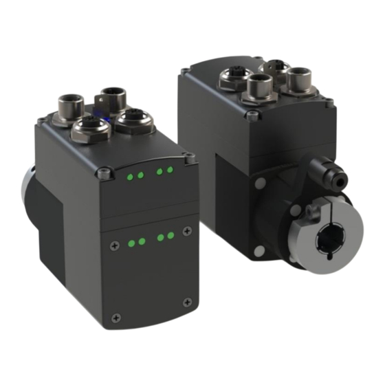
- Page 1 AG25, AG26 Actuator with interface User manual 225/18...
-
Page 2: Table Of Contents
4.1.3.2 Arrangement of the limit switches ..............23 Calibration ......................24 External gear ......................24 Warnings / Errors ..................... 25 Warnings ....................... 25 Errors ........................25 AG25, AG26 Date: 09.07.2018 Art. No. 88094 Mod. status 225/18 Page 2 of 109... - Page 3 8.2.1.23 D-Pos ......................48 8.2.1.24 A-Rot ......................48 8.2.1.25 A-Inch ......................48 8.2.1.26 V-Inch ......................49 8.2.1.27 Pos Window ....................49 8.2.1.28 Gear Ratio Numerator ..................49 AG25, AG26 Date: 09.07.2018 Art. No. 88094 Mod. status 225/18 Page 3 of 109...
- Page 4 8.2.1.68 PCM Deceleration 2 ..................65 8.2.1.69 PCM Deceleration 3 ..................66 8.2.1.70 PCM Deceleration 4 ..................66 8.2.1.71 PCM Deceleration 5 ..................67 8.2.1.72 PCM Deceleration 6 ..................67 AG25, AG26 Date: 09.07.2018 Art. No. 88094 Mod. status 225/18 Page 4 of 109...
- Page 5 8.2.2.12 Sync Manager Rx PDO assign ................83 8.2.2.13 Sync Manager Tx PDO assign ................84 8.2.2.14 SM output parameters ..................84 8.2.2.15 SM input parameters ..................86 AG25, AG26 Date: 09.07.2018 Art. No. 88094 Mod. status 225/18 Page 5 of 109...
- Page 6 Inching 2 Stop Mode ..................94 9.3.4.7 LED Functionality .................... 94 9.3.4.8 Service Interface Baud Rate ................94 9.3.4.9 Configuration ....................94 9.3.5 Controller parameters ..................94 AG25, AG26 Date: 09.07.2018 Art. No. 88094 Mod. status 225/18 Page 6 of 109...
- Page 7 Error Number 7 ....................100 9.3.8.9 Error Number 8 ....................101 9.3.8.10 Error Number 9 ....................101 9.3.8.11 Error Number 10 .................... 101 Commands ......................101 AG25, AG26 Date: 09.07.2018 Art. No. 88094 Mod. status 225/18 Page 7 of 109...
- Page 8 Examples ......................107 9.7.1 Write and read setpoint +500 ................107 9.7.2 Start travel job ....................107 ASCII command structure ..................107 Block diagram ......................109 AG25, AG26 Date: 09.07.2018 Art. No. 88094 Mod. status 225/18 Page 8 of 109...
-
Page 9: General Information
User manual describing the migration of the actuator into an Industrial Ethernet network and its commissioning. These documents can also be found at http://www.siko-global.com/de-de/service-downloads. “EtherCAT® is a registered trademark and patented technology, licensed by Beckhoff Automation GmbH, Deutschland”... -
Page 10: Ethernet Module Statuses
EtherCAT® in the OPERATIONAL state Green, flashing EtherCAT® in the PRE-OPERATIONAL state Green, flashing EtherCAT® in the SAFE-OPERATIONAL state Green, flashing EtherCAT® in the BOOT state Fatal error AG25, AG26 Date: 09.07.2018 Art. No. 88094 Mod. status 225/18 Page 10 of 109... -
Page 11: Drive Status
Operating voltage of the output stage is applied. Red, flashing Actuator is outside the programmed positioning window. Operating voltage of final stage missing Operating voltage of control missing. AG25, AG26 Date: 09.07.2018 Art. No. 88094 Mod. status 225/18 Page 11 of 109... -
Page 12: Operating Elements
This makes it possible to move the actuator without a superordinate control. Key : Inching mode 2 in e direction Key : Inching mode 2 in i direction AG25, AG26 Date: 09.07.2018 Art. No. 88094 Mod. status 225/18... -
Page 13: Dip Switch
With factory settings, the digital output can be actuated via the process data. If a function is assigned to the digital output, it is actuated via register Digital Output Functionalities State (Object 2302h). AG25, AG26 Date: 09.07.2018 Art. No. 88094 Mod. status 225/18 Page 13 of 109... -
Page 14: Examples Of Digital Input Configurations
Digital Input 4 Functionality Digital input 4 Bit 3 Object 2406h, bit 3 = 0 Object 2404h, value = 4 Bit 31 Fig. 3: Examples of digital input configurations AG25, AG26 Date: 09.07.2018 Art. No. 88094 Mod. status 225/18 Page 14 of 109... -
Page 15: Example Of Digital Output Configuration
Digital Outputs Polarity Bit 0 Digital output 1: Object 2301h, value = 2 Object 2303h, Bit 0 = 0 Bit 31 Fig. 4: Example of digital output configuration AG25, AG26 Date: 09.07.2018 Art. No. 88094 Mod. status 225/18 Page 15 of 109... -
Page 16: Functional Description
The status word indicates whether the actual position is within the window defined by parameter Pos Window (Object 260Ah). You can define the behavior of the actuator upon reaching the programmed window via parameter Inpos Mode (Object 2616h). AG25, AG26 Date: 09.07.2018 Art. No. 88094 Mod. status 225/18 Page 16 of 109... -
Page 17: 4.1.1.1.1 Loop Positioning
Case 2 new position is smaller than actual position: The actuator drives beyond the target position by the loop length; afterwards, the set point is approached in positive direction. AG25, AG26 Date: 09.07.2018 Art. No. 88094 Mod. status 225/18... -
Page 18: Inching Mode
The following conditions must be met for enabling the start of inching modes 1 and 2: Supply voltage of the output stage is applied. Operation enabled Drive stands still AG25, AG26 Date: 09.07.2018 Art. No. 88094 Mod. status 225/18... -
Page 19: Inching Mode 2
Fig. 8: Ramp speed mode The following conditions must be met for enabling the start of the rotational speed mode: Supply voltage of the output stage is applied. Operation enabled AG25, AG26 Date: 09.07.2018 Art. No. 88094 Mod. status 225/18... -
Page 20: Position Control Mode
The use of the position control mode requires previous configuration of the digital inputs. The desired travel data set can be selected via inputs PCM input 1 to 3 in binary addressing. Travel data set 0 does not exist. AG25, AG26 Date: 09.07.2018 Art. No. 88094 Mod. -
Page 21: 4.1.1.4.1 Examples Of Configuration Of The Digital Inputs For The Pcm
Example of the parameter set of travel data set no. 3 Parameter Object PCM Position 3 2924h PCM Acceleration 3 2944h PCM Velocity 3 2964h PCM Deceleration 3 2984h AG25, AG26 Date: 09.07.2018 Art. No. 88094 Mod. status 225/18 Page 21 of 109... -
Page 22: Current Limiting
The actuator changes to the error status if the contouring error exceeds the contouring error limit defined by the Contouring Error Limit parameter (Object 2618h): Contouring error. AG25, AG26 Date: 09.07.2018 Art. No. 88094 Mod. status 225/18 Page 22 of 109... -
Page 23: Limit Switch
The limit switches are arranged according to the following pattern independent of the configured sense of rotation: limit switch 2: limit switch 1: Fig. 11: Arrangement of the limit switches AG25, AG26 Date: 09.07.2018 Art. No. 88094 Mod. status 225/18 Page 23 of 109... -
Page 24: Calibration
Input of an odd transmission reduction value is possible according to the following example: Transmission reduction = 3.78 Parameter Gear Ratio Numerator = 378 Parameter Gear Ratio Denominator = 100 AG25, AG26 Date: 09.07.2018 Art. No. 88094 Mod. status 225/18 Page 24 of 109... -
Page 25: Warnings / Errors
The error messages are entered in the error memory in the order of their detection. The last 10 error messages are displayed when the error memory is full. The cause of error can be tracked down with the help of the error codes. AG25, AG26 Date: 09.07.2018 Art. No. 88094 Mod. -
Page 26: Error Codes
Internal error The behavior of the drive when this fault occurs can be set with the parameter configuration, bit 6 (see chapter 8.2.1.99). Table 1: Error codes AG25, AG26 Date: 09.07.2018 Art. No. 88094 Mod. status 225/18 Page 26 of 109... -
Page 27: Ethercat
EEPROM check sum FF14h Ethernet module watchdog FF15h Ethernet module in the ERROR state while travel job is active FF16h Ethernet module in the EXCEPTION state AG25, AG26 Date: 09.07.2018 Art. No. 88094 Mod. status 225/18 Page 27 of 109... -
Page 28: Object Directory (Canopen Over Ethercat®)
Digital Input 4 Functionality 2405h Digital Input Functionalities State 2406h Digital Inputs Polarity 2601h Controller Parameter P 2602h Controller Parameter I 2603h Controller Parameter D 2604h A-Pos 2605h V-Pos AG25, AG26 Date: 09.07.2018 Art. No. 88094 Mod. status 225/18 Page 28 of 109... - Page 29 PCM Acceleration 6 2948h PCM Acceleration 7 2962h PCM Velocity 1 2963h PCM Velocity 2 2964h PCM Velocity 3 2965h PCM Velocity 4 2966h PCM Velocity 5 AG25, AG26 Date: 09.07.2018 Art. No. 88094 Mod. status 225/18 Page 29 of 109...
- Page 30 2B06h Error Number 5 2B07h Error Number 6 2B08h Error Number 7 2B09h Error Number 8 2B0Ah Error Number 9 2B0Bh Error Number 10 2C01h S-Command AG25, AG26 Date: 09.07.2018 Art. No. 88094 Mod. status 225/18 Page 30 of 109...
-
Page 31: Parameter Description Of Manufacturer-Specific Objects
1 … 7 Reserved, always 0 Control Word 8.2.1.2 Object 2002h Description Control word Access rw (component of process data) Data type UNSIGNED16 Default EEPROM Value range UNSIGNED16 AG25, AG26 Date: 09.07.2018 Art. No. 88094 Mod. status 225/18 Page 31 of 109... -
Page 32: Control Word Positioning Mode (Master Slave)
1 = relative positioning Bit 11 … 14 Reserved, always 0 Bit 15 Positive edge calibrates the drive (see chapter 5). Calibration Table 2: Control word of positioning mode AG25, AG26 Date: 09.07.2018 Art. No. 88094 Mod. status 225/18 Page 32 of 109... -
Page 33: 8.2.1.2.2 Flow Chart: Operating Mode: Positioning Mode
SW = 000x x101 01x1 0001 Intermediate stop Continue positioning CW.3 = 0 CW.3 = 1 Intermediate stop active SW = 0000 x101 01x0 0011 Fig. 13: Flowchart positioning mode EtherCAT® AG25, AG26 Date: 09.07.2018 Art. No. 88094 Mod. status 225/18 Page 33 of 109... -
Page 34: 8.2.1.2.3 Control Word: Speed Mode
Positive slope acknowledges an error Acknowledge error Afterwards, the actuator changes to the switch-lock state. Bit 6 … 15 Reserved, always 0 Table 3: Control word of speed mode AG25, AG26 Date: 09.07.2018 Art. No. 88094 Mod. status 225/18 Page 34 of 109... -
Page 35: 8.2.1.2.4 Flow Chart: Speed Mode
CW = 0000 0000 0001 0111 Setpoint enabled Change target value SW = 0000 x101 01xx 0001 Disable setpoint CW.4 = 0 Fig. 14: Flowchart of speed mode EtherCAT® AG25, AG26 Date: 09.07.2018 Art. No. 88094 Mod. status 225/18 Page 35 of 109... -
Page 36: Target Value
State of digital input 3 State of digital input 4 Status Word 8.2.1.5 Object 2102h Description Status word: Access ro (component of process data) Data type UNSIGNED16 Default EEPROM AG25, AG26 Date: 09.07.2018 Art. No. 88094 Mod. status 225/18 Page 36 of 109... -
Page 37: Status Word: Positioning Mode (Slave Master)
The bit is set when the calibration has been performed successfully. If bit 15 is reset in the control parameter, this bit is also reset. Table 4: Status word of positioning mode AG25, AG26 Date: 09.07.2018 Art. No. 88094 Mod. status 225/18... -
Page 38: 8.2.1.5.2 Status Word: Speed Mode
Current limiting 1 = current limiting active Motor current exceeds the value set under parameter Current Limiting (Object 2619h). Table 5: Status word of speed mode AG25, AG26 Date: 09.07.2018 Art. No. 88094 Mod. status 225/18 Page 38 of 109... -
Page 39: Actual Value
Functionality of the system LEDs Access Data type UNSIGNED8 Default EEPROM Value range 0 … 1 Description, see chapter Table 6: Functionality of the system LEDs AG25, AG26 Date: 09.07.2018 Art. No. 88094 Mod. status 225/18 Page 39 of 109... - Page 40 Digital input 4 inactive Red, Error is active flashing LED8 Green Digital input 4 active: Operating voltage of control missing Table 6: Functionality of the system LEDs AG25, AG26 Date: 09.07.2018 Art. No. 88094 Mod. status 225/18 Page 40 of 109...
-
Page 41: Service Interface Baud Rate
The output is switched active in case of fault. Inpos The state of bit Inpos in the status word defines the state of the digital output. Output on The output is switched on permanently. AG25, AG26 Date: 09.07.2018 Art. No. 88094 Mod. status 225/18 Page 41 of 109... -
Page 42: Digital Output Functionalities State
0 … 15 Value of the assigned bits: 0 = positive logics (high-active) 1 = negative logics (low-active) Description Digital output 1 polarity 1 … 15 Not assigned AG25, AG26 Date: 09.07.2018 Art. No. 88094 Mod. status 225/18 Page 42 of 109... -
Page 43: Digital Input 1 Functionality
Object 2402h Description Digital input 2 functionality Access Data type UNSIGNED8 Default EEPROM Value range 0 … 11 Description, see Table 7: Configuration of digital inputs. AG25, AG26 Date: 09.07.2018 Art. No. 88094 Mod. status 225/18 Page 43 of 109... -
Page 44: Digital Input 3 Functionality
Object 2404h Description Digital input 4 functionality Access Data type UNSIGNED8 Default EEPROM Value range 0 … 11 Description, see Table 7: Configuration of digital inputs. AG25, AG26 Date: 09.07.2018 Art. No. 88094 Mod. status 225/18 Page 44 of 109... -
Page 45: Digital Input Functionalities State
Inching mode 1 PCM Start PCM input 1 PCM input 2 PCM input 3 11 … 31 Not assigned Table 8: States of the digital inputs AG25, AG26 Date: 09.07.2018 Art. No. 88094 Mod. status 225/18 Page 45 of 109... -
Page 46: Digital Inputs Polarity
8.2.1.19 This setting applies to all operating modes. Object 2602h Description I gain of controller Access Data type INTEGER16 Default EEPROM Value range 0 … 500 AG25, AG26 Date: 09.07.2018 Art. No. 88094 Mod. status 225/18 Page 46 of 109... -
Page 47: Controller Parameter D
Value range Transmission 66:1 max. 75 rpm Transmission 98:1 max. 50 rpm Transmission 188:1 max. 30 rpm Transmission 368:1 max. 15 rpm AG25, AG26 Date: 09.07.2018 Art. No. 88094 Mod. status 225/18 Page 47 of 109... -
Page 48: D-Pos
1 … 100 % 100 % correspond to: Transmission 66:1 3.04 rps² Transmission 98:1 2.05 rps² Transmission 188:1 1.06 rps² Transmission 368:1 0.54 rps² AG25, AG26 Date: 09.07.2018 Art. No. 88094 Mod. status 225/18 Page 48 of 109... -
Page 49: V-Inch
Object 260Bh Description Numerator transmission ratio Access Data type INTEGER16 Default EEPROM Value range 1 … 10000 AG25, AG26 Date: 09.07.2018 Art. No. 88094 Mod. status 225/18 Page 49 of 109... -
Page 50: Gear Ratio Denominator
Position value = 0 + calibration value + offset value Object 260Eh Description Calibration value Access Data type INTEGER32 Default EEPROM Value range -999999 … 999999 AG25, AG26 Date: 09.07.2018 Art. No. 88094 Mod. status 225/18 Page 50 of 109... -
Page 51: Software Limit 1
(travel range), traveling will only be possible in inching mode in the direction of the travel range. Object 2610h Description Limit 2 Access Data type INTEGER32 Default -19999 EEPROM Value range -9999999 … 9999999 AG25, AG26 Date: 09.07.2018 Art. No. 88094 Mod. status 225/18 Page 51 of 109... -
Page 52: Delta Inch
Description Sense of rotation Access Data type UNSIGNED8 Default EEPROM Value range 0 = i sense of rotation (cw): 1 = e sense of rotation (ccw) AG25, AG26 Date: 09.07.2018 Art. No. 88094 Mod. status 225/18 Page 52 of 109... -
Page 53: Pos Type
2 = loop - Operating Mode 8.2.1.37 Object 2614h Description Operating mode Access Data type UNSIGNED8 Default EEPROM Value range 0 = positioning mode 1 = speed mode AG25, AG26 Date: 09.07.2018 Art. No. 88094 Mod. status 225/18 Page 53 of 109... -
Page 54: Inching 2 Stop Mode
Operating mode: Positioning mode: Value Description Permanent positioning control to setpoint. Position control Off and short circuit of the motor windings Position control Off and drive enable AG25, AG26 Date: 09.07.2018 Art. No. 88094 Mod. status 225/18 Page 54 of 109... -
Page 55: Loop Length
The maximum admissible contouring error is indicated in steps. Object 2618h Description Contouring error limit Access Data type INTEGER16 Default EEPROM Value range 1 … 30000 AG25, AG26 Date: 09.07.2018 Art. No. 88094 Mod. status 225/18 Page 55 of 109... -
Page 56: Current Limiting
Values are given as percentage of parameter V-Inch, Object 2609h. Object 261Ah Description Inching 2 Offset Access Data type UNSIGNED8 Default EEPROM Value range 10 … 100 % AG25, AG26 Date: 09.07.2018 Art. No. 88094 Mod. status 225/18 Page 56 of 109... -
Page 57: Inching 2 Acceleration Type
Position value = 0 + calibration value + offset value Object 261Ch Description Offset value Access Data type INTEGER32 Default EEPROM Value range -999999 … 999999 AG25, AG26 Date: 09.07.2018 Art. No. 88094 Mod. status 225/18 Page 57 of 109... -
Page 58: Pcm Position 1
Spindle pitch > 0 values refer to travel distance in 1/100 mm Object 2924h Description Positioning mode via digital inputs: Position 3 Access Data type INTEGER32 Default EEPROM Value range INTEGER32 AG25, AG26 Date: 09.07.2018 Art. No. 88094 Mod. status 225/18 Page 58 of 109... -
Page 59: Pcm Position 4
Spindle pitch > 0 values refer to travel distance in 1/100 mm Object 2927h Description Positioning mode via digital inputs: Position 6 Access Data type INTEGER32 Default EEPROM Value range INTEGER32 AG25, AG26 Date: 09.07.2018 Art. No. 88094 Mod. status 225/18 Page 59 of 109... -
Page 60: Pcm Position 7
1 … 100 % 100 % correspond to: Transmission 66:1 3.04 rps² Transmission 98:1 2.05 rps² Transmission 188:1 1.06 rps² Transmission 368:1 0.54 rps² AG25, AG26 Date: 09.07.2018 Art. No. 88094 Mod. status 225/18 Page 60 of 109... -
Page 61: Pcm Acceleration 3
1 … 100 % 100 % correspond to: Transmission 66:1 3.04 rps² Transmission 98:1 2.05 rps² Transmission 188:1 1.06 rps² Transmission 368:1 0.54 rps² AG25, AG26 Date: 09.07.2018 Art. No. 88094 Mod. status 225/18 Page 61 of 109... -
Page 62: Pcm Acceleration 6
Value range Transmission 66:1 max. 75 rpm Transmission 98:1 max. 50 rpm Transmission 188:1 max. 30 rpm Transmission 368:1 max. 15 rpm AG25, AG26 Date: 09.07.2018 Art. No. 88094 Mod. status 225/18 Page 62 of 109... -
Page 63: Pcm Velocity 2
Value range Transmission 66:1 max. 75 rpm Transmission 98:1 max. 50 rpm Transmission 188:1 max. 30 rpm Transmission 368:1 max. 15 rpm AG25, AG26 Date: 09.07.2018 Art. No. 88094 Mod. status 225/18 Page 63 of 109... -
Page 64: Pcm Velocity 5
Value range Transmission 66:1 max. 75 rpm Transmission 98:1 max. 50 rpm Transmission 188:1 max. 30 rpm Transmission 368:1 max. 15 rpm AG25, AG26 Date: 09.07.2018 Art. No. 88094 Mod. status 225/18 Page 64 of 109... -
Page 65: Pcm Deceleration 1
101 % = the delay is determined by the PCM Acceleration 2 parameter. 100 % correspond to: Transmission 66:1 3.04 rps² Transmission 98:1 2.05 rps² Transmission 188:1 1.06 rps² Transmission 368:1 0.54 rps² AG25, AG26 Date: 09.07.2018 Art. No. 88094 Mod. status 225/18 Page 65 of 109... -
Page 66: Pcm Deceleration 3
101 % = the delay is determined by the PCM Acceleration 4 parameter. 100 % correspond to: Transmission 66:1 3.04 rps² Transmission 98:1 2.05 rps² Transmission 188:1 1.06 rps² Transmission 368:1 0.54 rps² AG25, AG26 Date: 09.07.2018 Art. No. 88094 Mod. status 225/18 Page 66 of 109... -
Page 67: Pcm Deceleration 5
101 % = the delay is determined by the PCM Acceleration 6 parameter. 100 % correspond to: Transmission 66:1 3.04 rps² Transmission 98:1 2.05 rps² Transmission 188:1 1.06 rps² Transmission 368:1 0.54 rps² AG25, AG26 Date: 09.07.2018 Art. No. 88094 Mod. status 225/18 Page 67 of 109... -
Page 68: Pcm Deceleration 7
Access Data type INTEGER16 Default EEPROM Voltage of Control 8.2.1.75 Object 2A02h Description Operating voltage of control Unit 1/10 V Access Data type INTEGER16 Default EEPROM AG25, AG26 Date: 09.07.2018 Art. No. 88094 Mod. status 225/18 Page 68 of 109... -
Page 69: Voltage Of Output Stage
Actual Position 8.2.1.79 Object 2A06h Description Actual position Unit Spindle pitch = 0: Steps Spindle pitch > 0: 1/100 mm Access Data type INTEGER32 Default EEPROM AG25, AG26 Date: 09.07.2018 Art. No. 88094 Mod. status 225/18 Page 69 of 109... -
Page 70: Actual Rotational Speed
Unit DDMMYYYY Access Data type INTEGER32 Default EEPROM SW Motor Controller 8.2.1.83 Object 2A0Ah Description Motor Controller software version Unit Access Data type INTEGER32 Default EEPROM AG25, AG26 Date: 09.07.2018 Art. No. 88094 Mod. status 225/18 Page 70 of 109... -
Page 71: Gear Reduction
0010 1001 0100 1000 hex: Object 2A0Ch Description System status word Unit Access Data type UNSIGNED16 Default EEPROM Description of the bits, see Table 9: System status word AG25, AG26 Date: 09.07.2018 Art. No. 88094 Mod. status 225/18 Page 71 of 109... - Page 72 Ready for travel: Actuator not in error state No active positioning Supply voltage of the output stage is applied Actual position within limits (only positioning mode) AG25, AG26 Date: 09.07.2018 Art. No. 88094 Mod. status 225/18 Page 72 of 109...
-
Page 73: Encoder Resolution
Data type INTEGER16 Default EEPROM Device ID 8.2.1.87 Object 2A0Eh Description Device identification Unit Access Data type UNSIGNED8 Default EEPROM 1 = AG25 2 = AG26 AG25, AG26 Date: 09.07.2018 Art. No. 88094 Mod. status 225/18 Page 73 of 109... -
Page 74: Number Of Errors
Description Error 2 Unit Access Data type UNSIGNED8 Default EEPROM Error Number 3 8.2.1.91 Object 2B04h Description Error 3 Unit Access Data type UNSIGNED8 Default EEPROM AG25, AG26 Date: 09.07.2018 Art. No. 88094 Mod. status 225/18 Page 74 of 109... -
Page 75: Error Number 4
Description Error 6 Unit Access Data type UNSIGNED8 Default EEPROM Error Number 7 8.2.1.95 Object 2B08h Description Error 7 Unit Access Data type UNSIGNED8 Default EEPROM AG25, AG26 Date: 09.07.2018 Art. No. 88094 Mod. status 225/18 Page 75 of 109... -
Page 76: Error Number 8
Description Error 9 Unit Access Data type UNSIGNED8 Default EEPROM Error Number 10 8.2.1.98 Object 2B0Bh Description Error 10 Unit Access Data type UNSIGNED8 Default EEPROM AG25, AG26 Date: 09.07.2018 Art. No. 88094 Mod. status 225/18 Page 76 of 109... -
Page 77: Configuration
Data type UNSIGNED8 Default EEPROM Value Description All parameters to default Only standard parameters to default Controller parameters to default Reset error Calibrate Delete error memory AG25, AG26 Date: 09.07.2018 Art. No. 88094 Mod. status 225/18 Page 77 of 109... -
Page 78: Standard Objects Parameter Description
Object 1003h Sub-index Description Number of errors Access Data type UNSIGNED8 Default Object 1003h Sub-index 01h - 05h Description Error 1-5 Access Data type UNSIGNED32 Default AG25, AG26 Date: 09.07.2018 Art. No. 88094 Mod. status 225/18 Page 78 of 109... -
Page 79: Manufacturer Device Name
Software version Access Data type VISIBLE_STRING Default Current software version “SW_1.04” Restore default parameters 8.2.2.7 Object 1011h Sub-index Description Largest sub-index supported Access Data type UNSIGNED8 Default AG25, AG26 Date: 09.07.2018 Art. No. 88094 Mod. status 225/18 Page 79 of 109... -
Page 80: Identity Object
0000 0195h (SIKO GmbH) Object 1018h Sub-index Description Product code Access Data type UNSIGNED32 Default 0001 0104h ( AG25-66 ) 0001 0100h ( AG25-98 ) 0001 0202h ( AG26-188 ) 0001 0203h ( AG26-368) Object 1018h Sub-index Description Revision number Access... -
Page 81: Receive Pdo Mapping
Sub-index Description Mapped object 002 Access Data type UNSIGNED32 Default 2003 0020h Object 1600h Sub-index Description Mapped object 003 Access Data type UNSIGNED32 Default 2001 0008h AG25, AG26 Date: 09.07.2018 Art. No. 88094 Mod. status 225/18 Page 81 of 109... -
Page 82: Transmit Pdo Mapping
Data type UNSIGNED32 Default 2101 0008h Sync Manager Communication Type 8.2.2.11 Object 1C00h Sub-index Description Number of Sync manager channels used Access Data type UNSIGNED8 Default AG25, AG26 Date: 09.07.2018 Art. No. 88094 Mod. status 225/18 Page 82 of 109... -
Page 83: Sync Manager Rx Pdo Assign
Access Data type UNSIGNED8 Default 4 (Tx PDO) Sync Manager Rx PDO assign 8.2.2.12 Object 1C12h Sub-index Description Number of entries Access Data type UNSIGNED8 Default AG25, AG26 Date: 09.07.2018 Art. No. 88094 Mod. status 225/18 Page 83 of 109... -
Page 84: Sync Manager Tx Pdo Assign
Object 1C32h Sub-index Description Largest sub-index supported Access Data type UNSIGNED8 Default Object 1C32h Sub-index Description Sync Mode Access Data type UNSIGNED16 Default 00h (Free Run) AG25, AG26 Date: 09.07.2018 Art. No. 88094 Mod. status 225/18 Page 84 of 109... - Page 85 Access Data type UNSIGNED32 Default 0001 86A0h (100000 ns) Object 1C32h Sub-index Description Calc to Copy Time Access Data type UNSIGNED32 Default 0000 01F5h (500 ns) AG25, AG26 Date: 09.07.2018 Art. No. 88094 Mod. status 225/18 Page 85 of 109...
-
Page 86: Sm Input Parameters
Description Sync Mode Access Data type UNSIGNED16 Default 00h (Free Run) Object 1C33h Sub-index Description Cycle time Access Data type UNSIGNED32 Default 001E 8480h (2000000 ns) AG25, AG26 Date: 09.07.2018 Art. No. 88094 Mod. status 225/18 Page 86 of 109... - Page 87 Calc to Copy Time Access Data type UNSIGNED32 Default 0000 01F5h (500 ns) Object 1C33h Sub-index Description Cycle Time Too Small Access Data type UNSIGNED16 Default AG25, AG26 Date: 09.07.2018 Art. No. 88094 Mod. status 225/18 Page 87 of 109...
-
Page 88: Service Protocol
Length and format of the response are defined unchangeably for every ASCII command. Overview of parameters Chapter starting with page Positioning Actuator Limiting values Options Controller parameters Device information Digital input/output AG25, AG26 Date: 09.07.2018 Art. No. 88094 Mod. status 225/18 Page 88 of 109... -
Page 89: Parameters
8.2.1.80 Actual Rotational Speed Calibration Value 9.3.1.4 Read command see chapter 9.8 ASCII command structure Write command F3±xxxxxxx Description see chapter 8.2.1.31 Calibration Value AG25, AG26 Date: 09.07.2018 Art. No. 88094 Mod. status 225/18 Page 89 of 109... -
Page 90: Loop Length
Reading of the sense of rotation is via the flag register (see chapter 9.3.6.6: Flag Register). x = 0: i sense of rotation x = 1: e sense of rotation AG25, AG26 Date: 09.07.2018 Art. No. 88094 Mod. status 225/18 Page 90 of 109... -
Page 91: Actuator
Write command H05xxxxx Description see chapter 8.2.1.24 A-Rot A-Inch 9.3.2.5 Read command see chapter 9.8 ASCII command structure Write command H07xxxxx Description see chapter 8.2.1.25 A-Inch AG25, AG26 Date: 09.07.2018 Art. No. 88094 Mod. status 225/18 Page 91 of 109... -
Page 92: V-Inch
8.2.1.33 Software Limit 2 Current Limiting 9.3.3.3 Read command see chapter 9.8 ASCII command structure Write command H24xxxxx Description see chapter 8.2.1.42 Current Limiting AG25, AG26 Date: 09.07.2018 Art. No. 88094 Mod. status 225/18 Page 92 of 109... -
Page 93: Contouring Error Limit
8.2.1.44 Inching 2 Acceleration Type Inching 2 Offset 9.3.4.5 Read command see chapter 9.8 ASCII command structure Write command H27xxxxx Description see chapter 8.2.1.43 Inching 2 Offset AG25, AG26 Date: 09.07.2018 Art. No. 88094 Mod. status 225/18 Page 93 of 109... -
Page 94: Controller Parameter P
8.2.1.18 Controller Parameter P Controller Parameter I 9.3.5.2 Read command see chapter 9.8 ASCII command structure Write command H01xxxxx Description see chapter 8.2.1.19 Controller Parameter I AG25, AG26 Date: 09.07.2018 Art. No. 88094 Mod. status 225/18 Page 94 of 109... -
Page 95: Controller Parameter D
8.2.1.76 Voltage of Output Stage Voltage of Battery 9.3.6.5 Read command see chapter 9.8 ASCII command structure Write command read-only Description see chapter 8.2.1.77 Voltage of Battery AG25, AG26 Date: 09.07.2018 Art. No. 88094 Mod. status 225/18 Page 95 of 109... -
Page 96: Flag Register
8.2.1.85 System Status Word Device Type 9.3.6.8 Read command see chapter 9.8 ASCII command structure Write command read-only Description Response format: "AG25 >" Gear Reduction 9.3.6.9 Read command see chapter 9.8 ASCII command structure Write command read-only Description Response format: "98... -
Page 97: Network Type
Digital input/output 9.3.7 Digital Input 1 Functionality 9.3.7.1 Read command see chapter 9.8 ASCII command structure Write command H49xxxxx Description see chapter 8.2.1.12 Digital Input 1 Functionality AG25, AG26 Date: 09.07.2018 Art. No. 88094 Mod. status 225/18 Page 97 of 109... -
Page 98: Digital Input 2 Functionality
8.2.1.17 Digital Inputs Polarity Digital Inputs State 9.3.7.7 Read command see chapter 9.8 ASCII command structure Write command read-only Description see chapter 8.2.1.4 Digital Inputs State AG25, AG26 Date: 09.07.2018 Art. No. 88094 Mod. status 225/18 Page 98 of 109... -
Page 99: Digital Output 1 Functionality
8.2.1.88 Number of Errors Error Number 1 9.3.8.2 Read command see chapter 9.8 ASCII command structure Write command read-only Description see chapter 8.2.1.89 Error Number 1 AG25, AG26 Date: 09.07.2018 Art. No. 88094 Mod. status 225/18 Page 99 of 109... -
Page 100: Error Number 2
8.2.1.94 Error Number 6 Error Number 7 9.3.8.8 Read command see chapter 9.8 ASCII command structure Write command read-only Description see chapter 8.2.1.95 Error Number 7 AG25, AG26 Date: 09.07.2018 Art. No. 88094 Mod. status 225/18 Page 100 of 109... -
Page 101: Error Number 8
9.8 ASCII command structure Description Drive travels in positive direction as long as the "," ASCII character is permanently sent (only in positioning mode). AG25, AG26 Date: 09.07.2018 Art. No. 88094 Mod. status 225/18 Page 101 of 109... -
Page 102: Start Inching Mode 2 Negative Travel Direction
9.8 ASCII command structure Description Motor is enabled Factory setting: all parameters 9.4.9 Command S11100 see chapter 9.8 ASCII command structure Description Reset all parameters to factory settings AG25, AG26 Date: 09.07.2018 Art. No. 88094 Mod. status 225/18 Page 102 of 109... -
Page 103: Factory Setting: Standard Parameter
9.8 ASCII command structure Description Deleting of the error memory Software Reset 9.4.15 Command see chapter 9.8 ASCII command structure Description Execute software reset AG25, AG26 Date: 09.07.2018 Art. No. 88094 Mod. status 225/18 Page 103 of 109... -
Page 104: Flow Charts
Intermediate stop continue positioning ‘N‘ or ‘O‘ command ‘M‘ command Intermediate stop active SW = x10x 00x0 0000 0000 Fig. 16: Flowchart of positioning mode service protocol AG25, AG26 Date: 09.07.2018 Art. No. 88094 Mod. status 225/18 Page 104 of 109... -
Page 105: Flow Chart: Speed Mode
Target speed enabled ‘F0‘ command SW = 01xx x000 000x x000 Stop travel job ‘N‘ or ‘O‘ command Fig. 17: Flow chart speed mode service protocol AG25, AG26 Date: 09.07.2018 Art. No. 88094 Mod. status 225/18 Page 105 of 109... -
Page 106: Error Number Encoding
Fault Active EEPROM write access Actual or target value < lower area limit Actual or target value > upper area limit Operating voltage of control missing AG25, AG26 Date: 09.07.2018 Art. No. 88094 Mod. status 225/18 Page 106 of 109... -
Page 107: Examples
Error memory yy = address hh = hexadecimal value write > Software Reset write > Type of positioning x = decimal value write > Start travel job AG25, AG26 Date: 09.07.2018 Art. No. 88094 Mod. status 225/18 Page 107 of 109... - Page 108 ±xxxxxxx> x Position value ±xxxxxxx decimal value , (2C write Start inching mode 2 positive travel direction . (2E write Start inching mode 2 negative travel direction AG25, AG26 Date: 09.07.2018 Art. No. 88094 Mod. status 225/18 Page 108 of 109...
-
Page 109: Block Diagram
Ethernet Ethernet module Digital I Control reverse Power polarity pack Control protection reverse Motor Encoder Output stage polarity Output protection stage Battery Fig. 18: Block diagram AG25, AG26 Date: 09.07.2018 Art. No. 88094 Mod. status 225/18 Page 109 of 109...
Need help?
Do you have a question about the AG25 and is the answer not in the manual?
Questions and answers