Table of Contents
Advertisement
Quick Links
Advertisement
Table of Contents

Related Manuals for EDAN M3A


Summary of Contents for EDAN M3A
-
Page 2: About This Manual
This manual will help you understand the operation and maintenance of the product better. It is reminded that the product shall be used strictly complying with this manual. User’s operation failing to comply with this manual may result in malfunction or accident for which EDAN INSTRUMENTS, INC. (hereinafter called EDAN) can not be held liable. - Page 3 Terms Used in this Manual This guide is designed to give key concepts on safety precautions. WARNING A WARNING label advises against certain actions or situations that could result in personal injury or death. CAUTION A CAUTION label advises against actions or situations that could damage equipment, produce inaccurate data, or invalidate a procedure.
-
Page 4: Table Of Contents
Table of Contents Chapter 1 Intended Use and Safety Guidance ................1 1.1 Intended Use...........................1 1.2 Safety Guidance ........................1 1.2.1 Environment........................1 1.2.2 Power Source Requirements ..................1 1.2.3 Grounding the Monitor ....................1 1.2.4 Equipotential Grounding.....................2 1.2.5 Condensation.......................2 1.2.6 Safety Precautions.......................2 1.2.7 Explanation of Symbols on the Monitor ..............5 Chapter 2 Installation of Monitor ....................8 2.1 Opening the Package and Checking..................8 2.2 Connecting the Power Cable....................8... -
Page 5: Table Of Contents
4.10 Standby Mode ........................33 Chapter 5 Alarm..........................35 5.1 Alarm Modes........................35 5.1.1 Alarm Level.......................35 5.1.2 Alarm Modes......................35 5.1.3 Alarm Setup.......................37 5.2 Alarm Cause .........................38 5.3 Silence ..........................38 5.4 Parameter Alarm........................39 5.5 When an Alarm Occurs ......................39 5.6 Testing Alarms........................39 Chapter 6 Trend ..........................40 6.1 Trend List ..........................40 6.2 Trend Graph .........................41 Chapter 7 Recording........................43... -
Page 6: Table Of Contents
10.3 NIBP Setup Menu ......................61 10.3.1 NIBP Setup......................61 10.3.2 NIBP Alarm Setup....................61 10.4 NIBP Alarm Message and Prompt Message ..............63 10.5 Maintenance and Cleaning....................66 Chapter 11 TEMP Monitoring (Optional) ..................68 11.1 TEMP Monitoring with T2 Module ...................68 11.1.1 Introduction ......................68 11.1.2 Measuring Procedure....................69 11.1.3 TEMP Setup Menu ....................70 11.1.4 Alarm Message......................71... - Page 7 A2.3 Electromagnetic Immunity - For EQUIPMENT and SYSTEMS that are not LIFE-SUPPORTING......................93 A2.4 Recommended Separation Distances ................94...
-
Page 8: Chapter 1 Intended Use And Safety Guidance
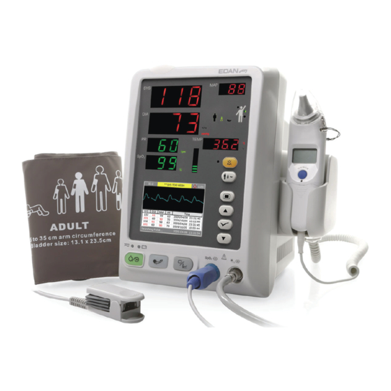
Intended Use and Safety Guidance Chapter 1 Intended Use and Safety Guidance 1.1 Intended Use The M3A Vital Signs Monitor (hereinafter called monitor) is intended to be used for non-invasive continuous monitoring of SpO (oxygen saturation of arterial blood), NIBP (non-invasive blood pressure) and TEMP (temperature). -
Page 9: Equipotential Grounding
M3A Vital Signs Monitor User Manual Intended Use and Safety Guidance 1.2.4 Equipotential Grounding Protection class 1 instruments are already included in the protective grounding (protective earth) system of the room by way of grounding contacts in the power plug. For internal examinations on the heart or the brain, the Monitor must have a separate connection to the equipotential grounding system. - Page 10 Keep it away from the monitor. 15 Do not use a battery with serious scar or deformation. 16 Only patient cable and other accessories supplied by EDAN can be used. Or else, the performance and electric shock protection can not be guaranteed, and the patient may be injured.
- Page 11 M3A Vital Signs Monitor User Manual Intended Use and Safety Guidance WARNING 21 The simultaneous use of cardiac pacemaker and other patient-connected equipment may cause safety hazard. 22 Please disinfect timely to prevent cross infection between patients. 23 This monitor is not a device for treatment purposes.
-
Page 12: Explanation Of Symbols On The Monitor
M3A Vital Signs Monitor User Manual Intended Use and Safety Guidance CAUTION 9 Before use, the equipment, patient cable and sensor should be checked. Replacement should be taken if there is any evident defectiveness or aging symptom which may impair the safety or performance. - Page 13 M3A Vital Signs Monitor User Manual Intended Use and Safety Guidance This symbol indicates that instrument IEC/EN60601-1 Type BF equipment. The unit displaying this symbol contains an F-Type isolated (floating) patient applied part providing a high degree of protection against shock.
- Page 14 M3A Vital Signs Monitor User Manual Intended Use and Safety Guidance Part Number Recycle The symbol indicates that the device should be sent to the special agencies according to local regulations for separate collection after its useful life. Federal law (U.S.) restricts this device to sale by or on the Rx only order of a physician.
-
Page 15: Chapter 2 Installation Of Monitor
M3A Vital Signs Monitor User Manual Installation of Monitor Chapter 2 Installation of Monitor NOTE: To ensure that the monitor works properly, please read Chapter 1 Intended Use and Safety Guidance, and follow the steps before using the monitor. 2.1 Opening the Package and Checking Visually examine the package prior to unpacking. -
Page 16: Connecting Sensor To Patient
M3A Vital Signs Monitor User Manual Installation of Monitor NOTE: 1 During POST, make sure all the seven segments are bright, which indicates the seven segments function well. 2 Check all the functions of the monitor and make sure that the monitor is in good condition. -
Page 17: Chapter 3 Introduction
M3A Vital Signs Monitor User Manual Introduction Chapter 3 Introduction 3.1 General Information The monitor integrates the function of parameter measurement modules, display and output to compose a compact, portable device. Its built-in replaceable battery provides convenience for patient movement. -
Page 18: Screen Display
M3A Vital Signs Monitor User Manual Introduction M3A Vital Signs Monitor can monitor: Oxygen saturation of arterial blood (SpO Pulse Rate (PR); PLETH (Plethysmogram); NIBP: Systolic Pressure (SYS); Diastolic Pressure (DIA); Mean Pressure (MAP); Pulse Rate (PR). TEMP: Temperature. The monitor provides extensive functions such as visual and audible alarms, storage for data, /NIBP/TEMP measurements review, nurse call and so on. - Page 19 M3A Vital Signs Monitor User Manual Introduction Figure 3-2 Main display The NIBP multi-group Review and SpO waveform area is displayed as follows: Figure 3-3 NIBP Multi-group Review Change the display on the screen to Trend list as follows: - 12 -...
- Page 20 M3A Vital Signs Monitor User Manual Introduction Figure 3-4 Display trend list Change the display on the screen to Trend graph as follows: Figure 3-5 Display SpO trend graph The icons on the interface and their meanings are as follows:...
- Page 21 M3A Vital Signs Monitor User Manual Introduction Indicates an error occurs Note Warning Password protection Patient type: ADU (adult) Patient type: PED (pediatric) Patient type: NEO (neonatal) Measuring oral TEMP For device with TEMP Measuring axillary module only. TEMP Measuring...
- Page 22 M3A Vital Signs Monitor User Manual Introduction NIBP: SYS, DIA, MAP (Unit: mmHg or kPa). Pulse Rate (Pulse Rate, Unit: BPM) TEMP: Temperature (Unit: The PR signal from SpO measuring takes priority to be displayed. Waveform/Trend List ( It can display SpO waveform, NIBP multi-group review, trend list or trend graph.
-
Page 23: Optional Displays
M3A Vital Signs Monitor User Manual Introduction 3.2.2 Optional Displays only measuring mode Figure 3-6 Display in SpO only mode - 16 -... - Page 24 M3A Vital Signs Monitor User Manual Introduction NIBP only measuring mode In NIBP only measuring mode, the PR from NIBP measurement is also displayed on screen. Figure 3-7 Display in NIBP only mode - 17 -...
-
Page 25: Button Functions
M3A Vital Signs Monitor User Manual Introduction 3.3 Button Functions Figure 3-8 Buttons All the operations to the monitor can be finished by several buttons. When the monitor is off, press this button to turn it on. ON/OFF When the monitor is on, press this button and hold for 2s to turn off the monitor;... - Page 26 M3A Vital Signs Monitor User Manual Introduction TREND/WAVEFORM Press this button to switch among waveform display, trend list and trend graph display. Press this button for less than 2s to silence the audible alarm for a period; the icon displays in the information area and the indicator beside the button flashes.
-
Page 27: Interfaces
Sensor port on the front panel Figure 3-9 Sensor Connectors Connectors for cables and sensors are as shown in Figure 3-9. 1. SpO sensor connector 2. NIBP cuff connector WARNING Only connect the device to EDAN supplied or recommended accessories. - 20 -... - Page 28 M3A Vital Signs Monitor User Manual Introduction Rear Panel Figure 3-10 Rear Panel Sockets on the rear panel are shown in the above figure: Equipotential grounding terminal for connecting to the hospital’s grounding system. Power supply socket: 100V–240V ~, 50Hz/60Hz.
-
Page 29: Built-In Rechargeable Battery
M3A Vital Signs Monitor User Manual Introduction Bottom panel There are battery compartment and fuse box on the bottom panel. Battery compartment cover Fuse box Figure 3-11 Bottom panel 3.5 Built-in Rechargeable Battery The monitor is equipped with a built-in rechargeable battery. When switching on AC power supply, the battery will be recharged automatically until full electric energy. - Page 30 M3A Vital Signs Monitor User Manual Introduction Replace Battery In monitoring or communication state, the battery status indicator will flash when the battery is low or empty. When the lifespan of battery is over, foul odor or leakage is detected, please contact the manufacturer or local distributor for replacement of battery.
-
Page 31: Chapter 4 System Menu
M3A Vital Signs Monitor User Manual System Menu Chapter 4 System Menu The monitor features in flexible configurations. You can configure various aspects of the monitor, including the parameters to be monitored, audio signal volume, and output content. Press the MENU button on the front panel to open Main Menu. You can perform the following operations in this menu. -
Page 32: Temp Setup
M3A Vital Signs Monitor User Manual System Menu 4.3 SpO Setup Please refer to 9.5.1 SpO Setup for more information. 4.4 TEMP Setup Please refer to 11.1.3.1 or 11.2.3 TEMP Setup for more information. 4.5 Alarm Setup Select Alarm Setup in Main Menu to open submenu as shown below, in which the user may turn on or off alarm or set the upper alarm limit or lower alarm limit. -
Page 33: Recorder
M3A Vital Signs Monitor User Manual System Menu Start Data Transmission: select this item to start transmitting data from monitor to data management software. 4.7 Recorder Select Recorder in Main Menu to open the following menu. Figure 4-5 Recorder Record Realtime Data: Select it to output the real time data from the monitor. -
Page 34: General Alarm Setup
M3A Vital Signs Monitor User Manual System Menu Figure 4-7 General Setup Key Volume: set key volume to level 0 ~ 5. LCD Brightness: set LCD brightness to level 1 ~ 5. Standby Mode: set to ON or OFF. If you set this item to ON, when pressing ON/OFF button for less than 1s, the monitor will enter Standby Mode. -
Page 35: Default Configuration
Save as User Default Config: save the current setup as the user default configuration; 4.9 Maintenance Select Maintenance in Main Menu to open the following menu. Factory Maintenance is only available for the service engineers of EDAN or representatives authorized by EDAN. Figure 4-11 Maintenance - 28 -... - Page 36 M3A Vital Signs Monitor User Manual System Menu User Maintenance Input the user password 9 9 8 1 in the Enter Password box and press Confirm: Figure 4-12 Enter the Password User Maintenance menu will pop up, in which you can set the following items.
- Page 37 M3A Vital Signs Monitor User Manual System Menu NIBP Memory You can set this item to ON or OFF. If the item is ON, the monitor will automatically memorize the initial measurements of the patient when measuring his or her blood pressure.
- Page 38 M3A Vital Signs Monitor User Manual System Menu Leak Test This item is used for air leakage test. Press this item to start the air leakage test. Then the item will change into Stop Leakage Test. If it is picked again, the system will stop air leakage test.
- Page 39 M3A Vital Signs Monitor User Manual System Menu Figure 4-17 SpO Setup Sensitivity The SpO reading is the average of data collected within a specific time. You can set Sensitivity to Low, Medium or High via the menu. The higher the sensitivity is, the quicker the pulse oximeter responds to the changes in the patient’s oxygen saturation level.
-
Page 40: Standby Mode
Server Port: Set the server port. Exit: Exit the menu. Factory Maintenance Factory maintenance function is only available for the service engineers of EDAN or representative authorized by EDAN. Version Select Main Menu > Maintenance > About to check the version of the modules. - Page 41 M3A Vital Signs Monitor User Manual System Menu Figure 4-21 2. If the battery is low, press the ON/OFF button for less than 2 seconds, the following dialog box displays: Figure 4-22 Quitting Standby Mode In Standby Mode, press any button on the front panel to quit standby mode.
-
Page 42: Chapter 5 Alarm
M3A Vital Signs Monitor User Manual Alarm Chapter 5 Alarm This chapter gives general information about the alarm and measures to be taken accordingly. Alarm setup and prompt messages are provided in respective parameter setup sections. WARNING A potential hazard can exist if different alarm presets are used for the same or similar equipment in any single area, e.g. - Page 43 M3A Vital Signs Monitor User Manual Alarm NOTE: The concrete presentation of each alarm prompt is related to the alarm level. Screen display When the measured parameter exceeds its alarm limits and triggers a physiological alarm, the alarm prompt will display on the screen of the monitor.
-
Page 44: Alarm Setup
M3A Vital Signs Monitor User Manual Alarm WARNING Do not rely exclusively on the audible alarm system for patient monitoring. Adjustment of alarm volume to a low level or off during patient monitoring may result in patient danger. Remember that the most reliable method of patient monitoring combines close personal surveillance with correct operation of monitoring equipment. -
Page 45: Alarm Cause
M3A Vital Signs Monitor User Manual Alarm 5.2 Alarm Cause Alarm occurs when: 1. Physiological alarm is evoked; 2. Alarm for error of the system (technical alarm) is evoked; 3. General alert occurs. A. Conditions that activate the parameter alarms: The measurement value exceeds the alarm limit and the alarm is set to ON. -
Page 46: Parameter Alarm
M3A Vital Signs Monitor User Manual Alarm 5.4 Parameter Alarm WARNING Prior to monitoring, make sure that the alarm limit settings are appropriate for your patient. Setting alarm limits to extreme values may cause the alarm system to become ineffective. -
Page 47: Chapter 6 Trend
M3A Vital Signs Monitor User Manual Trend Chapter 6 Trend The monitor provides 100-hour trend data of all parameters (SYS, MAP, DIA, PR, SpO , TEMP), 2-hour trend graph of NIBP/SpO /PR/TEMP, storage data of 12, 000 NIBP measurement results and 200 Patient IDs. -
Page 48: Trend Graph
M3A Vital Signs Monitor User Manual Trend Select one data file and press the OK button, the following menu and deleting process are displayed: Figure 6-3 Delete Data in Trend List When deleting data, the process bar is diaplayed: Figure 6-4 Deleting process 6.2 Trend Graph... - Page 49 M3A Vital Signs Monitor User Manual Trend Figure 6-6 NIBP Trend Graph You can set the items below the trend graph. Item: you can set the display parameter to NIBP, SpO or PR. Y: it stands for the ordinate which indicates the displayed data range.
-
Page 50: Chapter 7 Recording
M3A Vital Signs Monitor User Manual Recording Chapter 7 Recording 7.1 Recorder A thermal dot matrix recorder is used for the monitor. It supports the printout of real time data, trend graph and trend table. 7.1.1 Performance of the Recorder... -
Page 51: Outputing The Monitoring Data
M3A Vital Signs Monitor User Manual Recording Cut the paper from the feeding edge. Open the recorder door. Reload the paper and close the recorder door. 7.2 Outputing the Monitoring Data By selecting the items on Main Menu > Recorder (Figure 7-1), you can output the real time data, trend graph and trend table. -
Page 52: Chapter 8 Maintenance And Cleaning
If you find any damage on the monitor, stop using the monitor on patient, and contact the biomedical engineer of the hospital or EDAN immediately. The overall check of the monitor, including the safety check, should be performed only by qualified personnel once every 24 months, and each time after fixing up. - Page 53 M3A Vital Signs Monitor User Manual Maintenance and Cleaning CAUTION Please pay special attention to the following items: 1 Most cleaning agents must be diluted before use. Follow the manufacturer's directions carefully to avoid damaging the monitor. 2 Do not use the grinding material, such as steel, wool etc.
-
Page 54: Sterilization
M3A Vital Signs Monitor User Manual Maintenance and Cleaning 8.3 Sterilization To avoid extended damage to the equipment, sterilization is only recommended when stipulated as necessary in the Hospital Maintenance Schedule. Sterilization facilities should be cleaned first. Recommended sterilization material: Ethylate, and Acetaldehyde. -
Page 55: Replacement Of Fuse
M3A Vital Signs Monitor User Manual Maintenance and Cleaning 8.5 Replacement of Fuse Unscrew the fuse cap anticlockwise, replace the fuse (protector tube) and screw down the fuse cap clockwise. Fuse size: 5×20, Rated value: T 1.6 AL /250 V. - Page 56 M3A Vital Signs Monitor User Manual Monitoring (Optional) Chapter 9 SpO Monitoring (Optional) 9.1 What is SpO Monitoring The monitor uses oximetry to measure functional oxygen saturation in the blood. SpO Plethysmogram measurement is employed to determine the functional oxygen saturation of hemoglobin in the arterial blood.
- Page 57 M3A Vital Signs Monitor User Manual Monitoring (Optional) 9.2 Precautions During SpO /PR Monitoring WARNING Verify sensor cable fault detection before beginning of monitoring phase. Unplug the sensor cable from the socket, the screen will display the error message SpO SENSOR OFF and the audible alarm is activated.
-
Page 58: Monitoring Procedure
M3A Vital Signs Monitor User Manual Monitoring (Optional) 9.3 Monitoring Procedure plethysmogram measurement 1. Connect the SpO sensor and extension cable to the SpO sensor port of monitor. 2. Switch on the monitor. 3. Enter Patient Setup menu to set Patient Type as required. -
Page 59: Alarm Setup Menu
M3A Vital Signs Monitor User Manual Monitoring (Optional) 9.5 SpO Setup Menu 9.5.1 SpO Setup Click on SpO Setup in Main Menu to open the following menu: Figure 9-2 SpO Setup Pulse Volume: Set it to level 0 ~ 5. -
Page 60: Alarm Description
M3A Vital Signs Monitor User Manual Monitoring (Optional) WARNING In order to avoid endangering the patient’s life, the user should use this function cautiously. The range of SpO alarm limit is: 0 ~ 100. Default SpO alarm limits: Max. Upper Limit Min. - Page 61 M3A Vital Signs Monitor User Manual Monitoring (Optional) Message Cause Alarm Level Sphygmic signal from the measured position is too NO PULSE weak; the monitor does not detect any sphygmic High signal. Technical alarms: Message Cause Alarm Level What to do...
-
Page 62: Maintenance And Cleaning
M3A Vital Signs Monitor User Manual Monitoring (Optional) Prompt message: Message Cause Searching pulse sensor may be disconnected from the patient or the monitor. ALARM OFF The alarm of SpO is turned off. 9.7 Maintenance and Cleaning WARNING 1 Before cleaning the monitor or the sensor, make sure that the equipment is switched off and disconnected from the power line. -
Page 63: Chapter 10 Nibp Monitoring (Optional)
M3A Vital Signs Monitor User Manual NIBP Monitoring (Optional) Chapter 10 NIBP Monitoring (Optional) 10.1 Introduction This monitor uses the oscillometric method for measuring NIBP. It can be used for adult, pediatric and neonatal patients. Oscillometric devices measure the amplitude of pressure changes in the occluding cuff as the cuff deflates from above systolic pressure. -
Page 64: Nibp Monitoring
M3A Vital Signs Monitor User Manual NIBP Monitoring (Optional) 4 It is suggested that the user should not start NIBP measuring when the low battery displays, or the monitor may be turned off automatically. 10.2 NIBP Monitoring WARNING 1 Before starting a measurement, verify that you have selected a setting appropriate for your patient (adult, pediatric or neonatal.) - Page 65 M3A Vital Signs Monitor User Manual NIBP Monitoring (Optional) NOTE: The width of the cuff should be either 40 % of the limb circumference (50% for neonates) or 2/3 of the upper arm length. The inflatable part of the cuff should be long enough to encircle 50% ~ 80% of the limb.
- Page 66 M3A Vital Signs Monitor User Manual NIBP Monitoring (Optional) WARNING Prolonged NIBP measurements in automatic mode may be associated with purpuric, ischemic and neuropathy in the limb wearing the cuff. When monitoring a patient, examine the extremities of the limb frequently for normal color, warmth and sensitivity. If any abnormality is observed, stop the blood pressure measurements.
- Page 67 M3A Vital Signs Monitor User Manual NIBP Monitoring (Optional) WARNING If liquid is inadvertently splashed on the equipment or its accessories, or it may enter the conduit or inside the monitor, contact local Customer Service Center. NOTE: If you are in doubt about the accuracy of any reading(s), check the patient's vital signs by an alternative method before checking the functioning of the monitor.
-
Page 68: Nibp Setup Menu
M3A Vital Signs Monitor User Manual NIBP Monitoring (Optional) 10.3 NIBP Setup Menu 10.3.1 NIBP Setup In Main Menu, open the NIBP Setup menu shown as below: Figure 10-2 NIBP SETUP Interval: Set it to Manual, or 1/2/3/4/5/10/15/30/60/90/120/240/480 min. Unit: Set the pressure unit to mmHg or KPa. The setting unit will display on the main interface. - Page 69 M3A Vital Signs Monitor User Manual NIBP Monitoring (Optional) WARNING In order to avoid endangering the patient’s life, the user should use this function cautiously. Set High for the higher alarm limit, and set Low for the lower alarm limit. If the measured value is higher than High or lower than Low, the monitor will give an alarm.
-
Page 70: Nibp Alarm Message And Prompt Message
M3A Vital Signs Monitor User Manual NIBP Monitoring (Optional) Default PR alarm limit: Max. Upper Limit (BPM) Min. Lower Limit (BPM) Step (BPM) The range of PR alarm limit: Max. Upper Limit (BPM) Min. Lower Limit (BPM) Step (BPM) 10.4 NIBP Alarm Message and Prompt Message Tables below describe the possible physiological alarms, technical alarms and prompt messages occurring during NIBP measurement. - Page 71 M3A Vital Signs Monitor User Manual NIBP Monitoring (Optional) Technical alarms: (display in the area below the NIBP value): Message Cause Alarm Level What to do Stop using measuring function NIBP COMM NIBP module failure or NIBP module, notify High STOP communication failure.
- Page 72 M3A Vital Signs Monitor User Manual NIBP Monitoring (Optional) Message Cause Alarm Level What to do Measuring time MEASURE Measure again or use other exceeded 120s (adult) or TIMEOUT measuring methods. 90s (neonatal). Measure again, failure INIT persists, stop using measuring...
- Page 73 M3A Vital Signs Monitor User Manual NIBP Monitoring (Optional) 10.5 Maintenance and Cleaning WARNING 1 Do not squeeze the rubber tube on the cuff. 2 Do not allow liquid to enter the connector socket at the front of the monitor.
- Page 74 M3A Vital Signs Monitor User Manual NIBP Monitoring (Optional) To replace the rubber bag in the cuff, first place the bag on top of the cuff so that the rubber tubes line up with the large opening on the long side of the cuff. Now roll the bag lengthwise and insert it into the opening on the long side of the cuff.
-
Page 75: Chapter 11 Temp Monitoring (Optional)
11.1 TEMP Monitoring with T2 Module 11.1.1 Introduction M3A with the T2 module takes a temperature in either Predict or Monitor Mode. In the Predict mode, the monitor measures oral/axillary/rectal TEMP in a short time, calculates and gets the measuring results. In Monitor mode, it can monitor patient for 10 min. The Oral/Axillary sensor and Rectal sensor are of standard configuration. -
Page 76: Measuring Procedure
WARNING Biting the sensor tip while taking a temperature may result in damage to the sensor. Use disposable TEMP sensor covers recommended by EDAN to limit patient cross-contamination. The use of any other probe cover may produce temperature measurement errors or result in inaccurate readings. -
Page 77: Temp Setup Menu
M3A Vital Signs Monitor User Manual TEMP Monitoring (Optional) monitoring state lasts for 10 min, then the monitor enters waiting state. displays in the — — — TEMP parameter area on interface. Put the sensor back into the sensor bracket. -
Page 78: Alarm Message
M3A Vital Signs Monitor User Manual TEMP Monitoring (Optional) Figure 11-3 Alarm Setup Menu TEMP: set it to ON to enable prompt message during the TEMP alarm, while set to OFF to disable the alarm function, and display the symbol besides TEMP numeric. - Page 79 M3A Vital Signs Monitor User Manual TEMP Monitoring (Optional) Technical alarms: Message Cause Alarm Level What to do Stop using measuring function TEMP module; notify TEMP COMM TEMP module failure or High STOP biomedical engineer communication failure. Manufacturer’s service staff.
-
Page 80: Care And Cleaning
M3A Vital Signs Monitor User Manual TEMP Monitoring (Optional) Message Cause Alarm Level What to do Put the sensor into the sensor bracket, take it out and measure again. If the problem persists, TEMP TEMP module self check High stop using measuring function... - Page 81 M3A Vital Signs Monitor User Manual TEMP Monitoring (Optional) 4 Any residue should be removed from the probe before being disinfected and sterilized, and avoid contacting corrosive solvent. Dipping the cable into alcohol or alkalescent solvent for a long time may reduce the flexibility of the scarfskin of the cable. Also, the connector should not be dipped.
-
Page 82: Temp Monitoring With Th Module
M3A Vital Signs Monitor User Manual TEMP Monitoring (Optional) 11.2 TEMP Monitoring with TH Module 11.2.1 Introduction M3A with the TH module (Intrared Ear Temperature Module) takes a temperature in the ear. Diagram of the Intrared Ear Thermometer Batter Cover Pin Hole WARNING Keep the probe covers away from children. - Page 83 M3A Vital Signs Monitor User Manual TEMP Monitoring (Optional) CAUTION Holding the thermometer too long may cause a higher ambient temperature reading of the probe, which could make the body temperature measurements lower than usual. Check whether the thermometer is damaged once it drops. If you cannot make sure of it, send the complete device to your local dealer for recalibration.
- Page 84 M3A Vital Signs Monitor User Manual TEMP Monitoring (Optional) NOTE: For children over two-year old and adults: pull the ear straight up and back as shown below: Press the “Scan” button for one second until you hear a long beep sound which signals the end of the measurement, and rusults will be shown on the display of the monitor.
- Page 85 M3A Vital Signs Monitor User Manual TEMP Monitoring (Optional) 11.2.3 TEMP Setup Menu Click on the TEMP Setup in the Main Menu to display the following figure: Figure11-2 TEMP Setup TEMP Unit: Set temperature unit to For information about alarm setup, refer to section 11.1.3.2 TEMP Alarm Setup.
-
Page 86: Replacing The Battery
M3A Vital Signs Monitor User Manual TEMP Monitoring (Optional) The infrared ear thermometer will also give error messages on its screen. For details about the error messages, refer to the accompanying operating instructions of the thermometer. NOTE: If the infrared ear thermometer frequently signals ERR alarms, the insulated board inside the thermometer housing is malfunctioning or the ambient temperature changes, the monitor will delete the measurement values onscreen to avoid misoperation. - Page 87 M3A Vital Signs Monitor User Manual TEMP Monitoring (Optional) 11.2.6 Maintenance and Cleaning Calibration Mode To switch to calibration mode, follow the steps below: a Press the ON/MEM button to turn the thermometer on. The display of the thermometer shows symbols and functions.
-
Page 88: Chapter 12 Accessories And Ordering Information
Rechargeable Lithium-Ion Battery/ TWSLB-009 (14.8V, 2.2 Ah) 11. 13.114214 Grounding line. Optional Standard configuration including: EDAN SpO EDAN SH1 Adult Reusable SpO2 Sensor (Lemo) (Only compatible with 02.01.210119 EDAN SpO2 module), 2.5 m EDAN SH1 Adult Reusable SpO2 Sensor (DB9) (Only compatible with 12.01.109079... - Page 89 02.01.110531 EDAN SH4 adult silicone soft-tip SpO sensor (Immersion disinfection). EDAN SH5 pediatric Silicone Soft-tip SpO2 Sensor ( DB9) (Only compatible 02.01.210121 with EDAN SpO2 module and EDAN SpO2 Extension cable), 1m 01.57.040196 Adult disposable SpO sensor/ SESI001B.
- Page 90 M3A Vital Signs Monitor User Manual Accessories and Ordering Information Neonatal #2 Disposable Blood Pressure Cuff (4-8cm) (Only compatible with 01.57.471158 Connecting Tube for Neonatal Cuff) Neonatal #3 Disposable Blood Pressure Cuff (6-11cm) (Only compatible with 01.57.471159 Connecting Tube for Neonatal Cuff) Neonatal #4 Disposable Blood Pressure Cuff (7-13cm) (Only compatible with 01.57.471160...
-
Page 91: Chapter 13 Warranty And Service
EDAN will, at its discretion, repair or replace the defective part(s) free of charge. EDAN will not provide a substitute product for use when the defective product is being repaired. -
Page 92: Appendix Specifications
M3A Vital Signs Monitor User Manual Specifications Appendix Specification s A1.1 Classification Anti-electroshock type Class equipment and internal ly powered equipment EMC type Group I Class A , NIBP: BF Defibrillation type; Anti-electroshock degree TEMP: CF type (T2 module) BF type (TH module) -
Page 93: A1.2.3 Display
M3A Vital Signs Monitor User Manual Specifications Transport and Storage -20 C ~ +55 C With TH module: -20 C ~ +50 C Humidity Working 25% ~ 80% (non- condensing) Transport and Storage 25% ~ 93% (non- condensing) Altitude Working... -
Page 94: A1.2.4 Battery
M3A Vital Signs Monitor User Manual Specifications Electronic 1A, 125V ~, 110V DC Isolated voltage 1500V ~ (line to ground) Action Normal open A1.2.4 Battery Quantity Type Li battery Power-off delay 5 min ~ 15 min (After the low battery alarm) Voltage 14.8 VDC... -
Page 95: A1.2.6 Review
M3A Vital Signs Monitor User Manual Specifications A1.2.6 Review Trend List Review 100 hours, 30 seconds Resolution Measurement Review 12, 000 groups measuring data A1.2.7 NIBP (Optional) Method Oscillometric Mode Manual, Auto, Continuous Measuring interval in AUTO mode 1/2/3/4/5/10/15/30/60/90/120/240/480 min... - Page 96 M3A Vital Signs Monitor User Manual Specifications (297±3) mmHg (240±3) mmHg (147±3) mmHg Measuring range 40 bpm ~ 240bpm Accuracy The maximum of ±3bpm or 3.5% A1.2.8 SpO (Optional) Measuring Range 0% ~ 100 % Alarm Range 0% ~ 100 %...
-
Page 97: A1.2.9 Temp (Optional)
M3A Vital Signs Monitor User Manual Specifications A1.2.9 TEMP (Optional) T2 Module: Measuring range 25 C ~ 45 C Working temperature 10 C ~ 40 C Sensor type Oral /axillary /rectal Alarm range 35.5 C ~ 42 C Resolution 0.1 C Accuracy 0.1 C (25 C ~ 45 C) -
Page 98: A2.1 Electromagnetic Emissions - For All Equipment And Systems
A2.1 Electromagnetic Emissions - for all EQUIPMENT and SYSTEMS Guidance and manufacture’s declaration-electromagnetic emission The M3A is intended for use in the electromagnetic environment specified below, the customer or the user of the M3A should assure that it is used in such an environment. Emission test... - Page 99 M3A Vital Signs Monitor User Manual EMC Information Electrical fast Mains power quality should be ±2kV power ±2 kV for power transient/burst IEC supply lines; supply lines; that of a typical commercial or 61000-4-4 hospital environment. With TH module: With TH module: ±1 kV for power...
- Page 100 Guidance and manufacturer’s declaration – electromagnetic immunity The M3A is intended for use in the electromagnetic environment specified below. The customer or the user of M3A should assure that it is used in such an environment. Immunity IEC/EN 60601 test...
- Page 101 Recommended separation distances between portable and mobile RF communications equipment and the M3A Vital Signs Monitor The M3A is intended for use in an electromagnetic environment in which radiated RF disturbances are controlled. The customer or the user of the M3A can help prevent...
Need help?
Do you have a question about the M3A and is the answer not in the manual?
Questions and answers