Landis+Gyr ULTRACOLD T550 Technical Description
Ultrasonic heating and cooling meter
Hide thumbs
Also See for ULTRACOLD T550:
- Manual (39 pages) ,
- Operating instructions (3 pages) ,
- Installation instructions manual (8 pages)
Table of Contents
Advertisement
Quick Links
Advertisement
Table of Contents

Related Manuals for Landis+Gyr ULTRACOLD T550


Summary of Contents for Landis+Gyr ULTRACOLD T550
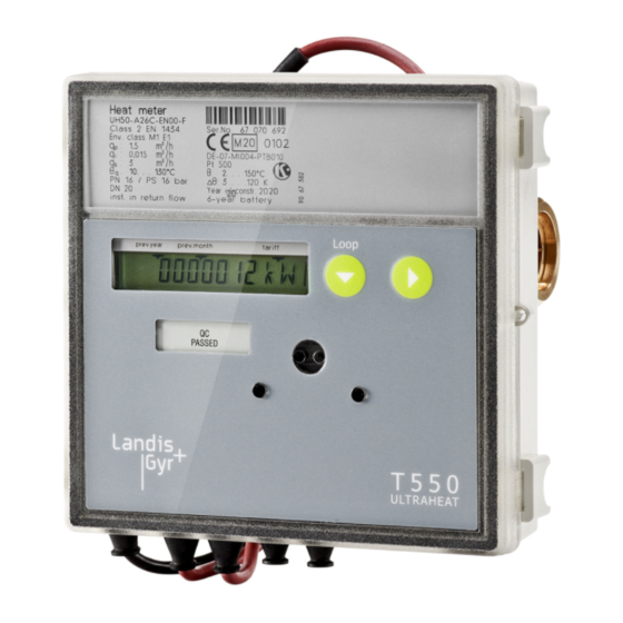
- Page 1 Ultrasonic heating and cooling meter T550 (UH50…) Residential, district heating, local heating plant ® (UH50…) ULTRAHEAT T550 ® (UH50…) ULTRACOLD T550 (UH50…) Flow sensor T550 Technical description 32 16 101 001 h Date: 23.08.2018 Landis+Gyr GmbH...
- Page 2 Outstanding features 2/49 Outstanding features Meter for measurement of flow and energy in a heat or cold circuit with water using the ultra- sonic principle. Important properties are: Non-wearing due to non-moving parts Measuring range of 1:100 according to EN1434:2014, 1:1.000 total range ...
-
Page 3: Table Of Contents
Contents 3/49 Contents General notes ____________________________________________________________ 5 Other available documentations ______________________________________________ 5 Safety information ________________________________________________________ 6 Technical data ___________________________________________________________ 8 Small meters (qp 0.6 – 2.5 m³/h) _____________________________________________ 10 Large meters with thread ___________________________________________________ 11 Large meters with flange ___________________________________________________ 12 Large meter qp 150 _______________________________________________________ 12 Installation _____________________________________________________________ 13 Installation Notes _________________________________________________________ 13... - Page 4 Contents 4/49 Threshold value tariff (tariffs T2, T3, T4, T5, T6) ________________________________ 34 Supplied quantity of energy (tariff T7) ________________________________________ 34 Returned quantity of energy (tariff T8) ________________________________________ 34 Heating/Cooling meter (tariff T9) ____________________________________________ 35 Tariff control via timer switch (tariff T10) ______________________________________ 35 Tariff control via M-Bus (tariff T11) __________________________________________ 35 Surcharge quantity tariff by means of return temperature (tariff T12) ________________ 35 Display of the tariff situation on the LCD ______________________________________ 35...
-
Page 5: General Notes
General notes 5/49 General notes Note In the following text, the term meter refers to heating meter, cooling meter and flow meter, unless they are otherwise differenti- ated. The meter is used as a meter for heating or cooling consumption measure- ment in systems with water. -
Page 6: Safety Information
Safety information 6/49 Safety information The meter may only be used in building service engineer- ing systems and only for the applications described. The local regulations (installation etc.) must be adhered to. The operating conditions according to the type plate must be complied with during use. - Page 7 Safety information 7/49 As far as disposal is concerned, the meter is a waste elec- tronic appliance in the sense of European Directive 2012/19/EU (WEEE) and it must not be disposed of as domestic waste. The relevant national, legal regulations must be observed as the appliance must be disposed of via the channels provided for this purpose.
-
Page 8: Technical Data
Technical data 8/49 Technical data General Measuring accuracy Class 2 or 3 (EN 1434) Environment class A (EN 1434) for indoor installation Mechanical class M1 *) Electromagnetic class E1 *) *) according to 2014/32/EU Directive on Measuring Instruments Ambient humidity <... - Page 9 Technical data 9/49 G/DN mbar DN20 DN20 DN20 DN25 DN25 DN40 DN50 15.4 DN50 14.3 DN65 24.4 DN80 31.6 DN100 56.0 DN150 1500 136.9 50*) Measurement insert 4 kg Tolerance of pressure lost: +/- 5%...
-
Page 10: Small Meters (Qp 0.6 - 2.5 M³/H)
Technical data 10/49 Small meters (qp 0.6 – 2.5 m³/h) Fig. 1: Overview dimensions overall length 110 mm (thread) Fig. 2: Overview dimensions overall length 130 mm (thread) Fig. 3: Overview dimensions overall length 190 mm (thread) Order-No. m³/h UH50-x03 UH50-x04 UH50-x05 G ¾... -
Page 11: Large Meters With Thread
Technical data 11/49 Fig: Overview dimensions overall length 190 mm (flange) Overall Order-No. Connection length m³/h UH50-x08 DN20 UH50-x24 DN20 UH50-x39 DN20 Large meters with thread Alternative mounting option Fig. 5: Overview dimensions of large meters with thread Order-No. m³/h UH50-x45 G 1¼... -
Page 12: Large Meters With Flange
Technical data 12/49 Large meters with flange Fig. 7: Overview dimensions of large meters with flange No. of Order- Øc Ød Øe holes m³/h UH50-x46 UH50-x52 UH50-x61 UH50-x65 UH50-x69 UH50-x70 UH50-x74 UH50-x82 UH50-x83 Large meter qp 150 Fig. 8: Overview all dimensions of large meter qp 150 No. -
Page 13: Installation
Installation 13/49 Installation To install the meter proceed as follows: Determine the place of installation in line with the inscription on the meter. Note: At a heating meter or combined heating/cooling meter the mounting place of the flow sensor cold side is equivalent to return flow. -
Page 14: Installation Notes For Sensor Adapter Set (Temperature Sensor Directly Immersed)
Installation 14/49 Welding sleeve with pockets Fig. 10: Installation with pockets (recommended greater than or equal to qp 10) Fig. 11: Installation for circulation with admixing; placement of temperature sensors Fig. 12: Installation for circulation with throttling configuration for example (flow sensor in flow direction upstream control valve / differential pressure regulating valve) Installation notes for sensor adapter set (temperature sensor directly immersed) A mounting set is included for meters with 5.2 ×... -
Page 15: 4.1 Installation For Cooling Metering
Installation 15/49 4.1 Installation for cooling metering When installing as a cooling meter it is essential that the black cover on the measuring tube is pointed to the side or down-wards in order to avoid prob- lems with condensation. Fit the immersion sleeves so that the temperature sensor is positioned vertically downwards or horizontally. -
Page 16: Dimension Of Electronic Unit
Dimension of electronic unit 16/49 Dimension of electronic unit Fig. 15: Dimensions of electronic unit Fig. 16: Plan view and cross section of adapter plate... -
Page 17: Operating Elements
Operating elements 17/49 Operating elements Fig. 17: Operating elements Name Description Note Service button To call up the pa- Accessible after removing rameterization op- the cover. eration of the me- ter. Button 2 Switches next display value within a loop. Button 1 Switches next loop. -
Page 18: 6.1 Displaying Current Meter Status
Operating elements 18/49 6.1 Displaying current meter status The meter displays the current meter status in kWh, MWh, MJ or GJ. Note: In order to prevent reading errors, the decimal places of the values displayed are marked with a frame. Note: Calibrated values can be recognized by an additionally displayed star symbol. -
Page 19: Service Loop 1 „Loop 1
Operating elements 19/49 Service loop 1 „LOOP 1“ Service loop 1 displays the details of the current measurement. The LCD shows the following values one after the other: Head of the loop Current flow Current power TV current temperature hot side, TR current temperature cold side;... -
Page 20: Service Loop 3 („Loop 3")
Operating elements 20/49 3 („LOOP 3“) Service loop Service loop 3 displays the monthly values. Head of the loop … … Set day for July 2011 The LCD displays the following values one after the other: Energy on the set day Tariff register 1 on the set day Volume on the set day Max. -
Page 21: Service Loop 4 („Loop 4")
Operating elements 21/49 4 („LOOP 4“) Service loop Service loop 4 displays appliance parameters. The LCD displays the following values one after the other: Head of the loop Current tariff, in 2-sec. cycles with threshold value 1 Measurement interval flow Measurement interval temperature Module 1: M-Bus module M-Bus primary address 1... -
Page 22: Previous Year's Values
Operating elements 22/49 Previous year’s values The meter saves the following values on the yearly set day Energy (meter status) Volume (meter status) Tariff register (meter status) Missing time (meter status) Flow measurement time (meter status) and the maxima with date stamp for ... -
Page 23: Resolution Of The Display
Resolution of the display 23/49 Resolution of the display Note: The number of places after the decimal point of a value is based on the chosen measurement path and the chosen dimension. -
Page 24: Power Supply
Power supply 24/49 Power supply The meter can be supplied with power via a battery or via power supply mod- ules as preferred. Battery and power supply are replaceable at any time. Options: 6 years battery 11 years battery ... -
Page 25: Power Supply Modules
Power supply 25/49 Power supply modules General Pollution degree per EN 61010 (no or only dry, non- conductive soiling) Ambient temperature + 5...+55°C Storage temperature -20…+60 °C Back-up time during power > 20 minutes failure (power reserve) safety extra-low voltage °... -
Page 26: Communication
Communication 26/49 Communication Electronic unit interfaces The meter is equipped with an optical interface in accordance with EN 62056- 21:2002 as standard. You can additionally use the remote reading with up to 2 of the following communication modules: Pulse module ... -
Page 27: Permissible Combinations Of Modules
Communication 27/49 Permissible combinations of modules Analog module M-Bus module Step 1 Slot for module #2 is equipped with... MB G4 M-Bus module MB MI M-Bus module Pulse CL module Radio module module GPRS GPRS module LoRa LoRaWAN module Pulse module "standard"... -
Page 28: Terminals
Communication 28/49 Terminals 2-pole or 4-pole terminals are used for connection of the external cables to the modules. Outer diameter of the cable 4 … 6 mm Connection capacity rigid or flexible 0.2 … 2.5 mm² flexible with wire end ferrule 0.25 …... -
Page 29: Cl Module
Communication 29/49 CL module With the CL module it is possible to read out the meter by wire e.g. on the doorstep through a point-to-point connection. Display in LCD CL (Current Loop) Classification acc. to EN 62056-21 Mode B Type passive current loop Baud rate 2400 Baud, fix... -
Page 30: M-Bus Module Mi With 2 Pulse Inputs
Communication 30/49 M-Bus module MI with 2 pulse inputs The M-Bus module enables the meter to communicate with an M-Bus center in order to transmit measured values. In addition to a possible voltage supply from the M-bus connection, the “MI” module is equipped with a battery. This powers the module processor and the pulse input, if no M-bus voltage is ap- plied. -
Page 31: Analog Module
Communication 31/49 rigid or flexible 0.25 ... 0.75 mm² flexible with wire end ferrule 0.25 ... 0.75 mm² Permissible cable length Max. 10 m Analog module The analog module converts the measured value from the meter to an analog signal. 12 …... -
Page 32: Radio Module 868 Mhz Lorawan (Cmi4110)
Communication 32/49 **) If the battery of the meter is of any other type, it must be replaced by a battery of type D. This battery life time is valid for the standard data telegrams (P600, P601) and T550 with standard measuring interval for flow and temperature. Radio module 868 MHz LoRaWAN (CMi4110) Note: For T550 with firmware ≥... - Page 33 Communication 33/49 Connection M-Bus Screw terminal 0.25 to 1.5 mm² Power supply via power supply (meter) Nominal voltage 100-240 V AC Voltage range -20 % to +15 % of nominal voltage Frequency 50/60 Hz Power consumption (Max) < 2.5 VA Power consumption (Nom) <...
-
Page 34: Tariff Control (Optional)
Tariff control (optional) 34/49 Tariff control (optional) Note: The tariffs can only be parameterized using the service software. Note: The summation of quantity of energy and volume in the standard registers is performed independently of the tariff situation. The following options are available for tariff control: Threshold value tariff (tariffs T2, T3, T4, T5, T6) The threshold value tariff can be derived from ... -
Page 35: Heating/Cooling Meter (Tariff T9)
Tariff control (optional) 35/49 Heating/Cooling meter (tariff T9) In tariff register 1, the measured quantity of cold; in tariff register 2, the meas- ured quantity of heat is summated. In both cases a threshold can be defined via the temperature hot side (“cold threshold”, “heat threshold”). ... - Page 36 Tariff control (optional) 36/49 for T2, T3, T4, T5, T6 in 2-sec. cycles with threshold value 1/2/3 for T7 for T8 for T9; in 2-sec. cycles for T10; switching times in 2-sec. cycles for T11 for T12 The contents of the tariff registers are displayed in the user loop after the quantity of energy.
-
Page 37: Error Messages
Error messages 37/49 Error messages The meter continuously runs a self-diagnosis and can thus recognize and dis- play various installation or meter error messages. Error Error Service guidelines code Check flow or installation direction; Incorrect flow direction correct if necessary if necessary in exchange with: Check installation point of the tem- DIFF... -
Page 38: Log Functions
Log functions 38/49 Log functions In the internal logbook, metrologically relevant events (errors, states, actions) are stored in chronological order with their time of occurrence. The events ac- quired are predefined. The data of the logbook cannot be deleted. Each event is stored in a separate 4-level shift register; the overflows are transferred to a 25-level circulating buffer. - Page 39 Log functions 39/49 Monthly set das parameterized Master reset performed All times deleted Missing time deleted Maxima deleted Note: Read-out is performed via the optical interface with the service software.
-
Page 40: Data Logger (Optional)
Data logger (optional) 40/49 Data logger (optional) The data logger permits the archiving of data that the user can select from a predefined set of values. The data logger contains four archives whose 8 channels can be assigned. The data can be assigned to any of the channels. Storage Averaging time Archive... -
Page 41: Additional Options
Additional options 41/49 Additional options Options: Version with data logger Heating meter for mounting place hot side Operable as flow meter Cooling meter 6/12 °C Combined heat/cold meter Length of the control cable between measurement tube and electronic unit up to 5 m ... -
Page 42: Order Codes (Type Number Key)
Order codes (type number key) 42/49 Order codes (type number key) Mandatory data for the order designation (label plate Mandatory data for Hardware- data) dependent features Type Code: U H 5 0 - X Y Y X - Y Y X X - Y X X - Y X Y X - Y Y X 1. - Page 43 PN25, connection flanged DN 80 5. Manufacturer’s label Code Nominal flowrate 60 m³/h, length 360 mm, nominal Logo Landis+Gyr pressure PN16, connection flanged DN 100 Other labels on request Nominal flowrate 60 m³/h, length 360 mm, nominal pressure PN25, connection flanged DN 100 6.
- Page 44 44/49 CL module Display: kWh (until qp 10) M-Bus module 30s Display: MWh with 3 decimal places (as of qp 15 with 2 decimal places; as of qp 150 with 1 decimal place) M-Bus module G4 Display: MJ (until qp 2.5) M-Bus module G4-MI with 2 pulse inputs Display: GJ with 3 decimal places (as of qp 3.5 with 2 Pulse module with OptoMOS...
-
Page 45: Additional Ordering Information On Radio Module 868 Mhz (Wireless M-Bus En13757-4, Oms V2.0)
45/49 Additional ordering information on radio module 868 MHz (wireless M-Bus EN13757-4, OMS v2.0) For OMS v2.0, radio mode T1, security profile A Ordering example: (encryption mode 5) Necessary additional ordering information: Order example OMS Wireless M-Bus module 868 MHz with integrated / external antenna: UH50-XYY0-Y 00-YXEX-YYX 2 - 9 - 1 - P601... -
Page 46: Additional Ordering Information On Radio Module 868 Mhz (Wireless M-Bus En13757-4, Oms V4.1.2)
46/49 Additional ordering information on radio module 868 MHz (wireless M-Bus EN13757-4, OMS v4.1.2) For OMS v4.1.2 (BSI), radio mode T1, security Ordering examples: profile B (encryption mode 7) or radio mode C1 Order example OMS Necessary additional ordering information: Wireless M-Bus module 868 MHz with integrated / external antenna 7 - 0 - 3 -... -
Page 47: Pressure Loss
Pressure loss 47/49 Pressure loss Nominal flowrate Overall Pressure loss Kv-Factor Graph in Connection at Δp 1 bar length at qp diagram mbar 110, 190 G 1, DN20 130, 190 G 1, DN20 G 1, DN20 DN25 , DN25 200, 300 G 2, DN40 DN50 DN50... - Page 48 Pressure loss 48/49 Alternatively, the value can be taken from the diagram. F G H 1000 flow rate in m³/h 21.02.2017...
- Page 49 49/49 Landis + Gyr GmbH Humboldtstrasse 64 90459 Nuremberg Germany www.landisgyr.eu...
Need help?
Do you have a question about the ULTRACOLD T550 and is the answer not in the manual?
Questions and answers