Landis+Gyr ULTRAHEAT T550 Manual
Hide thumbs
Also See for ULTRAHEAT T550:
- Technical description (49 pages) ,
- Operating instructions (3 pages) ,
- Installation instructions manual (8 pages)

Related Manuals for Landis+Gyr ULTRAHEAT T550


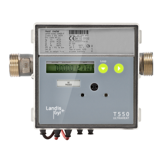
Summary of Contents for Landis+Gyr ULTRAHEAT T550
- Page 1 Calculator T550 (UC50…) Residential, district heating, local heating plant ® ULTRAHEAT T550 (UC50…) ® ULTRACOLD T550 (UC50…) Technical description 32 19 101 001 a Datum: 05.05.2015 Landis+Gyr GmbH...
- Page 2 Outstanding features 2/39 Outstanding features • Also operable as combined heat / cooling meter calculator • Mounting place of flow sensor: hot or cold side possible • Big range of communication modules for remote readout and system integration • 2 module slots for using 2 communication modules coincidental •...
-
Page 3: Table Of Contents
Contents 3/39 Contents General notes ____________________________________________________________ 5 Other available documentations ______________________________________________ 5 Safety Information ________________________________________________________ 6 Technical Data ___________________________________________________________ 7 Installation ______________________________________________________________ 8 Examples of installation _____________________________________________________ 8 Temperature sensors ____________________________________________________ 9 Connection of flow sensor _______________________________________________ 10 Dimension of electronic unit _______________________________________________ 11 Operating elements ______________________________________________________ 12 LCD ________________________________________________________________ 13 Display values “LOOPs”... - Page 4 Contents 4/39 Tariff control via M-Bus (tariff T11) __________________________________________ 30 Surcharge quantity tariff by means of return temperature (tariff T12) ________________ 30 Display of the tariff situation on the LCD ______________________________________ 30 Error messages __________________________________________________________ 32 Log functions ___________________________________________________________ 33 Data logger (optional) _____________________________________________________ 34 Additional options _______________________________________________________ 35 Order codes (type number key) _____________________________________________ 36...
-
Page 5: General Notes
General notes 5/39 General notes Note In the following text, the term calculator refers to both heat meter calculator and cooling meter calculator, unless they are otherwise differentiated. The calculator is used as a calculator for heating or cooling consumption measurement in systems with water. -
Page 6: Safety Information
Safety Information 6/39 Safety Information The calculator may only be used in building service engi- neering systems and only for the applications described. The local regulations (installation etc.) must be adhered to. Adhere to the operating conditions according to the dial plate during use. -
Page 7: Technical Data
Technical Data General Environment class A (EN 1434) for indoor installation Mechanical class M1 *) Electromagnetic class E1 *) *) according to 2004/22/EC Directive on Measuring Instruments Ambient humidity <93 % rel. humidity at 25 °C, without condensation Max. height 2000 m above sea level Storage temperature -20 …... -
Page 8: Installation
Installation 8/39 Installation Note: The mounting place and the pulse value of flow sensors with pulse output must correspond to the in the calculator set val- ues (see LOOP 2). Service loop 2 “LOOP 2“ Service loop 2 displays the installation details. Head of the loop Mounting place of the flow sensor: cold side or Mounting place of the flow sensor: hot side... -
Page 9: Temperature Sensors
Installation 9/39 Welding sleeve with pockets Fig. 2: Installation with pockets (recommended greater than or equal to DN32) Temperature sensors Note: The temperature sensor type PT 100 / 500 must correspond to the information on the dial plate. Note: If detachable temperature sensors are used they must have their own calibration or certification of conformity! Note: The maximum cable length of the temperature sensors is 10 m. -
Page 10: Connection Of Flow Sensor
Installation 10/39 Connection of flow sensor Note: The flow sensor must be installed at the same circuit as the temperature sensors. Note: When a polarity dependent pulse transmitter is used, take care of the correct orientation. • Connect the negative reference potential (-) or GND on the right spring-type terminal. -
Page 11: Dimension Of Electronic Unit
Dimension of electronic unit 11/39 Dimension of electronic unit Fig. 5: Dimensions of electronic unit Fig. 6: Plan view and cross section of adapter plate... -
Page 12: Operating Elements
Operating elements 12/39 Operating elements Fig. 7: Operating elements Name Description Note Service button To call up the pa- Accessible after removing rameterisation op- the cover. eration of the me- ter. Button 2 Switches next display value within a loop. Button 1 Switches next loop. -
Page 13: 6.1 Lcd
Operating elements 13/39 6.1 LCD The calculator displays the current meter status in kWh, MWh, MJ or GJ. Note: In order to prevent reading errors, the decimal places of the values displayed are marked with a frame. Note: Calibrated values can be recognised by an additionally displayed star symbol. -
Page 14: Service Loop 1 "Loop 1
Operating elements 14/39 Service loop 1 “LOOP 1“ Service loop 1 displays the details of the current measurement. The LCD shows the following values one after the other: Head of the loop Current flow Current power Current temperature “hot“, “cold“ at 2-sec. -
Page 15: Service Loop 2 "Loop 2
Operating elements 15/39 Service loop 2 “LOOP 2“ Service loop 2 displays the installation details. The LCD shows the following values one after the other: Head of the loop Pulse value Mounting place of the flow cold side or hot side Note: At a heat meter calculator or combined heat / cold me- ter calculator the mounting place of the flow sensor cold side is equivalent to return. -
Page 16: Service Loop 4 "Loop 4
Operating elements 16/39 Max. power at period, at 2-sec. cycles with date stamp Max. temperatures „warm“ at period, at 2-sec. cycles with date stamp Max. temperatures „cold“ at period, at 2-sec. cycles with date stamp Missing time count on set day After the last display the previously selected set day is displayed once again. -
Page 17: Previous Year's Values
Parameterisation of pulse value and mounting place of flow sensor 17/39 Previous year’s values The meter saves the following values on the yearly set day • Energy (meter value) • Volume (meter value) • Tariff register (meter value) • Missing time (meter value) and the maxima with date stamp for •... -
Page 18: Display / Priority Rating
Display / priority rating 18/39 Display / priority rating The view is limited to up to 7 entries. At pulse parameterization, the display will adapt automatically. The display resolution can be selected from the following: Pulse Energy Energy Volume Flow Power [l/p] [MWh]... -
Page 19: Power Supply Requirements
Power supply 19/39 Power supply requirements Power supply Requirements (230 / 110 V (for measuring timebase Q = 4 years years years AC; 24 V s and time base T = 30 s) ACDC) Standard pulses, M-Bus read out (max. each 2x AA 15 min.), CL-Module M-Bus fast read out (max. -
Page 20: Communication
Communication 20/39 Communication Electronic unit interfaces The calculator is equipped with an optical interface in accordance with EN 62056-21:2002 as standard. You can additionally use the remote reading with up to 2 of the following communication modules: • Pulse module •... -
Page 21: Permissible Combinations Of Modules
Communication 21/39 Permissible combinations of modules Analog module M-Bus module Step 1 Slot for module #2 is equipped with... MB G4 M-Bus module MB MI M-Bus module Pulse CL module Radio module module GPRS GPRS module ZigBee module pulse module "standard"... -
Page 22: Terminals
Communication 22/39 Terminals 2-pole or 4-pole terminals are used for connection of the external cables to the modules. • Outer diameter of the cable 4 … 6 mm • Connection capacity rigid or flexible 0.2 … 2.5 mm² flexible with wire end ferrule 0.25 … 1.5 mm² conductor sizes 26 …... -
Page 23: M-Bus Module G4
Communication 23/39 10.2 M-Bus module G4 The M-Bus module enables the meter to communicate with an M-Bus centre in order to transmit measured values. Standard EN 1434-3; EN 13757-2, -3 Protocol EN 60870-5 Electrical isolation from calculator from the pulse inputs Connection Strip-back length 5 mm... -
Page 24: Analog Module
Communication 24/39 No-pulse duration (high) ≥ 50 ms Pulse value 0.01 litres/pulse, in steps of 10 000.00 litres/pulse, in steps of 0.01 litres/pulse Display and output in m , 7-digit; acc. to parameter setting with or with- out 1 decimal place Polarity yes, must be correct, if transmitter is of type “open collector”... -
Page 25: Radio Module 868 Mhz (Wireless M-Bus)
Communication 25/39 10.5 Radio module 868 MHz (wireless M-Bus) The radio module 868 MHz enables the calculator to communicate with a cen- tre (receiver) using 868 MHz radio frequency. The radio module 868 MHz supports as well OMS ) as DSMR ) compliant data transfer. -
Page 26: Gsm Module
Communication 26/39 10.6 GSM module The GSM module is intended for wireless data transmission (remote readout) in the form of SMS messages based on the GSM network ). In addition, a pe- riod for automatic logon or data transmission can be configured between 6 minutes and 45 days. -
Page 27: Gprs Module
Communication 27/39 10.7 GPRS module The GPRS module is used for data acquisition over a mobile network ), using open standard protocols ) in push mode (as Email, HTTP, FTP, SMS) or pull mode as transparent M-Bus (GSM, TCP). The integration into billing systems happens via selectable report templates. -
Page 28: Zigbee Module
Communication 28/39 10.8 ZigBee module Das ZigBee module enables the meter to communicate with a ZigBee Smart Energy Coordinator/Gateway with Trust Centre in order to transmit measured values. Standard IEE 802.15.4 Protocol ZigBee Pro Smart Energy (SE) 1.1 End Point Device Frequency 2.4 GHz 16 5MHz channels Chipset... -
Page 29: Tariff Control (Optional)
Tariff control (optional) 29/39 Tariff control (optional) Note: The tariffs can only be parameterized using the service software. Note: The summation of quantity of energy and volume in the standard registers is performed independently of the tariff situation. The following options are available for tariff control: Threshold value tariff (Tariffs T2, T3, T4, T5, T6) The threshold value tariff can be derived from •... -
Page 30: Heat / Cooling Meter (Tariff T9)
Tariff control (optional) 30/39 Heat / cooling meter (tariff T9) In tariff register 1, the measured quantity of cold; in tariff register 2, the meas- ured quantity of heat is summated. In both cases a threshold can be defined via the temperature hot side (“cold threshold”, “heat threshold”). •... - Page 31 Tariff control (optional) 31/39 for T2, T3, T4, T5, T6 in 2-sec. cycles with threshold value 1/2/3 for T7 for T8 for T9; in 2sec. cycles for T10; switching times in 2-sec. cycles for T11 for T12 The contents of the tariff registers are displayed in the user loop after the quantity of energy.
-
Page 32: Error Messages
Error messages 32/39 Error messages The calculator continuously runs a self-diagnosis and can thus recognise and display various installation or meter error messages. Error Error Service guidelines code Check installation point of the tem- DIFF Negative temperature differ- perature sensors; exchange if nec- ence essary if necessary in exchange with:... -
Page 33: Log Functions
Log functions 33/39 Log functions In the internal logbook, metrologically relevant events (errors, states, actions) are stored in chronological order with their time of occurrence. The events ac- quired are predefined. The data of the logbook cannot be deleted. Each event is stored in a separate 4-level shift register; the overflows are transferred to a 25-level circulating buffer. -
Page 34: Data Logger (Optional)
Data logger (optional) 34/39 Data logger (optional) The data logger permits the archiving of data that the user can select from a predefined set of values. The data logger contains four archives whose 8 channels can be assigned. The data can be assigned to any of the channels. Storage Averaging time Archive... -
Page 35: Additional Options
Additional options 35/39 Additional options Options: • Version with data logger • Available for order as cooling meter calculator with German national approval • Combined heat / cooling meter calculator • Available for order for liquid mixtures (e. g. glycol / water) •... -
Page 36: Order Codes (Type Number Key)
Dial plate for Slovak Republic (Slovakian) four-wire technology, mounting place of flow sensor 5. Manufacturer’s label Code hot side (flow) Logo Landis+Gyr Calculator for cooling measurement, medium glycol, four-wire technology, mounting place of flow sensor Other labels on request hot side (return) 6. - Page 37 M-Bus module 30 s are directly immersed. Radio module 868 MHz *) Radio module 868 MHz with external antenna *) GPRS module GPRS module (incl. SIM card) Landis+Gyr GmbH Pulse module with OptoMOS Humboldtstrasse 64 M-Bus module G4 90459 Nuremberg Pulse module standard...
-
Page 38: Additional Ordering Information On Radio Module 868 Mhz (Wireless M-Bus)
Additional ordering information on radio module 868 MHz (wireless M-Bus) 38/39 Additional ordering information on radio module 868 MHz (wireless M- Bus) Necessary additional ordering information: 4. Data telegram Code Code Telegram radio standard P600 For OMS: Telegram mobile radio P601 1. -
Page 39: Additional Ordering Information For Glycol
Additional ordering information for glycol 39/39 Additional ordering information for glycol T550 can be used as a calculator (acc. EN1434, not calibrated) for (UC50…) determination of heat / cold flow volume of liquid mixtures (e.g. glycol/water). An adjustment can be performed with the service software. Order code: Available medium Continuation:...
Need help?
Do you have a question about the ULTRAHEAT T550 and is the answer not in the manual?
Questions and answers