Table of Contents
Advertisement
Quick Links
Installation Instructions
en
Note: In the following text, the term meter refers to
both the heat meter, the cooling meter and the flow
meter, unless they are otherwise differentiated.
1.
General
The meter left the factory in a faultless condition where safety
is concerned. Adjustments, maintenance work, replacement of
parts or repairs may only be carried out by specialist staff who
are aware of the associated hazards. The manufacturer will
provide additional technical support on request. Calibration
relevant security seals on the meter must not be damaged or
removed. Otherwise, the warranty and calibration validity of the
meter will no longer apply.
•
Keep the packaging so that you can transport the meter in
its original packaging following expiry of the calibration va-
lidity.
•
Lay all cables at a minimum distance of 500 mm to high
voltage and high frequency cables.
•
A relative humidity of < 93 % at 25 °C is permissible (with-
out condensation).
•
Avoid cavitation in the whole system due to overpressure
i.e. at least 1 bar at qp and approx. 3 bar at qs (applies for
approx. 80 °C).
•
The 110 V / 230 V network parts correspond to protection
rating II so that the line voltage does not need to be dis-
connected when changing the meter.
2.
Safety Information
The meter may only be used in building service engi-
neering systems and only for the applications de-
scribed.
The local regulations (installation etc.) must be ad-
hered to.
The operating conditions according to the type plate
must be complied with during use. Non-compliance
can result in hazardous situations and the expiry of all
claims arising from liability for defects as well as liabil-
ity based on any expressly granted guarantees.
Requirements for circulating water (CEN/TR 16911:
2016).
The meter is only suitable for circulating water in
heating systems.
The meter is not suitable for drinking water.
Do not lift the meter by the electronic unit.
Be aware of sharp edges on the thread, flange and
measuring tube.
Only personnel, trained in the installation and opera-
tion of meters in heating and cooling systems, may
install and remove the meter.
Only install or remove the meter when the pipes are
pressure-less.
After installing the meter, check the leak-tightness of
the system.
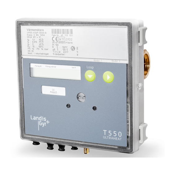
Landys+Gyr GmbH
Ultrasonic heat and cooling meter
®
ULTRAHEAT
T550
(UH50...)
®
ULTRACOLD
T550
(UH50...)
3.
To install the meter, proceed as follows:
•
•
•
•
Subject to change without prior notice
Warranty and calibration validity will lapse if the cali-
bration relevant security seals are broken.
Only clean the meter from outside with a soft, lightly
wetted cloth. Do not use any spirit or cleaning solvent.
The 110 V / 230 V connections may only be made by
an electrician.
The meter may only be powered up once the installa-
tion has been completed. There is otherwise a danger
of electronic shock on the terminals.
A defective or obviously damaged appliance must be
disconnected from the power supply immediately and
replaced.
As far as disposal is concerned, the meter is a waste
electronic appliance in the sense of European Di-
rective 2012/19/EU (WEEE) and it must not be dis-
posed of as domestic waste. The relevant national,
legal regulations must be observed as the appliance
must be disposed of via the channels provided for this
purpose. The local and currently valid legislation must
be observed.
The meter contains lithium batteries. Do not dispose
of the meter and the batteries with domestic waste.
Observe the local stipulations and laws on disposal.
You can return the lithium batteries to the manufac-
turer for appropriate disposal following use. When
shipping please observe legal regulations, in particu-
lar, those governing the labelling and packaging of
hazardous goods.
Do not open the batteries. Do not bring batteries into
contact with water or expose to temperatures above
80 °C.
The meter does not have any lightning protection.
Ensure lightning protection via the in-house installa-
tion.
Only fit one compartment for the power supply. Do not
remove the red locking hatch.
Installation
Determine the place of installation in line with the inscrip-
tion on the meter.
Note: At a heat meter or combined heating/cooling
meter the mounting place of the flow sensor cold side
is equivalent to return. The mounting place of the
flow sensor hot side is equivalent to flow.
Note: At a cooling meter the mounting place of the
flow sensor hot side is equivalent to the return. The
mounting place of the flow sensor cold side is
equivalent to flow.
Observe the dimensions of the meter and check whether
there is sufficient space available.
Rinse the system thoroughly before installing the meter.
Fit the meter vertically or horizontally between two slide
valves so that the arrow on the housing and the flow direc-
tion match. Also observe the installation situations and the
following examples of installation.
08.11.2018
Translation
T550
(UH50...)
08.11.2018
1
Advertisement
Table of Contents

Related Manuals for Landis+Gyr UH50 Series


Summary of Contents for Landis+Gyr UH50 Series
- Page 1 08.11.2018 Translation Installation Instructions Ultrasonic heat and cooling meter ® ULTRAHEAT T550 (UH50…) ® ULTRACOLD T550 (UH50…) T550 (UH50…) Warranty and calibration validity will lapse if the cali- Note: In the following text, the term meter refers to bration relevant security seals are broken. both the heat meter, the cooling meter and the flow meter, unless they are otherwise differentiated.
- Page 2 Fig. 3: Installation for circulation with admixing; placement of temperature sensors ceed 55 °C. Avoid direct sunlight. For water temperatures between 10 °C and 90 °C you can fit the electronic unit on the volume measurement unit or on the wall. Landis+Gyr GmbH Subject to change with prior notice 08.11.2018...
- Page 3 Plug the connection cable for low voltages into the plug connector on the PCB. Note: Only cables with diameter 5.0 ... 6.0 mm for the 24 V ACDC version. Fig. 9 Landis+Gyr GmbH Subject to change with prior notice 08.11.2018...
- Page 4 The communication modules are connected via a 6-pole reac- tion-free connector so that installation or replacement is possi- ble at any time. To install a communication module, proceed as follows: • Put the communication module into the correct position. Landis+Gyr GmbH Subject to change with prior notice 08.11.2018...
- Page 5 This means that incorrect values can also be entered (e. g. month > 12). Note: Remove the housing cover temporarily in order to operate the service button. Note: The meter can be parameterized even if the mod- ules have not yet been installed. Landis+Gyr GmbH Subject to change with prior notice 08.11.2018...
- Page 6 Recommendation: Reset the maxima and the missing time. • Replace the measurement insert by another measurement insert. If the measurement insert is not installed immediately, opening must be closed with the provided interim cover (available as accessory). Landis+Gyr GmbH Subject to change with prior notice 08.11.2018...
-
Page 7: Error Messages
Warning: All screws “a” (see figure 15) and “b” (see they are directly immersed. figure 16) must be screwed. Error messages for incorrect installation: Landis+Gyr GmbH Humboldtstrasse 64 Error “incorrect flow direction (negative)“ 90459 Nuremberg Check that the flow direction arrows on the volume measure- Germany ment unit match the flow direction of the system.
Need help?
Do you have a question about the UH50 Series and is the answer not in the manual?
Questions and answers