Table of Contents
Advertisement
Quick Links
Advertisement
Table of Contents

Subscribe to Our Youtube Channel
Related Manuals for Spirax Sarco TN2000RH


Summary of Contents for Spirax Sarco TN2000RH
- Page 1 3270049/3 IM-P327-02 CH Issue 3 TN2000 Series Pneumatic Piston Actuators Installation and Maintenance Instructions 1. Safety information 2. General product information 3. Installation 4. Maintenance 5. Spare parts © Copyright 2015 IM-P327-02 CH Issue 3 Printed in France...
-
Page 2: Safety Information
European Pressure Equipment Directive 97 / 23 / EC. This product has been specifically designed for use compressed air. The products' use on other fluids may be possible but, if this is contemplated, Spirax Sarco should be contacted to confirm the suitability of the product for the application being considered. -
Page 3: Protective Clothing
1.16 Returning products Customers and stockists are reminded that under EC Health, Safety and Environment Law, when returning products to Spirax Sarco they must provide information on any hazards and the precautions to be taken due to contamination residues or mechanical damage which may present a health, safety or environmental risk. -
Page 4: General Product Information
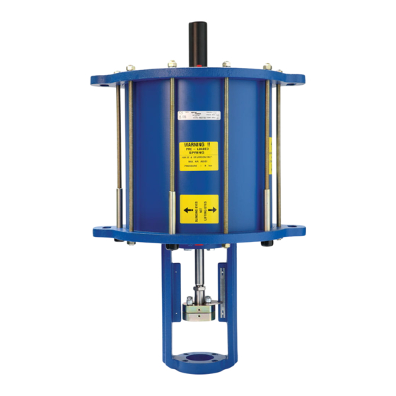
2. General product information 2.1 Description TN2000 series pneumatic piston actuators are suitable for use with DN125 to DN200 Spira-trol control valves of which three versions are available; Single acting (with spring), Double acting (with spring) and Double acting (no spring). The availability of these three versions meets the requirements of valves at various differential pressures and in a variety of applications. - Page 5 Note: When lifting the actuator only use a lifting sling through X1 to X4. 22, 27, 28 Fig. 1 IM-P327-02 CH Issue 3...
-
Page 6: Installation
Optimum Fig. 2 The air supply to the actuator must be ‘dry and free from oil’. Contact Spirax Sarco for more details with relation to composite tube / media compatibility. For high temperature conditions, insulate the control valve and pipework only to protect the actuator. - Page 7 25 and 33 Actuator yoke Valve spindle Valve bonnet Fig. 3 Adjust the connector (14) until it is touching the bottom connector (12 and 13). Re apply air to the actuator (to lift the actuator spindle (7)), screw the connector (14) down by 180°.
-
Page 8: Maintenance
3.2 Fitting the TN2000 SR or DR actuator to the valve: Remove the bottom connector (13). Manually push the valve spindle down to ensure the valve plug is on the valve seat. Ensure that the indicator scale (22) is facing the same way as the valve name-plate. Locate the actuator yoke on the valve bonnet and fit securing screws to a torque of 40 Nm. - Page 9 25 and 33 Actuator yoke Valve spindle Valve bonnet Fig. 4 IM-P327-02 CH Issue 3...
- Page 10 4.2 Replacing the 'O' rings (SE and DE actuators) Note: Remove the actuator from the valve as described in Section 4.1. Note: There are 5 long securing nuts that must be removed last to ensure that the spring tension is removed. Loosen and remove the 5 securing nuts and washers (23 and 32) on the threaded bar (19).
- Page 11 4.3 Replacing the 'O' rings (SR and DR actuators) Note: Remove the actuator from the valve as described in Section 4.1 Note: There are 5 long securing nuts that must be removed last to ensure that the spring tension is removed. Loosen and remove the connector (14), see Figure 4.
- Page 12 Note 4: A new product label will be required and fitted over the existing label if a conversion has been done. Contact Spirax Sarco with the new product details, and a new label can be supplied. As a temporary measure amend the existing label with a permanent marker stating failure mode and suffix lettering (E or R).
- Page 13 15 and 16 5 x long securing nuts 17 15 and 16 Fig. 7 TN2000E 15 and 16 17 5 x long securing nuts 15 and 16 Fig. 8 TN2000R IM-P327-02 CH Issue 3...
- Page 14 Note 4: A new product label will be required and fitted over the existing label if a conversion has been done. Contact Spirax Sarco with the new product details, and a new label can be supplied. As a temporary measure amend the existing label with a permanent marker stating failure mode and suffix lettering (E or R).
- Page 15 15 and 16 17 5 x long securing nuts 15 and 16 Fig. 9 TN2000R 15 and 16 5 x long securing nuts 17 15 and 16 Fig. 10 TN2000E IM-P327-02 CH Issue 3...
- Page 16 4.6 Fitting the handwheel to TN2000RH actuators Remove the cover (21) from the actuator, see Figure 11. Remove the dust cap from the top of the handwheel assembly Insert the plunger and tighten the securing bolt Ensure the indicator is at the highest point.
- Page 17 4.7 Fitting the handwheel to TN2000 EH actuators Remove the cover (21) from the actuator, see Figure 12. Remove the dust cap from the top of the handwheel assembly Fit the handwheel spacer over the spindle and locate it on the bearing and seal insert. Ensure the indicator is at the lowest point.
-
Page 18: Spare Parts
How to order spares Always order spares by using the description given in the column headed 'Available spares' and state the actuator model. Example: 1 - 'O' ring kit for a Spirax Sarco TN2277SE pneumatic piston actuator. Fig. 13 Fig. 14... - Page 19 15, 29, 30 and 31 22, 27 and 28 Fig. 15 IM-P327-02 CH Issue 3...
- Page 20 IM-P327-02 CH Issue 3...
Need help?
Do you have a question about the TN2000RH and is the answer not in the manual?
Questions and answers