Advertisement
4033150/7
Installation and Maintenance Instructions
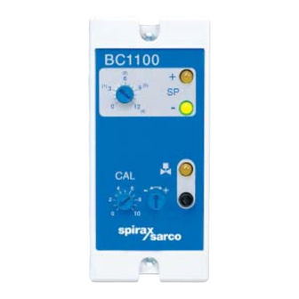
BC1100
(2)
6
(1)
3
9
0
12
_
4
6
2
8
0
10
Printed in the UK
IM-P403-47 AB Issue 7
BC1100
Controller
+
(3)
SP
- -
(4)
+
1. General
safety information
2. General
product information
3. Installation
4. Setting up the controller
5. Wiring diagram
6. Commissioning
7. Maintenance
8. Fault finding
IM-P403-47
AB Issue 7
© Copyright 2003
1
Advertisement
Table of Contents

Subscribe to Our Youtube Channel
Related Manuals for Spirax Sarco BC1100


Summary of Contents for Spirax Sarco BC1100
- Page 1 4033150/7 IM-P403-47 AB Issue 7 BC1100 Controller Installation and Maintenance Instructions 1. General safety information BC1100 2. General product information 3. Installation 4. Setting up the controller 5. Wiring diagram 6. Commissioning 7. Maintenance 8. Fault finding Printed in the UK ©...
-
Page 2: General Safety Information
1. General safety information Your attention is drawn to Safety Information Sheet IM-GCM-10 as well as to any National or local regulations. Safe operation of the product depends on it being properly installed, commissioned and maintained by a qualified person in compliance with the operating instructions. It is essential to comply with general installation and safety instructions for pipeline and plant construction, as well as to make proper use of tools and safety equipment. -
Page 3: General Product Information
As well as the relay output, the BC1100 has a 4 - 20 mA (or 0 - 20 mA) output. The output represents the controller range and may be used for remote TDS display, as a chart recorder input, or as an input to a computer monitoring system. -
Page 4: Technical Data
The controller opens the blowdown valve periodically to purge the system and allow a sample of boiler water to pass the sensor. The electrical conductivity of this sample is compared with the set point selected on the controller front panel. If the conductivity is lower than the set point, the controller allows the blowdown valve to close. -
Page 5: Installation
Rocking the controller in the vertical plane will ease removal. The controller must be installed in a suitable industrial control panel or fireproof enclosure to provide environmental protection (pollution degree 2). Spirax Sarco can provide suitable plastic or metal enclosures (for the standard controller only). -
Page 6: Setting Up The Controller
4. Setting up the controller 4.1 Setting up the controller The controller is supplied set up as follows: 230 V mains supply. 1200 - 12 000 µS /cm. 10 second purge. Valve not pulsed. 4 - 20 mA output, held to 4 mA when the valve is closed. Range Range 400 - 4 000 / 1 200 - 12 000... - Page 7 4.2 To change the mains supply voltage: Loosen the two cover clamping screws. Unplug the controller from its base. Remove the rear cover panel. Slide out the printed circuit board assembly. Move the voltage selector switch to the 115 V setting. See Figure 3. Replace the printed circuit board assembly.
-
Page 8: Wiring Diagram
Ensure that the screen is connected to the earth terminal of the probe and to the common terminal of the controller. Ensure the common terminal of the controller is not internally earthed. (All Spirax Sarco boiler controls are internally isolated from earth). - Page 9 /boiler shell is less than 1 W. to the probe body and earth Note: The UL version of the BC1100 is supplied with flying leads already attached. A proprietary terminal block is required to connect the controller to the field wiring.
-
Page 10: Wiring Notes
Note: Calibration must only be carried out when the blowdown valve is open. Press and hold down the purge button to open the valve. 1. Measure the TDS or conductivity of the boiler water. The Spirax Sarco MS1 conductivity meter is a suitable instrument for this purpose. -
Page 11: Maintenance
The controller may be checked for correct operation by substituting a resistor for the conductivity sensor, or by using the Spirax Sarco Probe Simulator. This will allow the various controller functions to be tested. - Page 12 IM-P403-47 AB Issue 7...
Need help?
Do you have a question about the BC1100 and is the answer not in the manual?
Questions and answers