Table of Contents
Advertisement
4033452 / 8
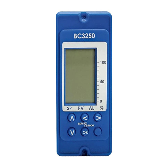
BC3250
Blowdown Controller
Installation and Maintenance Instructions
BC3250
100
50
0
%
SP
PV
AL
OK
IM-P403-89
EMM Issue 8
1.
Safety information
2.
User instructions and
delivery information
3.
System overview
4.
Mechanical installation
5.
Electrical installation
6.
Commissioning
- Quick set-up
- Full
7.
Communications
8.
Maintenance
9.
Fault finding
10. Technical information
- Default settings
11. Appendix
- Summary of the
Modbus protocol
12. Menu map
© Copyright 2017
Printed in GB
Commissioning password
Current legislation states that in order to prevent tampering and potentially
hazardous programming errors, access to the pass codes required to enter
commissioning mode should only be available to qualified and trained personnel.
Enter commissioning
This is done from the run mode by pressing and holding down the
The bar graphs will disappear and the display will show 'PASS
PASS
CODE' with '8888' at the bottom right corner of the screen. The
flashing leading digit indicates the position of the cursor. The
CODE
default, or factory set pass code is 7452 but this can be changed
from within the commissioning mode. The pass code can be
entered by using the
the flashing value and the
Pressing
will enter the pass code. If an incorrect pass code is
OK
used, the display automatically returns to the run mode.
8888
This page MUST be removed after
commissioning and kept in a safe,
access controlled location.
button for 5 seconds.
OK
and
buttons to increase or decrease
and
buttons to move the cursor.
IM-P405-89 EMM Issue 8
Advertisement
Table of Contents

Related Manuals for Spirax Sarco BC3250


Summary of Contents for Spirax Sarco BC3250
- Page 1 Current legislation states that in order to prevent tampering and potentially hazardous programming errors, access to the pass codes required to enter commissioning mode should only be available to qualified and trained personnel. BC3250 Enter commissioning Blowdown Controller This is done from the run mode by pressing and holding down the button for 5 seconds.
- Page 2 This product is suitable for Class A Environments (e.g. industrial). A fully detailed EMC Enables the water treatment engineer / specialist to calibrate the controller from the run assessment has been made and has the reference number UK Supply BH BC3250 2008. menu. A pass code is not required.
- Page 3 Symbols Equipment protected throughout by double insulation or reinforced insulation. Functional earth (ground) terminal, to enable the product to function correctly. Not used to provide electrical safety. Clean earth / ground. Safety earth. Caution, risk of electric shock. Caution, risk of danger, refer to accompanying documentation. Optically isolated current source or sink.
- Page 4 Determine the correct installation situation and direction of fluid flow. iv) Spirax Sarco products are not intended to withstand external stresses that may be induced by any system to which they are fitted. It is the responsibility of the installer to consider these stresses and take adequate precautions to minimise them.
-
Page 5: Protective Clothing
1.16 Returning products Customers and stockists are reminded that under EC Health, Safety and Environment Law, when returning products to Spirax Sarco they must provide information on any hazards and the precautions to be taken due to contamination residues or mechanical damage which may present a health, safety or environmental risk. -
Page 6: All Rights Reserved
Spirax-Sarco Limited. 2.1 General description The BC3250 is a blowdown controller for steam boilers. It controls TDS (total dissolved solids – salts in solution) by opening and closing a blowdown valve. It also controls a bottom blowdown valve, which removes precipitated solids from the bottom of the boiler shell. -
Page 7: Front Panel
2.2 Front panel The front panel has an LCD graphics display and five- button keypad: BC3250 Graphic display Horizontal arrows are used to toggle Scroll up menus between the Bar graph and the Trend graph Scroll down menus Clears any... -
Page 8: Lcd Display
2.4 LCD display After initially applying power to the product, it will automatically enter run mode. If a clean time has been set, a cleaning cycle will start. The current conductivity or TDS will then be displayed or 0000 if a purge time has been set. The display is divided into three sections: Four large digits, displaying the process variable and control parameters (last digit is blanked off or always reads zero). -
Page 9: Trend Graph
High alarm Highest process variable reached This can be reset by High alarm entering the commissioning hysteresis mode. Set Point (TDS) Set Point (hysteresis) Current process variable Graphical representation of the process variable in terms Fig. 4 SP and alarm bar of percentage of full scale. -
Page 10: Information Line
2.6 Information line The information line will show 'PPM' or 'US / CM' and will alternate with information about alarms or the TDS / Bottom Blowdown Valve status. If an alarm occurs, the TDS / Bottom Blowdown Valve status will not show. 'ALARM' will be shown first followed by the type of alarm. - Page 11 Information line details (in priority order): Alarm: ALARM - Indicates the alarm relay has been de-energised / released. ALM TEST - the operator is testing the alarm relay. The relay is either energised (shown without 'ALARM') or de-energised (shown with 'ALARM') for 5 minutes. See commissioning mode TEST-OUTPUT-ALARM menu.
-
Page 12: Viewing Parameters
2.7 Viewing parameters In run mode the general data is displayed on several screens, which can be accessed by pressing the buttons. The parameter will appear on the display, alternating with the value buttons. 4680 Process variable (PV) is displayed (current conductivity or TDS), in µS / cm or ppm, depending on user choice. - Page 13 Shows purge time (probe in pipeline). Flashes PURGE and 'S' (seconds). PURGE S Pressing the ' ' or ' ' opens the blowdown valve for the purge time or 1 minute. Shows the cleaning time selected. Flashes CLEAN and 'S' (seconds). Pressing the ' ' or ' ' to active the cleaning cycle and the blowdown...
-
Page 14: Receipt Of Shipment
Each carton should be unpacked carefully and its contents checked for damage. If it is found that some items have been damaged or are missing, notify Spirax Sarco immediately and provide full details. In addition, damage must be reported to the carrier with a request for their on-site inspection of the damaged item and its shipping carton. -
Page 15: System Overview
(plus a hysteresis value). 3.2 Inputs The BC3250 can accept a signal from a Spirax Sarco conductivity probe (CP10, CP30 or CP32) and a Pt100 temperature sensor. A Pt100 temperature sensor may be connected to the controller to display the boiler water temperature ( °C or °F) and provide temperature compensation (2% /... - Page 16 3.3 Outputs 3.3.1 Continuous output Used when the probe is mounted in the boiler. The probe is able to constantly monitor the conductivity from the probe tip to the boiler shell. Water High conductivity conductivity Hysteresis Valve open Blowdown Keeps valve open until Closed conductivity drops below Time...
-
Page 17: Other Features
This can be changed by the user if required. The BC3250 can communicate via an infrared link between adjacent boiler house controllers (Spirax Sarco products only). It is designated as a master or a slave unit as required – see Section 7 – 'Communications'. - Page 18 3.5 Typical applications - Boiler control systems (BCS) BC3250 Fig. 9 BCS1 system - smaller boiler BC3250 Fig. 10 BCS2 system - coil boiler IM-P403-89 EMM Issue 8...
- Page 19 BC3250 Fig. 11 BCS3 system - TDS control with integral take-off and continuous monitoring point from the side of the boiler. BC3250 Fig. 12 BCS4 system - TDS control with intermittent monitoring point from the side or the bottom of the boiler.
-
Page 20: System Description
The 500 mm head prevents flash steam flow in the bypass line. We recommend a 3-port diverter valve such as the Spirax Sarco I s o l a t i n g v a l v e QL. -
Page 21: Mechanical Installation
4. Mechanical installation Note: Read the 'Safety information' in Section 1 before installing the product. The product must be installed in a suitable industrial control panel or fireproof enclosure to provide impact and environmental protection. A minimum of IP54 (EN 60529) or Type 3, 3S, 4, 4X, 6, 6P and 13 (UL50 / NEMA 250 ) is required. - Page 22 4.3 Installation on a chassis plate: Drill holes in chassis plate as shown in Figure 15. Fit unit to chassis plate and secure with 2 screws, nuts and washers, using the slots provided at the top and bottom of the case. Warning: Do not drill the product case or use self-tapping screws.
- Page 23 Fig. 15 Ø 4.2 mm Ø 4.2 mm Chassis plate / panel 10 mm - cutout diagram 45 mm 112 mm 92 mm 22.5 10 mm Ø 4.2 mm Ø 4.2 mm 67 mm 120 mm 112 mm 8 mm 120 mm IM-P403-89 EMM Issue 8...
-
Page 24: Electrical Installation
Use only the connectors supplied with the product, or spares obtained from Spirax Sarco Ltd. Use of different connectors may compromise product safety and approvals. Connecting the mains supply incorrectly can cause damage and may compromise safety. - Page 25 10. It is important that the cable screens are connected as shown in order to comply with the electromagnetic compatibility requirements. 11. All external circuits must meet and maintain the requirements of double / reinforced installation as stated in IEC 60364 or equivalent. 12.
- Page 26 5.2 Mains wiring notes: 1. Read Section 5.1 before attempting to wire the supply to the product. 2. The wiring connections are identified on the terminal plugs. 3. Fuses should be fitted in all live conductors. 4. Double or reinforced insulation must be maintained between: Hazardous live conductors (mains and relays circuits) and Safety extra low voltages (All other components / connectors / conductors).
- Page 27 5.3 Blowdown valve wiring notes: Note: The protective earth must be connected in accordance with National or Local regulations Viewed from the underside, relays are shown in the power off position Link Link 230 / 115 Vac BCV30 Blowdown valve N Y1 Y2 22 See Section 5.2 Mains wiring notes Alarm...
- Page 28 Optional Limit Switch Limit Switch Box S1 ( Xs1 ) S2 ( Xs2 ) Valve Opening Valve Closing 2a valve opening 2b valve closing AVF234S BCV4x,6x,7x & 8x 0V (Common) * 24 Vac / dc ** Input Alarm Input Norm 3 A Fuse Fuse Fuse...
- Page 29 Optional Limit Switch Limit Switch Box S1 ( Xs1 ) S2 ( Xs2 ) Valve Opening Valve Closing 2a valve opening 2b valve closing Module 230V BCV4x,6x,7x & 8x N (Neutral) * 100-110 Vac / 230 Vac Input Alarm Input Norm 3 A Fuse Fuse...
- Page 30 Optional Limit Switch Limit Switch Box S1 ( Xs1 ) S2 ( Xs2 ) Valve Opening Valve Closing 2a valve opening 2b valve closing AVF234S BCV4x,6x,7x & 8x 0V ( Common ) * 24 Vac / dc ** Input Alarm Input Norm 3 A Fuse...
- Page 31 Optional Limit Switch Limit Switch Box S1 ( Xs1 ) S2 ( Xs2 ) Valve Opening Valve Closing 2a valve opening 2b valve closing Module 230V BCV4x,6x,7x & 8x N (Neutral) * 100-110 Vac / 230 Vac Input Alarm Input Norm 3 A Fuse Fuse...
-
Page 32: Probe Wiring
5.4 Signal wiring notes See Section 10, Technical Information, for terminal and cable specification. An earth current loop is created if a wire or screen is connected between two earth points that are at different potential (voltage). If the wiring diagram is followed correctly, the screen will only be connected to the earth at one end. - Page 33 5.6 Probe in blowdown (or condensate) line - CP10 For most applications the 1.25 m (4 ft) heat resisting probe cable will need to be extended using a junction box. If not, link terminals 50 to 51, and 52 to 53. Note: Whilst pairs of conductors are linked at the junction box, the four-wire connection is required to compensate for voltage drop.
- Page 34 5.11 EIA / TIA-485 communication wiring diagram The product can be connected as a slave to a two or four-wire EIA / TIA-485 multi-drop network. Slave(s) (Boiler controller) Remove link between terminals 91 and 90. H / D H / D Common Earth See wiring notes...
- Page 35 Slave(s) (Boiler controller) H/ D H/ D Add link between terminals 91 and 90 Common Earth See wiring notes Master Fig. 27 RS485 / Modbus half duplex circuit (view from the top) EIA / TIA-485 wiring notes continued: The bus common must be connected directly to protective ground / earth at one point only.
-
Page 36: General Information
If the calibration was incomplete the controller may not provide the correct control. The product has no battery. The programmed settings are held in non-volatile memory (Flash) and are written to after changing a parameter and pressing BC3250 Exit sub-menus Graphic display. -
Page 37: Changing Parameters
6.2 Commissioning mode navigation After the correct pass code has been entered the display shows: To exit the commissioning mode at any stage, press and hold the MODE button to return to the run mode. Pressing the buttons scrolls through the various first level menus. - Page 38 6.3 Commissioning - Quick set-up This section allows the user to carry out the minimum commissioning necessary to operate the system. It accepts the defaults set in the factory, so will only work if the original default settings have not been altered. See the default settings in Section 10, Technical information, to confirm. Settings can then be tailored to suit the individual requirements of the customer / application if required.
- Page 39 6.4 Commissioning - Full Sub-menus and their functions are outlined within this section, and enables the user to programme the unit. Additional information is given in the sub-menu notes where further choices can be made. 6.4.1 Main menu structure Allows the user to view and change the valve status MODE (OPEN or CLOSED).
- Page 40 6.4.2 MODE sub-menu Allows the user to switch from automatic or manual control of the valve. Entering this menu (press the button) will always show 'CLOSE' – flashing. The the buttons will toggle the state and can be selected by pressing the button.
- Page 41 6.4.4 INPUT menu Allows selection of the type of measurement to be performed. INPUT Temperature compensation. T COMP If no Pt100 is fitted, a constant temperature can be entered. e.g. 184 °C (default). INPUT Allows selection of all the TDS control features: Sensor type, purge, filter, range, set point, hysteresis, calibration, and calibration interval.
- Page 42 6.4.6 INPUT sub menu notes 6.4.6.1 INPUT – TDS – SENSOR – FLT MODE Only shown if the CP32 probe is selected. Allows selection of the action to be taken if the probe detects a fault. 'OFF' No action. 'CLEAN' If the probe is scaled then the time between probe conditioning cycles will change from the CLEAN-INTERVAL time set to 10 minutes, until the probe is clean.
- Page 43 Take a sample of the boiler water and measure its conductivity (in µS / cm) using a meter such as the Spirax Sarco MS1. If the controller is required to be calibrated as neutralised conductivity or TDS, neutralise the sample and measure again using the meter.
- Page 44 (the set point). 5 litres (1.3 US gallons) will be plenty for most systems. Use the Spirax Sarco MS1 conductivity meter to check the conductivity. Close both stop valves and open the drain valve and ‘water for flushing and calibration’...
- Page 45 6.4.7 OUTPUT sub-menu Allows the selection of the type of measurement to be performed. Selects standard or pulsed. Standard (valve remains open during OUTPUT blowdown cycle – default). Pulsed – valve open 10 seconds, closed DRIVE 20 seconds. Pulsed prevents the water level from falling too quickly in a small boiler, which could cause a low water alarm.
- Page 46 6.4.8 OUTPUT sub-menu notes OUTPUT DRIVE notes If standard (default) is selected the valve will remain open until the conductivity drops below the Set Point (plus the corresponding hysteresis). If 'pulsed' is selected the valve will open for 10 seconds and close for 20 seconds. The pulsed feature is suitable for use with solenoid or pneumatic valves only.
- Page 47 An automatic probe scale detect feature is available if a CP32 two-tip probe is fitted and selected. It selects the action taken by the controller to a probe with too high a resistance, caused, for example, by scaling. If 'CLEAN' or 'AL + CLEAN' is selected, the interval time is automatically set to 10 minutes until the scale is removed –...
- Page 48 6.4.9 TIMER sub-menu This timer controls the bottom blowdown intervals and their duration. It can be wired to a switch box on the blowdown valve actuator to monitor valve operation. An alarm can occur if the valve fails to close fully or lift off its seat within a certain period. The product cannot, however, be used to indicate that the valve has opened fully.
- Page 49 6.4.10 ALARM sub-menu ALARM An alarm is triggered at a set PV figure (TDS / conductivity). Hysteresis – 3% (default), 0 – 100% FS, 0.1% resolution. Prevents ALARM over-frequent switching of the alarm in a turbulent boiler. Do not set to PV HYST more than 15% unless exceptional operating conditions are present.
- Page 50 6.4.11 TEST sub-menu Allows access to the diagnostic tools. Turns on all the segments on the display. The screen should be TEST completely black if all pixels are working. Press the button to enter DISPLAY test input mode, or the button to exit the test mode and return to the main menu.
- Page 51 6.4.12 TEST INPUT sub-menu Allows access to the diagnostic features. TEST INPUT Displays the internal temperature of the microcontroller. INT TEMP TEST INPUT Displays the calculated water resistance in ohms, Kohms or Mohms. RESIST TEST Not visible if no Pt100 is fitted. Displays the equivalent operating INPUT temperature, measured by the Pt100 (if connected).
- Page 52 6.4.13 TEST OUTPUT sub-menu TEST Enables the output to be adjusted between 4 mA and 20 mA to test OUTPUT the system. RETRANS TEST OUTPUT Energises / de-energises the TDS valve relay for test purposes. VALVE TEST Energises / de-energises the bottom blowdown valve relay for test OUTPUT purposes.
-
Page 53: Infrared (Ir)
7. Communications 7.1 Infrared (IR) All products in the range can communicate via an infrared bus between adjacent controllers. It enables the parameters of up to seven products to be passed to a product fitted with an RS485 (products with a graphics display). The product connected to the RS485 network must be fitted on the left of all the slaves fitted to the IR bus (Figure 32) and have 'master' selected in the 'output-comms' menu. -
Page 54: Maintenance
8. Maintenance Note: Read the 'Safety information' in Section 1 before starting any maintenance. No special servicing, preventative maintenance or inspection of the product is required. During installation or maintenance, the rear of the product must be protected from environmental pollutants entering the product. Alternatively, the tasks can be performed in a dry clean environment. -
Page 55: Fault Finding
9. Fault finding WARNING: Before fault finding read the Safety information in Section 1 and the General wiring notes in Section 5.1. Please note that there are hazardous voltages present and only suitably qualified personnel should carry out fault finding. The product must be isolated from the mains supply before touching any of the wiring terminals. - Page 56 9.2 System faults Symptom Action 1. Switch off the mains supply to the product. 2. Check all wiring is correct. 3. Check external fuse(s) are intact. Replace if necessary. 4. Check the mains voltage is within specification. 5. Switch on mains supply. Display not If symptoms are still present return and replace the product.
-
Page 57: Error Message
9.3 Operational error messages Any operational errors that occur will be displayed in the run mode, on the alarms and errors screen. Error Cause Action message 1. Remove power from product. 2. Check that all wiring is correct. Power There has been fail. - Page 58 Error Cause Action message 1. Check the correct closing time has been entered in the INPUT - CLOSING menu. Blowdown valve 2. See VALVE FAILED TO OPEN. VALVE fails to close fully 3. Enter the commissioning mode and enter FAILED TO the correct passcode.* 4.
-
Page 59: Technical Information
10.2 Returning faulty equipment Please return all items to your local Spirax Sarco representative. Please ensure all items are suitably packed for transit (preferably in the original cartons). Please provide the following information with any equipment being returned: 1. - Page 60 10.4 Environmental General Indoor use only Maximum altitude 2 000 m (6 562 ft) above sea level Ambient temperature limits 0 - 55 °C (32 - 131 °F) 80% up to 31 °C (88 °F) decreasing linearly to 50% at Maximum relative humidity 40 °C (104 °F) Overvoltage category...
- Page 61 Cable size 0.02 mm² (24 AWG) to 2.5 mm² (12 AWG). Stripping length 5 – 6 mm Note: Use only the connectors supplied by Spirax Sarco Ltd – Safety and Approvals may be compromised otherwise. TDS probe Type High temperature...
-
Page 62: Temperature Compensation (Tc)
10.6 Input technical data Water conductivity Probes type: CP10, CP30 and CP32 Minimum ≥ 1 µS @ 25 °C 0 – 9.99 ppm or µS / cm 0 – 99.9 ppm or µS / cm Ranges 0 – 999 ppm or µS / cm 0 –... -
Page 63: Probe Cleaning
10.7 Output technical data Probe cleaning Maximum voltage 32 Vdc Drive CONSTANT (dc) or PULSED, 1 second on, 1 second off. 4-20 mA(s) Minimum current 0 mA Maximum current 20 mA Open circuit voltage (maximum) 19 Vdc Resolution 0.1% FSD Maximum output load 500 ohm Isolation... -
Page 64: Default Settings
10.8 Default settings 10.8.1 MODE MENU Allows the valve to be manually opened or closed Ranges OPEN or CLOSE Default CLOSE 10.8.2 DATA MENU TEMP (temperature units) Ranges °C or °F Default °C UNITS (TDS or conductivity units) Ranges µS / cm or ppm Default µS / cm PH TERM... - Page 65 TDS - SENSOR - FLT MODE (Fault mode) Only available if CP32 is selected Ranges OFF, ALARM, CLEAN or AL+CLEAN Default CLEAN or AL+CLEAN is only available if a clean duration is selected TDS - PURGE – DURATION (Purge time) Ranges 0 - 180 Default...
- Page 66 TDS - SP (Set Point) Ranges 0 – FSD Default 50% FSD Resolution (steps) 0.1% FSD Units µS / cm or ppm TDS - HYST (Set Point hysteresis) Ranges 0 – SP Default 5% FSD Resolution (steps) 0.1% FSD Units µS / cm or ppm TDS - CAL (Actual water TDS or conductivity to calibrate product) Ranges...
- Page 67 10.8.4 OUTPUT MENU CLEAN - DRIVE (Action on blowdown / solenoid valve) Ranges STANDARD or PULSED - 10 sec open, 20 sec closed Default STANDARD CLEAN - DURATION (Time to clean probe) Ranges 0 – 99 seconds or 0 – 9 seconds (If purge time > 0) Default 20 (9 seconds (If purge time >...
- Page 68 RETRANS – SET – 20 mA (Set PV to correspond to 20 mA) Ranges 0 – FSD Default Resolution (steps) 0.1% FSD Units µS / cm or ppm COMMS – ADDRESS (MODBUS communication) Ranges 1 – 247 Default COMMS – BAUD (MODBUS communication) Ranges 1200, 9600, 19200 Default...
- Page 69 10.8.5 TIMER MENU - Bottom blowdown (BB) DURATION (bottom blowdown valve open time) Ranges 0 – 999 Default Resolution (steps) Units Seconds INTERVAL (Time between bottom blowdown) Only available if TIMER DURATION is greater than 0 seconds Ranges 1 - 99 Default Resolution (steps) Units...
- Page 70 10.8.6 ALARM 1 MENU PV (Process Variable alarm limit) Ranges 0 – FSD Default Resolution (steps) 0.1% FSD Units µS / cm or ppm HYST (Process Variable alarm hysteresis) Ranges 0 – PV ALARM Default 3% FSD Resolution (steps) 0.1% FSD Units µS / cm or ppm DELAY (Process Variable alarm delay)
- Page 71 10.8.7 TEST MENU DISPLAY Ranges Black-on-white or white-on-black Default Black-on-white INPUT – INT TEMP (Maximum internal temperature of the electronics) Ranges -40 to 85 °C or -40 to 185 °F Resolution (steps) Units °C or °F INPUT – RESIST (Calculated water resistance at temperature) Ranges 1.33 ohms –...
- Page 72 OUTPUT – VALVE (Opens or closes blowdown valve manually) Ranges ON or OFF Default Press the button to activate relay – Automatic control of relays is selected by selecting cancel or after 5 minutes has elapses. OUTPUT – BB VALVE (Opens or closes bottom blowdown valve manually) Only available if TIMER –...
- Page 73 11. Appendix Summary of the Modbus Protocol Format: Byte Start 1 bit Data 8 bit Parity 0 bit Stop 1 bit Format: Request frame Address 1 byte Function code 1 byte Start address 2 bytes Quantity of registers 2 bytes Cyclic redundancy check (CRC) 2 bytes Total...
- Page 74 Parameters and register data Register Parameters 1 (Identity) Note: When the device is an IR slave and there is a temporary error in the IR Master- Slave comms, an offset of +32768 is added to the identification value of that particular slave stored in the master's database.
- Page 75 12. Menu map IM-P403-89 EMM Issue 8...
- Page 76 IM-P403-89 EMM Issue 8...
Need help?
Do you have a question about the BC3250 and is the answer not in the manual?
Questions and answers
How do you change to PPM