Table of Contents
Advertisement
1000008120
Installation and Maintenance Instructions
IM-P714-02 CTLS Issue 1
AEL8 Series
Electric Linear Actuators
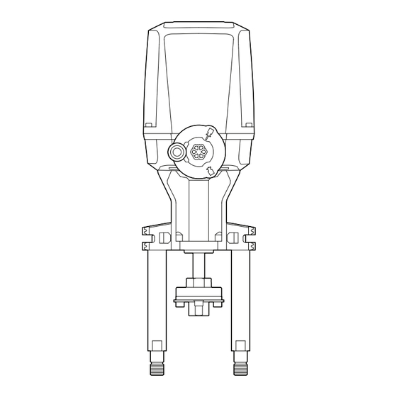
AEL8 Series Electric actuator
1.
Safety information
2.
General product
information
3.
Installation
4.
Electrical connections
5.
Actuator accessories and
spares
6.
Commissioning
7.
Maintenance
8
Declaration of Conformity
IM-P714-02
CTLS Issue 1
© Copyright 2023
1
Printed in GB
Advertisement
Table of Contents

Related Manuals for Spirax Sarco AEL8 Series


Summary of Contents for Spirax Sarco AEL8 Series
- Page 1 AEL8 Series Electric Linear Actuators Installation and Maintenance Instructions Safety information General product information Installation Electrical connections Actuator accessories and spares Commissioning Maintenance Declaration of Conformity AEL8 Series Electric actuator © Copyright 2023 IM-P714-02 CTLS Issue 1 Printed in GB...
-
Page 2: Safety Information
The requirements for the disconnecting device are specified in IEC 60947-1 and IEC 60947- 3 or equivalent. viii) The actuator must not be located in such a way that the disconnecting device is made difficult to operate. AEL8 Series Electric actuator IM-P714-02 CTLS Issue 1... -
Page 3: Intended Use
Determine the correct installation situation. iv) Spirax Sarco products are not intended to withstand external stresses that may be induced by any system to which they are fitted. It is the responsibility of the installer to consider these stresses and take adequate precautions to minimise them. -
Page 4: Pressure Systems
1.11 Tools and consumables Before starting work ensure that you have suitable tools and/or consumables available. Use only genuine Spirax Sarco replacement parts. 1.12 Protective clothing Consider whether you and/or others in the vicinity require any protective clothing to protect against the hazards of, for example, chemicals, high/low temperature, radiation, noise, falling objects, and dangers to eyes and face. -
Page 5: Residual Hazards
Customers and stockists are reminded that under EC Health, Safety and Environment Law, when returning products to Spirax Sarco they must provide information on any hazards and the precautions to be taken due to contamination residues or mechanical damage which may present a health, safety or environmental risk. -
Page 6: All Rights Reserved
Work(s) may not be used, sold, licensed, transferred, copied or reproduced in whole or in part or in any manner or form other than as expressly granted here without the prior written consent of Spirax-Sarco Limited. AEL8 Series Electric actuator IM-P714-02 CTLS Issue 1... -
Page 7: General Product Information
2. General product information 2.1 Introduction The AEL8 series electric linear actuators are only suitable for the use on Spirax Sarco group valves. Refer to TI-P714-01 for product compatibility and linkage requirements. The AEL8 Series actuators must not be used for any other purpose. Actuators will normally be supplied fitted to the control valve. When supplied separately, ensure the actuator selected is capable of providing the force necessary to close the two-port or three-port control valve against the expected differential pressure. - Page 8 2.0+ mm/s 90….264 Vac wide range input Supply voltage 24 Vac / 24 Vdc Control signal Modulating (0)4-20mA / 0(2)-10V Positioner None Failure mode Super-Capacitor Non-Retrofit option None Options I/O Module EasiHeat M12 AEL8 Series Electric actuator IM-P714-02 CTLS Issue 1...
-
Page 9: Operating Principle
2.3 Operating principle The AEL8 Series is a range of linear electric actuators of various voltages and thrusts suitable for the modulation of Spirax Sarco Group valves by means of modulating signal. Independent of the control method, the actuators typically uses two electro-mechanical force dependent (torque) switches to determine the end position of the actuator stroke in both directions and stop the actuator motor i.e. -
Page 10: Installation
3. Installation Before considering installation of an AEL8 Series actuator please read to Section 1 "Safety Information" on page 2. Installation awareness Lifting and fitting of actuators increases the risk of personal injury Mains connection and commissioning of the AEL8 Series actuator requires specialist knowledge of electrical circuits and systems, and the inherent dangers. - Page 11 Releasing the pressure on the hand wheel with a light pull will disengage the hand wheel clutch from the actuator gearbox, and the hand wheel will no longer be illuminated blue. The second function of the actuator hand wheel is as a diagnostic tool See Section 6.3 for details. AEL8 Series Electric actuator IM-P714-02 CTLS Issue 1...
- Page 12 The operator is responsible for ensuring that safe systems of operation and practice are implemented and maintained. Only competent persons must be allowed to couple the AEL8 Series actuator to a valve, and these persons must be familiar with, and comply with the applicable health and safety...
- Page 13 Couple the adapter locking plate Tighten the pillar nuts to 30 Nm Tighten the 4 valve adaptor screws to 8 Nm Tighten the thread lock nut to 15 Nm Fig 3. Thread engagement AEL8 Series Electric actuator IM-P714-02 CTLS Issue 1...
- Page 14 AEL82 2.0 kN AEL83 4.5 kN AEL84 6.0 kN EL5971 Integral 19 mm AEL85 8.0 kN AEL86 12.0 kN AEL87 15.0 kN Included in the standard scope of supply AEL82 to AEL85 AEL8 Series Electric actuator IM-P714-02 CTLS Issue 1...
- Page 15 AEL86 12.0 kN EL5974 M18 x 1.5 28 mm AEL8Q125 AEL87 15.0 kN Included in the standard scope of supply AEL82 to AEL85 Adapter must be ordered separately Spacer 3570003 also required AEL8 Series Electric actuator IM-P714-02 CTLS Issue 1...
- Page 16 2-6 kN actuators. Ensure that the power supply is correctly fused for the maximum expected load. Details of the requirements for each AEL8 Series actuator can be found in Tables on pages 17 and 18. AEL8 Series Electric actuator...
- Page 17 0.26 4.5 kN AEL83231PXX 0.49 AEL83231PSX 0.49 4.5 mm/s AEL83231PXO AEL83231PSO 0.49 AEL84221PXX AEL84221PSX 0.26 1.2 mm/s AEL84221PXO AEL84221PSO 0.26 6 kN AEL84231PXX 0.49 AEL84231PSX 0.49 3.6 mm/s AEL84231PXO 0.49 AEL84231PSO 0.49 AEL8 Series Electric actuator IM-P714-02 CTLS Issue 1...
- Page 18 1.6 mm/s AEL82223PSO AEL82223PXE AEL83223PXX AEL83223PSX 1.6 mm/s AEL83223PXO AEL83223PSO AEL83233PXX 4.5 kN AEL83233PSX AEL83233PXO 4.5 mm/s AEL83233PSO AEL83233PXE AEL84223PXX AEL84223PSX 1.2 mm/s AEL84223PSX AEL84223PXO 6 kN AEL84233PXX AEL84233PSX 3.6 mm/s AEL84233PXO AEL84233PSO AEL8 Series Electric actuator IM-P714-02 CTLS Issue 1...
-
Page 19: Making The Electrical Connection
4.1 Removing the actuator cover The AEL8 Series actuator cover is secured to the actuator housing by 4-off M6 socket cap-head screws. Each screw is held into the actuator cover with an 'O' ring to prevent loss. Once all screws are loosened, the actuator cover can be removed without interference. -
Page 20: Electrical Connection
Options 51 53 46 59 60 57 58 56 61 54 12 15 18 45 Power Power 24 Vac/dc 24 - 230 Vac/dc supply supply Fig 4. AEL8 Terminal diagram 100-240 Vac AEL8 Series Electric actuator IM-P714-02 CTLS Issue 1... - Page 21 Options Position feedback I/O Module Heater ▲▼ ▲▼ ▲ ▼ (NO) (NO) (NO) AEL8 Series Electric actuator IM-P714-02 CTLS Issue 1...
- Page 22 5.1 Actuator accessory safety information Caution Before commencement of any work to inspect, install, commission, remove or modify any of the AEL8 Series actuator accessories, please read to Section 1 "Safety Information" and Section 4.1 "Electrical Connection Safety Considerations". 5.2 Actuator accessory selection To select the correct accessories for each actuator, refer to Table 1.
- Page 23 0(2)-10V or (0)4-20mA control input Position feedback – automatically corresponds to input signal type (V or mA) AEL8 series actuators are only available with the Positioner Electronics Card installed as standard. This is to ensure accurate setpoint control at the elevated spindle speeds.
- Page 24 Connect wiring harness as indicated in Figure 5 (note: there is a locating nose on the wiring harness to ensure correct orientation, this is on the same side as the red wire). Positioner electrics card I/O module Fig. 5 PEL Orientation AEL8 Series Electric actuator IM-P714-02 CTLS Issue 1...
- Page 25 5.4 I/O Module The AEL8 series actuator can be equipped with an I/O module that provides: Normally Open (NO) VFC for end position indication Automatically sets at limitation of the valve during the auto-stroke procedure Diagnostic Fault Relay Normally Open (NO) VFC to provide indication of actuator fault...
-
Page 26: Anti-Condensation Heater
The anti-condensation heater is used as protection against the formation of condensation within the actuator cover in the case of: Strongly varying ambient temperatures High air humidity Outdoor application Fig. 6 I/O Module orientation AEL8 Series Electric actuator IM-P714-02 CTLS Issue 1... - Page 27 Information" and Section 4.1 "Electrical Connection Safety Considerations". Warning The anti-condensation heater can become very hot and easily burn. Care should be taken, gloves worn and the heater allowed sufficient time to cool before handling. AEL8 Series Electric actuator IM-P714-02 CTLS Issue 1...
-
Page 28: Anti-Condensation Heater Installation
Carefully align the anti-condensation heater as indicated in Figure 7 (Anti-Condensation Heater Orientation) and screw to the actuator baseplate with the screws provides (Max. 2Nm) Connect wires as indicated in Figure 4. Fig. 7 I/O Heater Orientation AEL8 Series Electric actuator IM-P714-02 CTLS Issue 1... - Page 29 " S afet y I nf o r m at i o n" a n d S e c t i o n 4.1 " El e c t r i c a l C o nn e c t i o n S afet y Considerations". Warning Mains connection and commissioning of the AEL8 Series actuator requires specialist knowledge of electrical circuits and systems, and the inherent dangers. A working knowledge of linear actuators is also required.
- Page 30 The positioner card is fitted with a series of DIP switches that can be used to configure: Input signal Feedback signal Direction of action Failure mode (loss of control signal only) Seating (commissioning) function Note For split range applications, please contact Spirax Sarco. AEL8 Series Electric actuator IM-P714-02 CTLS Issue 1...
- Page 31 Switchover MANUAL/AUTO Light emitting diodes (LEDs) Orange Green Blue L_Power Green LED showing PCB is powered DIP switches DIP switch row S1 DIP switch row S2 PROG AUTO Fig. 7 Positioner Electronics Card AEL8 Series Electric actuator IM-P714-02 CTLS Issue 1...
- Page 32 See Table on page 33 S1.5 S1.4 Reduced force Off* S1.3 0% position 4-20 mA / 2-10V 0-20 mA / 0-10V S1.2 Reversing signal 0% CLOSE 0% OPEN S1.1 Not in use AEL8 Series Electric actuator IM-P714-02 CTLS Issue 1...
- Page 33 S1.7 0% Position Close Open Stay in place End position configuration (seating) In Case of Input Signal Interuption S1.8 S1.7 Limit / Limit Thrust / Limit Limit / Thrust Thrust / Thrust AEL8 Series Electric actuator IM-P714-02 CTLS Issue 1...
- Page 34 Not in Use S2.1 Calibration of travel Off* Position in case of power supply interuption In Case of Input Signal Interuption S2.5 S2.6 Setpoint Off* Off* Close Open Stay in place * Default position AEL8 Series Electric actuator IM-P714-02 CTLS Issue 1...
- Page 35 Set S2.8 to "OFF" Illuminated Colour of handwheel Status handwheel – GREEN Ready for operation Actuator status BLUE Manual operation (handwheel engaged) ORANGE Warning (e.g. actuator operating at 50% speed) Fault AEL8 Series Electric actuator IM-P714-02 CTLS Issue 1...
- Page 36 LEDs on the I/O Module indicate when the Normally Open contacts are operating at stroke limits. 6.6 Commissioning of anti-condensation Heater Once installed and connected in accordance with Section 5.5.1, the Anti-Condensation Heater does not require to be commissioned independently. AEL8 Series Electric actuator IM-P714-02 CTLS Issue 1...
- Page 37 DCS system or a unique power supply. Caution The AEL8 series actuator is NOT a designated “Safety Device” and it must NOT be used as a single point of failure or protection. The actuator can however be configured as part of a safe system whereby it can be modulated to a safe position for the process.
-
Page 38: Maintenance Safety Information
Mains connection and maintenance of the AEL8 Series actuator or control valve requires specialist knowledge of electrical circuits and systems, and the inherent dangers. A working knowledge of linear actuators and control valves is also required. - Page 39 The following parts can be replaced in the event of a break-down. Please refer to the relevant Section of this document for details: I/O module Positioner electronics card Anti-condensation heater Elastomer sealing elements can be subject to deterioration and should be inspected at regular intervals and replaced if necessary. AEL8 Series Electric actuator IM-P714-02 CTLS Issue 1...
- Page 40 - actuator stop until temperature = Max.T - 20k Power supply low No movement of actuator to CLOSE No movement of actuator to OPEN Actuator out of limits LED not illuminated Continuous light Flashing Quick flashing AEL8 Series Electric actuator IM-P714-02 CTLS Issue 1...
-
Page 41: Removing The Actuator From The Valve
The AEL8 Series actuator should not be repaired in the field. In the rare event that the AEL8 Series actuator should need to be repaired, the actuator must be returned to the factory with a full field failure report. -
Page 42: Problem Solving
Positioner Electronic Card incorrectly commissioned Position override in operation Failure mode set to a position other than 100% Poor PID set-up "Actuator moving continuously Oversized control valve (hunting)" Positioner override function activated frequently (hi-limit) AEL8 Series Electric actuator IM-P714-02 CTLS Issue 1... -
Page 43: Declaration Of Conformity
Additional information: Signed for and on behalf of: Spirax Sarco Ltd, (signature): (name, function): N Morris Compliance Manager, Steam Business Development Engineering (place and date of issue): Cheltenham 2023-06-30 GNP252-CE-C issue 1 AEL8 Series Electric actuator IM-P714-02 CTLS Issue 1... - Page 44 Signed for and on behalf of: Spirax Sarco Ltd, (signature): (name, function): N Morris Compliance Manager Steam Business Development Engineering (place and date of issue): Cheltenham 30 June 2023 GNP252-UK-C issue 1 Page 1 of 1 AEL8 Series Electric actuator IM-P714-02 CTLS Issue 1...
Need help?
Do you have a question about the AEL8 Series and is the answer not in the manual?
Questions and answers