Advertisement
Advertisement
Table of Contents

Summary of Contents for Spirax Sarco SX75 Series
- Page 1 3231350/3 Issue 3 SX75 Series Process Controller Installation and Maintenance Instructions Printed in the UK Copyright 2006...
-
Page 2: Table Of Contents
GENERAL INDEX 1. SAFETY INFORMATION ........page 1 PRODUCT OVERVIEW 2. FUNCTIONS OF KEYS AND DISPLAYS ... page 3 3. DIMENSIONS INSTALLATION ......page 6 4. ELECTRICAL WIRING ........page 7 5. PASSWORD PROTECTION ......page 15 6. PROGRAMMING INSTUCTIONS FUNCTIONS MENU CONFIGURATION SETTING OF PARAMETERS (see enclosed leaflet) 7. -
Page 3: Safety Information
1. SAFETY INFORMATION All personnel using this product must carefully read this manual prior to operation. Your attention is drawn to Safety Information Leaflet IM-GCM-10. If these controllers are handled improperly or not used as specified, the result may: cause danger to the life and limb of the user or a third party. damage to the controller and other items belonging to the owner. -
Page 4: Product Overview
1.2 SAFETY REQUIREMENTS AND ELECTROMAGNETIC COMPATIBILITY NOTES This product is CE marked. It conforms to the council directive 89/336/EEC and the directive 92/31EEC, which modifies the directive 89/336/EEC (Electromagnetic Compatibility) by meeting the standards EN50081-2 (Industrial emission) and EN50082- 2 (Industrial immunity). -
Page 5: Functions Of Keys And Displays
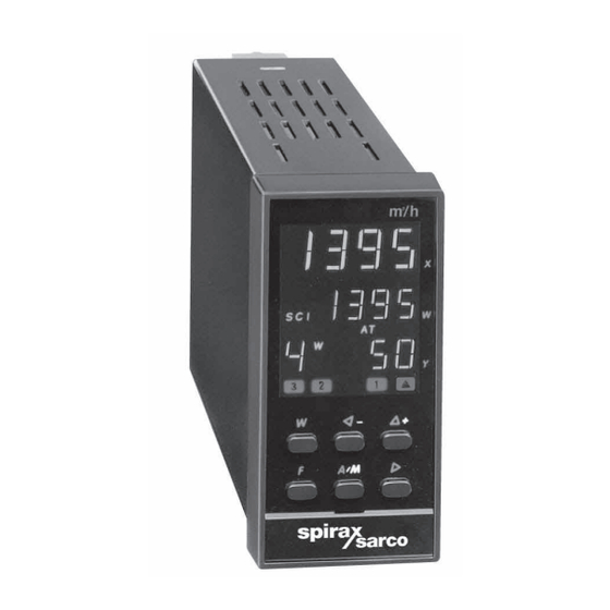
2. FUNCTION OF KEYS AND DISPLAYS NUMERIC INDICATORS X, W, Y, N° Measured Value X The value of measure X is expressed in engineering units. (green) 8888 ____ If value over range 8888 ---- If value under range 275. 8 - In parameters: displays parameter values - In configuration: displays the values of EFGH configuration code (see enclosed leaflet) - Page 6 2. FUNCTION OF KEYS AND DISPLAYS...
- Page 7 2. FUNCTION OF KEYS AND DISPLAYS...
-
Page 8: Dimensions Installation
3. DIMENSIONS - INSTALLATION... -
Page 9: Electrical Wiring
4. ELECTRICAL WIRING A T erminal boar d B Freeing the terminals All screw terminals M3.5 Lift the plate to free Location pin the location pin Wiring protection plate Rotate downwards Plate screw C Wirring connections D Protecting the terminal board With eyelet Cable wires... - Page 10 4. ELECTRICAL WIRING...
- Page 11 4. ELECTRICAL WIRING...
- Page 12 4. ELECTRICAL WIRING Schema di collegamento 3 • Remote Set point input Rin = 30 Ω per mA In current 4..20 mA Rin = 330 KΩ per V In voltage 0..10Vdc NOT galvanically Remote Set point mA, Volt isolated 4 • Logic inputs External contacts Closing of contacts C1, C2, C3, for two seconds permits the selection...
- Page 13 4. ELECTRICAL WIRING...
- Page 14 4. ELECTRICAL WIRING...
- Page 15 4. ELECTRICAL WIRING...
- Page 16 4. ELECTRICAL WIRING...
-
Page 17: Password Protection
5. PASSWORD PROTECTION... -
Page 18: Functions Menu
6•PROGRAMMING INSTRUCTIONS • SX75 SERIES CONTROLLERS FUNCTIONS MENU PARAMETERS GROUP 3 - ADVANCED FUNCTIONS GROUP 1 - SETPOINTS GROUP 2 - CONTROL FUNCTIONS DISPLAY pAss Enter correct during normal From configuration Measured Value Password 1111 Press F for operation process 275. -
Page 19: Changing Numeric Values
7 • OPERATING INSTRUCTIONS • SX75 SERIES CONTROLLERS FUNCTIONS MENU SET POINT Modify Set Point Procedure to recall a Set point from memory Local Remote Remote Set point status DISPLAY During normal operation During normal operation During normal operation Serial... - Page 20 8. EVENT / ALARM OUTPUTS Y2 AND Y3...
- Page 21 8. EVENT / ALARM OUTPUTS Y2 AND Y3...
-
Page 22: Operating Mode
9. OPERATING MODE... -
Page 23: Technical Data
10. TECHNICAL DATA 0.2% ± 1 digit (for input with RTD Pt100 and thermocouples) Accuracy (a25°C amb.) 0.1% ± 1 digit (for input in current and voltage) RTD Pt100 Pt100Ω @ 0°C, (IEC 751) Thermocouples J-K-S-R (IEC 584), L (DIN 43710) With Input "X"... - Page 24 10. TECHNICAL DATA...


Need help?
Do you have a question about the SX75 Series and is the answer not in the manual?
Questions and answers