Advertisement
Table of Contents
1 • INSTALLATION
• Dimensions and cut-out; panel mounting
48
108 96
92
113
10
96
108 96
92
113
10
Panel mounting:
To fix the instrument, insert the brackets provided into the seats on either side of the
case. To mount two or more instruments side by side, respect the cut-out dimensions
shown in the drawing. In order to get the IP65 protection, take the instruments out from
its case and apply the supplied gasket of the front edge of the case itself using some
adhesive. The replace the instruments inside the case.
CE MARKING: EMC conformity (electromagnetic compatibility) with EEC Directive
89/336/CEE with reference to the generic Standard EN50082-2 (immunity in industrial
environments) and EN50081-1 (emission in residential environments). BT (low voltage)
conformity respecting the Directive 73/23/CEE modified by the Directive 93/68.
Limitations: the 1800V model conforms to EN55011 standard for radiated emissions in
industrial environment.
MAINTENANCE: Repairs must be carried out only by trained and specialised
personnel. Remove the power to the instrument before accessing the internal parts.
DO NOT clean the case with solvent (trichlorethylene, petrol, etc.). The use of such
solvents can have adverse effects on the mechanical reliability of the instrument. To
clean the plastic case please use a clean cloth with ethilic alcohol or water.
SERVICE: SPIRAX-SARCO has a service department. The guarantee excludes defects
caused by usage that does not conform to the instructions.
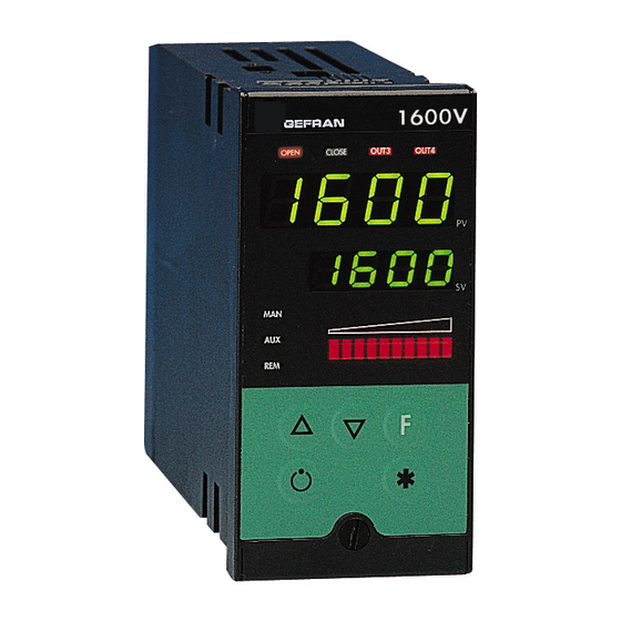
1600V / 1800V
CONTROLLER FOR VALVE
70
115
44,5
115
115
92
To ensure a correct
installation, heed the
warnings in the
manual
USERS' MANUAL
SOFTWARE VERSION 3.0x
code 80086 / Edition 0.5 - 01/2001
ISO 9001
Tel. +39 02.92119511 - Fax +39 02.9240321
2 • TECHNICAL SPECIFICATIONS
Display
Keys
Accuracy
Main input
Thermocouples
Cold junction error
RTD type (scale configurable within
indicated range, with or without decimal point
PTC type (on request)
Max line resistance for RTD
Safety
°C / °F selection
Linear scale ranges
Control terms
pb / dt / di
Control actions
Control outputs
Cycle time
Main output type
Softstart
Maximum power limit heat / cool
Fault power setting
Automatic blanking
Configurable alarms
Alarm masking
Type of relay contact
Logic output for static relay
(option) remote set-point or
Ammeter input
!
Feed-back input
Valve position from potentiometer
CT scale range
Transmitter power (optional)
Analogue retransmission signal
(optional)
Logic inputs (optional)
Serial interface (optional)
Baude rate
Protocol
Power supply (switching type)
Faceplate protection
Working / Storage temperature range
Relative humidity
Installation
Weight
The EMC conformity has been tested with the following connections
FUNCTION
Power supply cable
Relais output cable
Digital communication wires
C.T. connection cable
TC input
Pt100 input
1
SPIRAX SARCO Srl
Via Pasubio, 8
20063 Cernusco sul Naviglio
2 x 4 digits green of height 10 and 7mm (1600V),
20 and 13mm (1800V)
5 mechanical keys (*, Man/Auto, INC, DEC, F)
0.2% full scale a 25°C ambient temperature
TC, RTD (Pt100 - JPT100), PTC,
60mV, Ri ≥ 1MΩ, 10V, Ri ≥ 10KΩ, 20mA, Ri = 50Ω
IEC 584-1 (J, K, R, S, T, B, E, N, Ni-Ni18Mo, L NiCr-CuNi)
0,1° / °C
DIN 43760 (Pt100, JPT100)
990Ω, 25°C
20Ω
detection of short- or open-circuit probe,
LBA alarm, HB alarm
faceplate configurable
-1999 to 9999 with configurable decimal point position
PID, Auto-tune, on-off
0.0 ... 999.9% / 0.00 ... 99.99min / 0.00 ... 99.99min
Heat / Cool
on / off, pwm, Apri / Chiudi
0.1 ... 200 sec
Relay, Logic, Continuous (optional)
0.0 ... 500.0 min
0.0 ... 100.0 %
-100.0 ... 100.0 %
Optional exclusion, displays PV value
3 configurable alarms of type: high, low, deviation,
absolute or relative, LBA, HB
- exclusion during warm up
- latching reset from faceplate or external contact
NO (NC), 5A, 250V, cosϕ = 1
11Vdc, Rout = 220Ω (6V/20mA)
0 ... 10V, 2 ... 10V, Ri ≥ 1MΩ
0 ... 20mA, 4 ... 20mA, Ri = 5Ω
Potentiometer > 500Ω,
CT 50mAac, 50/60Hz, Ri = 1,5Ω,
isolation 1500V
configurable from 0, ... , 100.0A
filtered 10 / 24Vdc, max 30mA
short-circuit protection, isolation 1500V
10V / 20mA, isolation 1500V
24V NPN, 4.5mA; 24V PNP, 3.6mA
isolation 1500V
CL; RS422/485; RS232; isolation 1500V
1200 ... 19200
GEFRAN / MODBUS
(std) 100 ... 240Vac/dc ±10%; 50/60Hz, 12VA max
(opz.) 20...27Vac/dc ±10%; 50/60Hz, 12VA max
IP65
0...50°C / -20...70°C
20 ... 85% Ur non condensing
Panel, plug-in from the front
400g (1600V); 600g (1800V) in complete version
CABLE TYPE
LENGTH
1 mm
2
1 mt
1 mm
2
3,5 mt
0,35 mm
2
3,5 mt
1,5 mm
2
3,5 mt
0,8 mm
2
compensated
5 mt
1 mm
2
3 mt
Advertisement
Table of Contents

Related Manuals for Spirax Sarco 1600V


Summary of Contents for Spirax Sarco 1600V
- Page 1 20063 Cernusco sul Naviglio ISO 9001 Tel. +39 02.92119511 - Fax +39 02.9240321 1 • INSTALLATION 2 • TECHNICAL SPECIFICATIONS 2 x 4 digits green of height 10 and 7mm (1600V), Display 20 and 13mm (1800V) • Dimensions and cut-out; panel mounting Keys...
-
Page 2: Faceplate Description
3 • FACEPLATE DESCRIPTION Indication of output states: Function indicator OUT 1 (Open); OUT 2 (Close); Indicates modes of operation OUT 3 (AL 1); OUT 4 (HB) MAN = OFF (Automatic control) MAN = ON (Manual control) PV Display: Indication of process variable AUX = OFF (IN1 = OFF - Local setpoint 1) Error Indication: LO, HI, Sbr, Err AUX = ON (IN1 = ON - Local setpoint 2) -
Page 3: Instrument Layout
Instrument layout OutW/ serial Board Relay state at power ON S14 (S3) close S2 relay Out2 Configuartion and Calibration enable S3 relay Out3 S4 close = Calibration enable Relay state at powerr A = OFF S2 relay Out4 B = ON Power Supply enable CPU Board A = OFF... -
Page 4: Info Display
• Info display -999 ... 999 Information INFO Manual reset scale points display prot Software protection code Serial (ODE p. r st communication Reset power -100.0 ... 100.0% code 0 No Error er. n r Self 1 Lo diagnostic 2 Hi updt error code Software... - Page 5 • Ser Serial communications bavd Baudrate Instrument identification code when (ode connected in serial line (if enabled) bAud Baudrate CENCAL Interface MODBUS Interface 0 ... 9999 [see “hrd.1” in Hrd] 1200 CL / 485 / 232 2400 485 / 232 4800 485 / 232 Digital...
- Page 6 Digital filter on auxiliary filt flt. 2 Digital filter on main input 0.0 ... 20.0 sec input (if enabled) 0.0 ... 20.0 sec [see “hrd.1” in Hrd] Minimum limit of the fild lo. 5 2 Digital filter on display auxiliary input scale min...max input range 0 ...
- Page 7 Out W1 an. o . 1 Allocation of rl. o . 1 Allocate signal or reference value: reference signal PV, SP, SP-PROG, DEV+, DEV-, IN.AUX, HEAT, to the Out1 COOL, AL1, AL2, AL3, serial line value output: HEAT, COOL, AL1, AL2, AL3, An.o.1, An.o.2 rL.o.1, rL.o.2, rL.o.3, rL.o.4 input repetition...
- Page 8 • Hrd SEnS Probe type for main input Selection of the Hardware configuration Thermocouple (TC) sens input type for the Resistance Thermometer (RTD) main input Thermistor (PTC) hrd.1 Auxiliary Logic Logic Serial Voltage 0...50mV / 10...50mV analogue input 1 input 2 interface Current 0...20mA / 4...20mA Installation of...
- Page 9 bArG Heat Function of the "MAN": M/A, L/R, ATUN LEDs, IN1, IN2 repetition, led. 1 barg Cool Bargraph event programmer, serial port enabled, errors present Heat + Cool function LEd.1 (MAN), LEd.2 (AUX), LEd.3 (REM) Aux. input (V2 valve position) LEd.x Function led.
-
Page 10: Motorized Valve Control
6 • MOTORIZED VALVE CONTROL In a control process the control valve has to adjust the liquid fuel flow rate (often corresponding to the thermal energy of the process) depending on the signal coming from the controller. To this purpose , the valve is equipped with an actuator capable to modify its opening value, forcing the resistance produced by the fluid flowing inside it. - Page 11 Every action updates the presumed position of a virtual potentiometer calculated on the basis of the declared actuator time. In this way, there is always a presumed position of the valve that is compared with the controller output. Once the valve reaches a fully opened or fully closed position as calculated by the virtual potentiometer, the controller will supply a series of pulses in the same direction in equal intervals of time with the length of the minimum pulse in order to ensure that the actual end stop is reached.
- Page 12 10 • ALARMS Absolute alarm Symmetrical absolute alarm AL1 + [ Hyst1 ] AL2 + Hyst2 AL1 + Hyst1 AL1 - [ Hyst1 ] tempo time alarm 1 reverse direct alarm 2 For AL1 = Lo absolute alarm with positive Hysteresis Hyst1, AL1 t = 1 For AL1 = symmetrical Lo absolute alarm with Hysteresis Hyst1, AL1 t = 5 (*) = OFF if disabled on power-up For AL1 = symmetrical Hi absolute alarm with Hysteresis Hyst1, AL1 t = 4...
-
Page 13: Manual Tuning
12 • NOTES ON THE CONTROL ACTIONS Proportional Action: the term whose contribution to the output is proportional to the deviation of the input (the deviation is the difference between the measured variable and the set-point). Derivative Action: the term whose contribution to the output is proportional to the rate of variation of the input signal deviation. Integral Action: the term whose contribution to the output is proportional to the integral with time of the input signal deviation. -
Page 14: Self-Tuning
15 • SELF-TUNING The function works very well for single output systems (heating or cooling). The self-tuning action has the scope of calculating the optimum values for the control parameters during the start up of the process. The variable (for example the temperature) must be that assumed at zero power (ambient temperature). The controller supplies maximum output power until a point below the set-point is reached. - Page 15 18 • MAIN INPUT CORRECTION FUNCTION It allows a custom correction of the main input reading throught the setting of four values: A1, B1, A2, B2. This function can be enabled selecting “Sens” +8 code (menu “Hrd”). Example: Sens = 1+8 = 9 for RTD sensor with input correction. If this function is applied to linear scales (50mv, 10V, 20mA, Pot), it is possible to reverse the scale.
- Page 16 ORDER CODE POWER SUPPLY MODEL 20...27Vac/dc ±10% 100...240Vac/dc ±10% 1600 V 1600 V 1800 V 1800 V DIGITAL COMMUNICATIONS None OUTPUTS 1,2,3,4 (R/D) Current Loop Out1 (R) + Out2 (R) + Out3 (R) RRR0* RS 485 Out1 (R) + Out2 (R) + Out3 (R) + RS 232C RRRR Out4 (R)
Need help?
Do you have a question about the 1600V and is the answer not in the manual?
Questions and answers