Table of Contents
Advertisement
4025251/9
LC2250
Level Controller
Installation and Maintenance Instructions
LC2250
%
AL
OK
IM-P402-130
EMM Issue 9
1.
Safety information
2.
User instructions and
delivery information
3.
System overview
4.
Mechanical installation
5.
Electrical installation
6.
Commissioning
- Quick set-up
- Full
7.
Communications
8.
Maintenance
9. Fault finding
10. Technical information
- Default settings
11. Appendix
- Data registers
12. Menu map
© Copyright 2017
Printed in GB
Commissioning password
Current legislation states that in order to prevent tampering and potentially hazardous
programming errors, access to the pass codes required to enter commissioning mode
should only be available to qualified and trained personnel.
Enter commissioning
To enter the commissioning mode, press and hold the
The display will show the pass code '888'. Enter the pass code '745'. This is fixed and cannot
be changed.
If an incorrect pass code is entered, the display will return to showing the current valve / pump
status – run mode.
If the correct pass code is entered, the display will show the main menu structure. Select
'End' to leave the menu.
Once in the commissioning mode press the
-
to scroll through the menus.
-
to increase digits when in a menu.
Press the
button to enter a menu choice (select a parameter or digit) and shift right, onto
OK
the next digit.
This page MUST be removed after
commissioning and kept in a safe,
access controlled location.
button for 5 seconds.
OK
button:
IM-P402-130 EMM Issue 9
Advertisement
Table of Contents

Related Manuals for Spirax Sarco LC2250


Summary of Contents for Spirax Sarco LC2250
- Page 1 Current legislation states that in order to prevent tampering and potentially hazardous programming errors, access to the pass codes required to enter commissioning mode should only be available to qualified and trained personnel. LC2250 Enter commissioning Level Controller To enter the commissioning mode, press and hold the button for 5 seconds.
- Page 2 This product is suitable for Class A Environments (e.g. industrial). A fully detailed EMC assessment has been made and has the reference number: UK Supply BH LC2250 2012. The product may be exposed to interference above the limits of heavy Industrial Immunity if: The product or its wiring is located near a radio transmitter.
- Page 3 Static precautions (ESD) Static precautions must be observed at all times to avoid damage to the product. Level control and level limiting products in steam boilers Products /systems must be selected, installed, operated, and tested in accordance with: Local or National standards and regulations. Guidance Notes, (Health and Safety Executive BG01 and INDG436 in GB).
- Page 4 Symbols Equipment protected throughout by double insulation or reinforced insulation. Functional earth (ground) terminal, to enable the product to function correctly. Not used to provide electrical safety. Clean earth / ground. Safety earth. Caution, risk of electric shock. Caution, risk of danger, refer to accompanying documentation. Optically isolated current source or sink.
-
Page 5: Intended Use
Determine the correct installation situation and direction of fluid flow. iv) Spirax Sarco products are not intended to withstand external stresses that may be induced by any system to which they are fitted. It is the responsibility of the installer to consider these stresses and take adequate precautions to minimise them. -
Page 6: Protective Clothing
1.9 Tools and consumables Before starting work ensure that you have suitable tools and / or consumables available. Use only genuine Spirax Sarco replacement parts. 1.10 Protective clothing Consider whether you and / or others in the vicinity require any protective clothing to protect against the hazards of, for example, chemicals, high / low temperature, radiation, noise, falling objects, and dangers to eyes and face. -
Page 7: Returning Products
1.16 Returning products Customers and stockists are reminded that under EC Health, Safety and Environment Law, when returning products to Spirax Sarco they must provide information on any hazards and the precautions to be taken due to contamination residues or mechanical damage which may present a health, safety or environmental risk. -
Page 8: All Rights Reserved
Spirax-Sarco Limited. 2.1 General description The LC2250 is a level controller for conductive liquids. It has two alarms that can be configured high or low. WARNING: The minimum conductivity when used with the LP20 / PA20 or PA420. -
Page 9: Using The Buttons
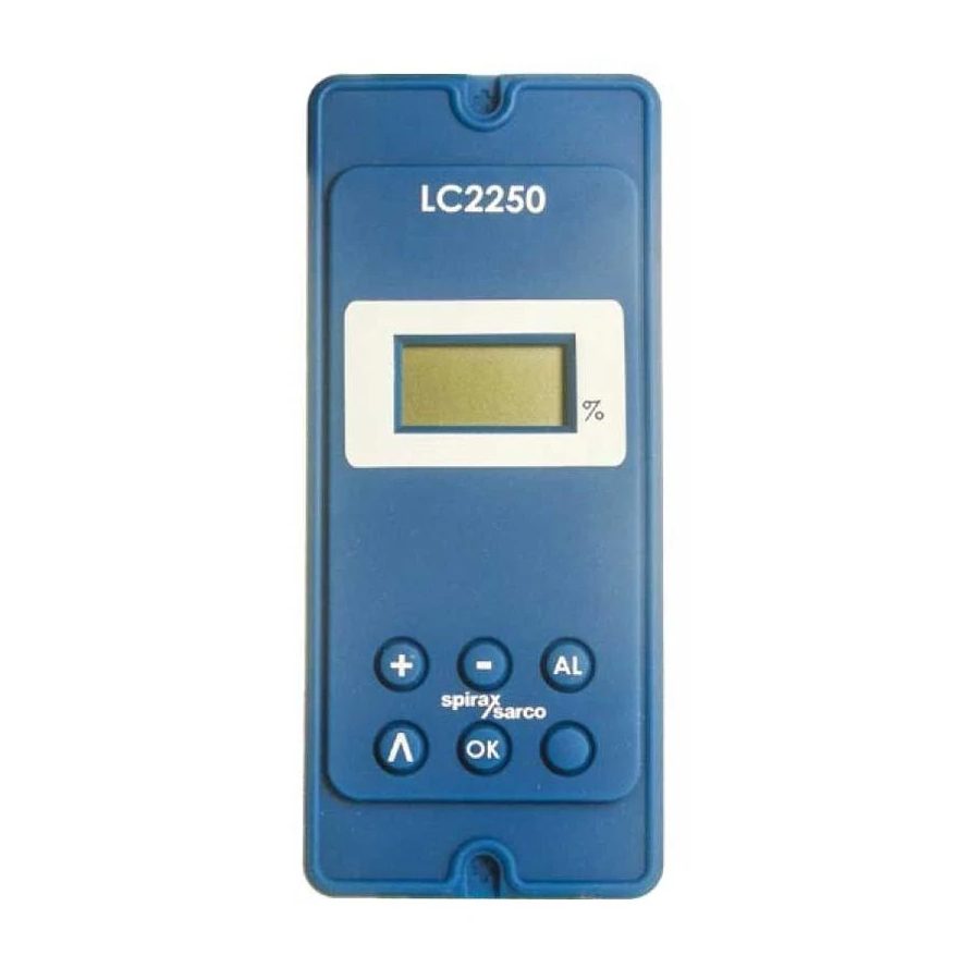
2.3 Using the buttons Use the button to: scroll through the menus. button is used to: enter the commissioning mode (press and hold for five seconds). enter the alarm reset passcode. button is used to: test the alarm relays. test the external circuits. 2.4 LCD display The LCD display shows what the system is doing. -
Page 10: Proportional Control
Alarm ALarm. This warns of a level alarm condition. Level alarm if occuring or has been latched. Testing the alarm relays and circuit. To do this press the 'AL' button, either in run or commissioning mode. Note: In commissioning mode only AL is displayed. The level signal is out of range (OOr). - Page 11 Each carton should be unpacked carefully and its contents checked for damage. If it is found that some items have been damaged or are missing, notify Spirax Sarco immediately and provide full details. In addition, damage must be reported to the carrier with a request for their on-site inspection of the damaged item and its shipping carton.
-
Page 12: System Overview
The product can communicate via an infrared link between adjacent boiler house controllers (Spirax Sarco products only). It is designated as a slave unit only - see Section 7 - Communications. IM-P402-130 EMM Issue 9... -
Page 13: Mechanical Installation
4. Mechanical installation Note: Read the 'Safety information' in Section 1 before installing the product. The product must be installed in a suitable industrial control panel or fireproof enclosure to provide impact and environmental protection. A minimum of IP54 (EN 60529) or Type 3, 3S, 4, 4X, 6, 6P and 13 (UL50/NEMA 250) is required. - Page 14 4.3 Installation on a chassis plate: Drill holes in chassis plate as shown in Figure 2. Fit unit to chassis plate and secure with 2 screws, nuts and washers, using the slots provided at the top and bottom of the case. Warning: Do not drill the product case or use self-tapping screws.
- Page 15 Fig. 2 Ø 4.2 mm Ø 4.2 mm Chassis plate / panel - 10 mm cutout diagram 45 mm 112 mm 92 mm 22.5 10 mm Ø 4.2 mm Ø 4.2 mm 67 mm 120 mm 8 mm 112 mm 120 mm IM-P402-130 EMM Issue 9...
-
Page 16: Electrical Installation
5. Electrical installation Note: Before installing read the 'Safety Information' in Section 1. Warning: Isolate the mains supply before touching any of the wiring terminals as these may be wired to hazardous voltages. Use only the connectors supplied with the product, or spares obtained from Spirax-Sarco Limited. - Page 17 10. All external circuits must meet and maintain the requirements of double / reinforced installation as stated in IEC 60364 or equivalent. 11. Additional protection must be provided to prevent accessible parts (e.g. signal circuits) from becoming Hazardous Live if a wire or screw is accidentally loosened or freed. Ensure all wires are secured to at least one other wire from the same circuit.
- Page 18 5.2 Mains wiring notes: 1. Read Section 5.1 - 'General wiring notes', before attempting to wire the supply to the product. 2. The wiring connections are identified on the terminal plugs. 3. Fuses must be fitted in all live conductors. 4.
- Page 19 Alarm Input Norm 3 A fuse 22 21 20 Caution live Mains circuit terminals (view from the underside) Relays are shown in the Alarm 2 relay power off position Control relay Alarm 1 relay ac supply Modulating control 3 A fuses Norm Control valve electric fuse...
- Page 20 5.3 Signal wiring notes An earth current loop is created if a wire or screen is connected between two earth points that are at different potential (voltage). If the wiring diagram is followed correctly, the screen will only be connected to the earth at one end. The earth terminal is a functional earth rather than a protective earth.
- Page 21 5.5 Level input options The level output from a PA20 preamplifier and LP20 capacitance level probe can be 'daisy chained' to more than one instrument (See Figure 7). Level input(s) +24 V Another LC2250 LC2200 LT2010, LC2300 or LC2500 Building...
- Page 22 Each instrument must be capable of receiving a 1 - 6 Vdc signal. Only one of the instruments needs to provide a 24 V nominal supply. In Figure 7, the product is supplying the power for the capacitance probe. Level input(s) +24 V Vin Iin COM SCN 51 52...
- Page 23 5.6 Wiring diagram for UL version of PA20 For the PA20 preamplifier and the LP20 capacitance probe (see the PA20 and LP20 Installation and Maintenance Instructions). Level input(s) +24 V Vin Iin COM SCN 50 51 52 53 54 55 Connect to a clean local earth in the...
-
Page 24: General Information
/ digits (when flashing) Fig. 11 Display screen and keypad Please note that the LC2250 has no battery. The programmed settings are held in non-volatile memory (Flash) and are written to after changing a parameter and pressing the button. - Page 25 6.2 Manual test buttons Note: These buttons are not accessible if editing a parameter in commissioning mode. The product will return to the 'end' of the commissioning menu when these buttons are released. Alarm button In run mode or commissioning mode, this button can be used to test the alarm relays and the external circuits.
- Page 26 6.3.1 Commissioning - quick set-up This section allows the user to carry out the minimum commissioning necessary to operate the system for two typical applications. It accepts the defaults set in the factory, so will only work if the original default settings have not been altered.
-
Page 27: Main Menu Structure
6.4 Commissioning - Full Enter 'commissioning' as stated in Section 2, and follow the main menu structure to make the changes required. Warning: The minimum conductivity when used with the LP20 / PA20 or PA420 is 5 µS / cm or 5 ppm. 6.4.1 Main menu structure Input Select –... - Page 28 drive type – relay for Valve Motor Drive or rEtransmit for 4 - 20 mA. rel or rEt (only available when proportional control is selected). Drive ACtion – Inverts the output to the actuator, positioner or pump. Select In for fill control, e.g. boiler feedtank. Select Out for empty control, e.g.
- Page 29 Note: In the run mode, the end menu does not appear. It may be replaced by an error menu. See LCD display - Section 2.4. 100% Absolute maximum safe water level High alarm 85% Control band 20% Set point 50% (symmetrical about the set point) Low alarm 20% Absolute minimum...
- Page 30 6.5 Main menu commissioning notes 6.5.1 Lhi - Level Hi Calibrates the unit to 100% of the gauge glass. Set the water level in the boiler or tank to the top of the gauge glass. Press the button to select LhI. Press the button to enter the sub-menu.
-
Page 31: Maintenance
Boiler water level controls and level alarms, however, do require testing and inspection. General guidance is given in Health and Safety Executive Guidance Notes BG01 and INDG436. For specific instructions for the Spirax Sarco system please see separate literature. Cleaning instructions Use a cloth dampened with tap / de-ionised water or isopropyl alcohol. -
Page 32: Fault Finding
9. Fault finding WARNING: Before fault finding read the Safety information in Section 1 and the General wiring notes in Section 5.1. Please note that there are hazardous voltages present and only suitably qualified personnel should carry out fault finding. The product must be isolated from the mains supply before touching any of the wiring terminals. - Page 33 Symptom Action 1. Switch off the mains supply to the product. 2. Disconnect all signal wires. 3. Switch the mains supply on: If symptoms are still present, return the product for examination. 4. Replace each signal wire in turn until the fault occurs. 5.
-
Page 34: Operational Error Messages
9.3 Operational error messages Any operational errors that occur will be displayed in the run mode, on the alarms and errors screen. Error message Cause Action There has been a 1. Remove power from product. loss of power to 2. Check that all wiring is correct. the product during 3. -
Page 35: Technical Information
/ delivery documentation or on our web site: www.spiraxsarco.com 10.2 Returning faulty equipment Please return all items to your local Spirax Sarco representative. Please ensure all items are suitably packed for transit (preferably in the original cartons). Please provide the following information with any equipment being returned: 1. - Page 36 10.4 Environmental General Indoor use only Maximum altitude 2 000 m (6 562 ft) above sea level Ambient temperature limits 0 - 55 °C (32 - 131°F) 80% up to 31 °C (88°F) decreasing linearly to 50% Maximum relative humidity at 40 °C (104°F) Overvoltage category 2 (as supplied)
- Page 37 0.2 mm² (24 AWG) to 2.5 mm² (14 AWG) Stripping length 5 - 6 mm Caution: use only the connectors supplied by Spirax Sarco Ltd. Safety and Approvals may be compromised otherwise. Level probe and feedback cable / wires Type...
- Page 38 10.6 Input technical data Level voltage Minimum voltage 0 Vdc or 1 V (with OUTRANGE function selected) Maximum voltage 6 Vdc (absolute maximum = 7 Vdc) Input impedance 28 kΩ Accuracy 5% FSD over operating range Repeatability 2.5% FSD over operating range Resolution 14 bit (0.15 mV approx) Sample time...
- Page 39 10.7 Output technical data 24 Vdc supply Maximum voltage 26.4 Vdc Maximum current 25 mA Ripple voltage 10 mV @ 264 V, full load 4 - 20 mA Minimum current 0 mA Maximum current 20 mA Open circuit voltage (maximum) 19 Vdc Resolution 0.1% FSD Maximum output load...
- Page 40 10.8 Programming parameters / default settings The default settings in this table are used in the 'quick start' guide - See Section 6.3.1. InS - Input Select Ranges 1-6 or 4.20 Default Units Vdc or mA InF - Input Filter Ranges 2, 8 or 16 Default...
- Page 41 ALF - Alarm Filter - Applies to Alarm 1 and Alarm 2 Ranges OFF or ON Default ALL - Alarm Latch - Applies to Alarm 1 and Alarm 2 Ranges OFF or ON Default rEt - Retransmit Ranges 4 - 20 mA or 0 - 20 mA Default 4 - 20 mA dr - Drive...
- Page 42 11. Appendix - Data Registers Parameters and register data Register Level parameters 4 (Identity) Process variable (PV) - Water Level (%) Set point (SP) Control band (CB) Alarm 1 Alarm delay Alarm 2 The format of the register data is 16 bit integer, with the most significant byte transmitted first. 12.
- Page 43 Continued from page 42 0 - 100% Alarm level percentage 2 On (8 seconds delay) Alarm filter Alarm latch 4 - 20 mA Retransmit 0 - 20 mA Drive type IN (fill control) Drive action OUT (empty control) 0 - 100% Level high 0 - 100% Level low...
- Page 44 IM-P402-130 EMM Issue 9...
Need help?
Do you have a question about the LC2250 and is the answer not in the manual?
Questions and answers