Advertisement
Table of Contents
IM-P357-29
3579049/14
CTLS Issue 14
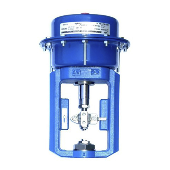
PN9000 Series
Pneumatic Actuators
Installation and Maintenance Instructions
PN9100
1. Safety information
PN9200
2. General product
information
PN9300
3. Installation
4. Commissioning
PN9400
5. Maintenance
6. Spare parts
© Copyright 2017
IM-P357-29
1
CTLS Issue 14
Printed in France
Advertisement
Table of Contents

Related Manuals for Spirax Sarco PN9120


Summary of Contents for Spirax Sarco PN9120
- Page 1 IM-P357-29 3579049/14 CTLS Issue 14 PN9000 Series Pneumatic Actuators Installation and Maintenance Instructions PN9100 1. Safety information PN9200 2. General product information PN9300 3. Installation 4. Commissioning PN9400 5. Maintenance 6. Spare parts © Copyright 2017 IM-P357-29 CTLS Issue 14 Printed in France...
- Page 2 IM-P357-29 CTLS Issue 14...
-
Page 3: Safety Information
Group 2 of the above mentioned Pressure Equipment Directive. The products’ use on other fluids may be possible but, if this is contemplated, Spirax Sarco should be contacted to confirm the suitability of the product for the application being considered. -
Page 4: Pressure Systems
1.9 Tools and consumables Before starting work ensure that you have suitable tools and / or consumables available. Use only genuine Spirax Sarco replacement parts. 1.10 Protective clothing Consider whether you and / or others in the vicinity require any protective clothing to protect against the hazards of, for example, chemicals, high / low temperature, radiation, noise, falling objects, and dangers to eyes and face. -
Page 5: Residual Hazards
1.16 Returning products Customers and stockists are reminded that under EC Health, Safety and Environment Law, when returning products to Spirax Sarco they must provide information on any hazards and the precautions to be taken due to contamination residues or mechanical damage which may present a health, safety or environmental risk. -
Page 6: General Product Information
2. General product information 2.1 General information The PN9000 series actuators are a compact range of linear actuators that are available in four sizes. This range of actuators comprise of four diaphragm sizes for matching the requirements of valves at various differential pressures. Each actuator has a mechanical travel indicator fitted and incorporates a fully-rolling diaphragm, except size 4, which provides good linearity over the operating stroke. -
Page 7: Spring Ranges
2.3 Spring ranges Actuator types Spring range Travel PN9120 0.2 to 1.0 bar 20 mm PN9120 0.4 to 1.2 bar 20 mm PN9125 0.4 to 2.0 bar 20 mm PN9126 1.0 to 2.0 bar 20 mm PN9123 2.0 to 4.0 bar... - Page 8 2.4 Materials - PN9100, PN9200 and PN9300 Part Material Yoke SG iron Upper diaphragm housing Carbon steel (plated) Diaphragm plate Aluminium Diaphragm Reinforced NBR Spring Spring steel Spindle Stainless steel Washer Carbon steel (plated) Spacer Carbon steel (plated) 'O' ring Viton Connector Stainless steel...
- Page 9 19 and 20 26 and 27 13 and 14 Fig. 1 PN9200E PN9000 Carbon steel (plated) Gr. 8.8 Socket head screw PNP9000 Stainless steel A2 - 70 PN9000S Stainless steel A2 - 70 Washer Carbon steel (plated) Screw Carbon steel (plated) Gr.
- Page 10 2.5 Materials - PN9400 Part Material Yoke SG iron Bearing and seal insert Carbon steel Bearing PTFE / steel composite Seal Polyurethane Gasket Reinforced graphite Housing lower Carbon steel Spindle Stainless steel Diaphragm protection plate Carbon steel Diaphragm Reinforced NBR Spacer Carbon steel Spring...
- Page 11 Fig. 2 PN9400E IM-P357-29 CTLS Issue 14...
- Page 12 2.5 Materials - PN9400 Part Material Adaptor Stainless steel Collar Stainless steel Clamp Stainless steel Scale Stainless steel Lock-nut Carbon steel Screw Carbon steel Carbon steel Screw Carbon steel Carbon steel Screw Carbon steel 'O' ring Viton Vent plug Brass Washer 'O' ring Carbon steel Intermediate plate...
- Page 13 28 + 29 25 + 26 Fig. 3 PN9400E IM-P357-29 CTLS Issue 14...
-
Page 14: Installation
Note: If the actuator is to be fitted onto an older style valve, an adaptor ring will be required. Contact Spirax Sarco for further information. Warning: The actuator housing must only be pressurized on the opposite side of the diaphragm holding the springs. - Page 15 Mid travel Actuator mounting nut Fig. 4 Front and rear clamps (13 and 14) Clamp locking screws (26 and 27) Fig. 5 IM-P357-29 CTLS Issue 14...
- Page 16 4. Commissioning If the actuator / valve has been supplied with a positioner, reference should be made to the separate Installation and Maintenance Instructions supplied with the product. 4.1 Adjusting the spring The actuator spring range and lift-off-pressure will be indicated on the name-plate. Should it be necessary to check or adjust the lift-off-pressure the procedure is described in Sections 4.1.1 and 4.1.2.
- Page 17 Actuator spindle (6) Lock-nut (25) Connector (10) Collar (12) Front and rear clamps (13 and 14) Valve adaptor (11) Valve spindle Fig. 6 Assembly of actuator adaptor, valve adaptor and connectors IM-P357-29 CTLS Issue 14...
- Page 18 4.1.2 PN9100R, PN9200R, PN9300R or PN9400R spring-retract actuators only Note: Adjustment of the spring will only alter the pressure of the control signal air at which the valve commences to move off its seat (set point) and will not alter the spring pressure range required to move the valve through its full travel.
- Page 19 Actuator spindle (6) Lock-nut (25) Connector (10) Collar (12) Front and rear clamps (13 and 14) Valve adaptor (11) Valve spindle Fig. 7 Assembly of actuator adaptor, valve adaptor and connectors Front and rear clamps (13 and 14) Fig. 8 Clamp locking screws (26 and 27) IM-P357-29 CTLS Issue 14...
-
Page 20: Maintenance
5. Maintenance The PN9000 series pneumatic actuators (and variants) are maintenance free. To ensure satisfactory operation it is strongly recommended that the control signal air is filtered and supplied dry and free of oil. Should it be necessary to replace spare parts the following procedure should be used. - Page 21 (26 and 27) Fig. 10 IM-P357-29 CTLS Issue 14...
- Page 22 5.2 PN9000E spring-extend 5.2.1 Diaphragm kit - How to fit: Note: Items 9 and 28 do not apply to the PN9400 actuator. Remove the actuator from the valve as described in Section 5.1. Note 1: There are 3 off longer housing screws (23) which are fitted to safely allow spring decompression.
- Page 23 22, 23 and 24 Fig. 11 PN9100E spring-extend IM-P357-29 CTLS Issue 14...
- Page 24 5.2.2 Spring kit - How to fit: Note: Items 9 and 28 do not apply to the PN9400 actuator. Remove the actuator from the valve as described in Section 5.1. Note: Please observe Note 1, above. Refer to Section 5.4 if a handwheel is fitted. Lubricate the threads of the three long hex.
- Page 25 22, 23 and 24 Fig. 12 PN9100E spring-extend IM-P357-29 CTLS Issue 14...
- Page 26 5.3 PN9000R spring-retract 5.3.1 Diaphragm kit - How to fit: Note: Items 9 and 28 do not apply to the PN9400 actuator. Remove the actuator from the valve as described in Section 5.1. Note 1: There are 3 off longer housing screws (23) which are fitted to safely allow spring decompression.
- Page 27 26 and 27 Fig. 13 PN9000R spring-retract IM-P357-29 CTLS Issue 14...
- Page 28 5.3.2 Spring kit - How to fit: Note: Items 9 and 28 do not apply to the PN9400 actuator. Remove actuator from valve as described in Section 5.1. Lubricate the threads of the three long hex. head screws with a PTFE based grease before releasing the tension in the springs.
- Page 29 26 and 27 Fig. 14 PN9000R spring-retract IM-P357-29 CTLS Issue 14...
- Page 30 5.4 Conversion of PN9000E to PN9000R (excluding the PN9400): Note: Remove the actuator from the valve as described in Section 5.1. Remove all short locking nuts and bolts (22 and 23). Lubricate the threads of the three long hex. head screws with a PTFE based grease before releasing the tension in the springs.
- Page 31 22, 23 Fig. 15 PN9100E 22, 23 Fig. 16 PN9100R IM-P357-29 CTLS Issue 14...
- Page 32 5.5 PN9000EH (handwheel) all models with exception to the PN9337EH and PN9400EH: Note: Ensure that the handwheel has no compressive load on the actuator springs. Remove the plastic barrel plug (A), hold the actuator spindle at point (B) with a spanner and simultaneously loosen and remove the screw (C).
- Page 33 Fig. 17 IM-P357-29 CTLS Issue 14...
- Page 34 5.6 PN9337EH (handwheel): Note: Ensure that the handwheel has no compressive load on the actuator springs. Rotating the handwheel clockwise retracts the spindle, rotating it anti-clockwise extends the spindle. (The actuator is shown in the fully extended position). Remove the plastic cap (A), hold the actuator spindle at point (B) with a spanner and loosen the screwed insert (C).
- Page 35 5.7 PN9400EH (handwheel) : Remove the dust cap from the top of the handwheel assembly. Screw the adaptor (C) with the spindle of the actuator (D). Fit the handwheel spacer (B) over the spindle. Ensure the indicator is at the lowest point. Fit the handwheel assembly (A).
- Page 36 5.8 PN9100RH, PN9200RH and PN9300RH (handwheel) with exception to the PN9400RH: Note: Ensure that the handwheel has no compressive load on the actuator springs With due allowance for the additional weight all servicing can be carried out as detailed in Section 5.3. The handwheel assembly can be left attached to the upper housing. Fig.
- Page 37 5.9 PN9400RH (handwheel) : Screw the adaptor (A) with the spindle of the actuator (B). Ensure the indicator is at the highest point. Fit the handwheel assembly (C). Fit and tighten the securing bolts (D) to a torque of 50 Nm. 5.9.1 Removal of handwheel PN9400RH Ensure indicator is at the highest...
-
Page 38: Spare Parts
10, 13, 14, 26, 27 How to order spares Always order spares by using the description given in the column headed 'Available spares' and state the actuator model. Example: 1 - Stem seal kit for a PN9120 pneumatic actuator. IM-P357-29 CTLS Issue 14... - Page 39 15, 19 and 20 13 and 14 26 and 27 Fig. 22 PN9100, PN9200 and PN9300 IM-P357-29 CTLS Issue 14...
- Page 40 Spare parts - PN9400 The only spare parts available are clearly indicated below and are common for both spring-extend and spring-retract versions. Available spares Stem seal kit 3, 4 and 5 Diaphragm kit 9 and 30 Travel indicator kit 23, 28 and 29 Spring kit 19, 20, 21, 22, 25 and 26 Linkage...
- Page 41 28 + 29 25 + 26 Fig. 23 PN9400 IM-P357-29 CTLS Issue 14...
- Page 42 IM-P357-29 CTLS Issue 14...
- Page 43 IM-P357-29 CTLS Issue 14...
- Page 44 IM-P357-29 CTLS Issue 14...
Need help?
Do you have a question about the PN9120 and is the answer not in the manual?
Questions and answers