
Related Manuals for REMKO MD Series


Summary of Contents for REMKO MD Series
- Page 1 REMKO MD MD 261, MD 351 Inverter wall - room air conditioner in split design Operation · Technology · Spare parts Issue GB – T11...
-
Page 3: Table Of Contents
/ operation of the device! These instructions are part of the unit and must always be kept in the vicinity of the installation site or on the device. Made by REMKO Subject to modifications; No liability accepted for errors or misprints! -
Page 4: Safety Notes
The equipment or components ■ relevant time period of sale and supplied by REMKO as this may should not be exposed to any initial operation and returned the cause malfunctions. mechanical stresses, extreme... -
Page 5: Transport And Packaging
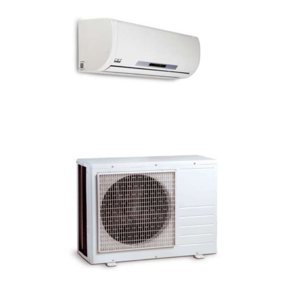
Liquefier The MD 261-351 room air Filter dryer Capillary tube flow regulator conditioning units have a REMKO MD...AT outdoor component as well as an indoor unit MD...IT. Schematic of refrigerant circuit in indoor unit - cooling The outdoor component serves... -
Page 6: Operation
REMKO MD Operation The indoor unit is easy to operate using an infrared remote control. This is supplied as standard. The indoor unit beeps to acknowledge the correct transmission of data. If it is not possible to program the indoor unit using the remote control, it can also be manually operated. - Page 7 Buttons on the remote control Buttons on the remote control "FAN" button Press this button to set the "ON/OFF" Button required fan speed. Press this button to start the 4 settings are available: unit. automatic, high, medium and low fan speed. "MODE"...
- Page 8 REMKO MD Button functions A symbol is shown on the display to indicate that the settings are being transferred. By pressing the ON / OFF button, you can activate or deactivate your ON/OFF Button unit. The programmed settings and adjustment values before the unit was turned off will appear on the display.
- Page 9 In cooling mode, the air in the room is cooled down to the adjusted COOLING Mode nominal temperature. The desired room temperature is set with the ▲/▼buttons in 1 °C increments. If the room temperature is 1 °C above the selected nominal temperature, then the indoor unit starts to cool down the air in the room.
- Page 10 REMKO MD In the heating mode, you can heat the room in spring or fall. The desired HEATING Mode room temperature is set with the ▲/▼buttons in 1 °C increments. If the room temperature is 1 °C below the selected nominal temperature, then the indoor unit starts to warm up the air in the room.
- Page 11 In ventilation mode, the air in the room is only circulated. AIR CIRCULATION Mode The room temperature cannot be changed in this mode. The cooling or heating operation is not activated. MODE AIR CIRCULATION The fan speed can be adjusted with this button. A selection can be made FAN Button between low, medium, high and automatic fan speed.
- Page 12 REMKO MD The activation and switch-off time can be programmed with this button. • TIMER Button TIMER-ON / OFF The timer is activated/deactivated by means of pressing the timer on and the timer off button. The timer symbol ON TIMER or OFF TIMER appears.
-
Page 13: Shutdown
Contact REMKO GmbH & Co. KG or your contract partner for a list of specialist companies near you. Type of task Checks/Maintenance/ Inspections •... - Page 14 REMKO MD Cleaning the housing 5. Any dirt can be cleaned off Cleaning the condensation of the indoor unit using lukewarm water and mild pump (optional equipment) cleaning agents. In order to do 1. Disconnect the supply voltage so, turn the dirty side upward An optional integrated or separate to the equipment.
-
Page 15: Troubleshooting And Customer Service
Troubleshooting and customer service The equipment and components are manufactured using state-of-the-art production methods and tested several times to verify their correct function. If malfunctions should occur, please check the functions as detailed in the list below. Please inform your dealer if the unit is still not working correctly after all the functional checks have been performed! Malfunction Fault... -
Page 16: Installation Instructions For Qualified Personnel
REMKO MD Problem display by blinker code Display Cause Required action Communication error between outdoor component and indoor unit Contact specialist firm Liquefier fan controller faulty Contact specialist firm Sensor evaporator temperature faulty / short-circuited Contact specialist firm Sensor air circulation faulty / short-circuited or... - Page 17 Wall openings Selection of the installation Wind location A wall opening of at least 70 If the unit is being installed in ■ mm diameter and 10 mm slope Indoor unit windy areas, ensure that the from the inside to the outside warm outlet air discharges in the must be made for each indoor The indoor unit is designed for...
- Page 18 REMKO MD Installation inside buildings Ensure there is adequate heat Ensure a continuous and Comply with any regulations ■ ■ ■ dissipation when placing the unobstructed air flow from and conditions affecting outdoor component in cellars, outside, preferably using the statics of the building.
-
Page 19: Installation
Installation Connection variations of Oil return measures NOTE inner unit Installation should only be If the outdoor component is performed by authorised installed at a higher level than Connection variations specialists. the indoor unit, suitable oil return measures must be taken. Usually an oil pump bend is installed Unit installation for every 2.5 metres of height... - Page 20 REMKO MD Connection of refrigerant 5. Verify that the shape of the that they are sufficiently pipes flange is correct(Figure 8). attached and take measures for the oil return, if necessary! The on site connection of the 6. First connect and hand-tighten...
-
Page 21: Tightness Check
Tightness check 12. Ensure that structure-borne Once all the connections have sound is not transferred to parts been established, the pressure of the building. Use vibration gauge station is attached as dampers to reduce the effects follows to the Schrader valve (if of structure-borne sound! fitted): = small valve... -
Page 22: Condensation Connection
REMKO MD Condensation Electrical connection connection When operating the unit at Mains cable must be installed as ■ Due to the dew point shortfall, ambient temperatures below voltage supply to the indoor unit condensation forms on the 0 °C , make sure to route the... -
Page 23: Electrical Connection Diagram
CAUTION If an optionally available Connecting the outdoor ■ condensation pump is used on component Check all plugged and clamped the unit, then - for the shut terminals to verify they are off contact of the pump - an Proceed as follows to connect the seated correctly and making a additional relay to increase the cable:... -
Page 24: Electrical Circuit Diagram
REMKO MD Electrical circuit diagram MD 261-351 IT Vaporiser fan Swing motor Air circulation sensor Sensor Vaporiser Display- screen Mains cable Auto Restart 230V / 1~ /50 Hz to outdoor component Transformer MD 261-351 AT Sensor Vaporiser Display- screen Fuse 1A 250V... -
Page 25: Before Start Up
Before Add refrigerant Commissioning commissioning After the tightness check has CAUTION NOTE been successfully completed, Note that the employed Commissioning should only connect the vacuum pump via refrigerant is always filled in be performed the pressure gauge station to liquid form! and documented by specially the valve connections on the trained personnel. - Page 26 REMKO MD pipe and subtract the boiling 8. Check the indoor unit Final tasks point temperature reading on control system using the functions described in the the pressure gauge from the Re-fit all the dismantled parts. ■ measured temperature. chapter "Operation". Timer,...
-
Page 27: Unit Dimensions
Unit dimensions MD 261 IT / MD 351 IT MD 261 AT / MD 351 AT Dimensional and design changes to advance technical progress are reserved. -
Page 28: Product Illustration
REMKO MD Exploded view MD 261-351 IT We reserve the right to modify the dimensions and constructional design as part of the ongoing technical development process. Spare parts list Designation MD 261 IT MD 351 IT 1109700 1109714 Complete front face... - Page 29 Exploded view MD 261-351 AT We reserve the right to modify the dimensions and constructional design as part of the ongoing technical development process. Spare parts list Designation MD 261 AT MD 351 AT 1109761 1109778 Front panel 1109762 1109779 Fan blade, liquefier 1109763 1109780...
-
Page 30: Technical Data
REMKO MD Technical data Series MD 261 MD 351 Operating mode Inverter-wall room air conditioner combination for cooling and heating Nominal cooling output 2.68 (0.82 to 3.41) 3.56 (1.05 to 4.53) Nominal heating output 2.96 (0.98 to 3.64) 3.86 (1.14 to 4.78) - Page 31 Notes...
- Page 32 This has given us the reputation of being more than just a good and reliable supplier: REMKO, a partner who helps solve problems. Sales REMKO not only has a well- established sales network at home and abroad, it also employs highly trained sales specialists.
Need help?
Do you have a question about the MD Series and is the answer not in the manual?
Questions and answers