Advertisement
Quick Links
Keithley Instruments, Inc.
28775 Aurora Road
Cleveland, Ohio 44139
1-888-KEITHLEY
http://www.keithley.com
Model 8011 High Current Test Socket Kit connection instructions
Before proceeding, please read, understand, and follow all safety precautions provided at the
end of this document (page 14).
The Model 8011 High Current Test Socket Kit is designed for testing high power devices with 2600A Series
SourceMeter instruments and the Model 2651A High Power SourceMeter Instrument at currents up at 50 A pulsed
and voltages up to 40 V.
The Model 8011 includes two test boards, the 8011-DTB and the 8011-CTB, and cables and connectors for
simplifying connections between the SourceMeter instruments and the device. The 8011-DTB Device Test Board is
designed for testing type TO-247 packaged parts and axial components. The 8011-CTB Customizable Test Board
provides a blank space for user customization — the user can use the socket type of his or her choice.
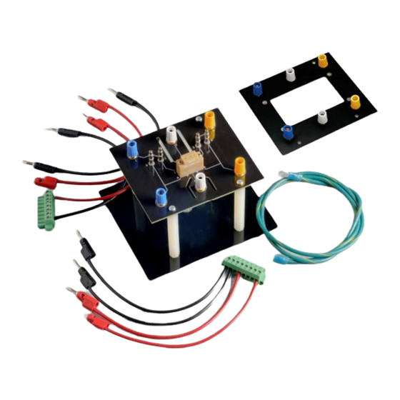
Figure 1. Model 8011 High Current Test Socket Kit*
*Not shown: PA-1032 (these instructions); full set of cables; 8010-317 insulator plugs; and 2600-KIT.
PA-1032 Rev. A / April 2011
Model 8011 High Current Test Socket Kit
Connection instructions
WARNING
1
Advertisement

Related Manuals for Keithley 8011


Summary of Contents for Keithley 8011
- Page 1 (page 14). The Model 8011 High Current Test Socket Kit is designed for testing high power devices with 2600A Series SourceMeter instruments and the Model 2651A High Power SourceMeter Instrument at currents up at 50 A pulsed and voltages up to 40 V.
- Page 2 TO-247 Device Test Board (8010-120; to re-order, use Keithley Model number 8010-DTB) • Customizable Test Board (8010-130; to re-order, use Keithley Model number 8010-CTB) • PA-1032 Model 8011 High Current Test Socket Kit Connection Instructions (this document) • Four nylon hex standoffs with inserts on each end (ST-272-1) •...
- Page 3 Model 8011 Connection Instructions Assembly instructions NOTE If you are customizing the 8010-130 Customizable Test Board, make customizations before assembling the Model 8011. See Figure 2 below. Tools needed • Medium Phillips head screwdriver • 5/16 in. nut driver or socket wrench Assembly instructions 1.
- Page 4 Model 8011 Connection Instructions Figure 2. Model 8011 assembly Four #6-32 x 3/8 Phillips flat-head screws 8010-130 Customizable Test Board 8010-120 TO-247 Device Test Board Four ST-272-1 hex nylon standoffs One #6-32 Keps® washer nut One CA-568-120 green/yellow ground cable with lugs...
-
Page 5: Mounting Instructions
Mounting instructions The 8011-301 mounting plate should be used to secure your test board (8010-120 or 8010-130). It can also be used to secure the assembled Model 8011 to a work surface using the mounting holes shown in Figure 3. - Page 6 Model 8011 Connection Instructions NOTE You can attach your own test board or testing fixture to the 8010-130 Customizable Test Board using the #6-32 screw mounts provided. Figure 4. 8010-130 Customizable Test Board dimensions 3.000 in. (76.2 mm) 1.000 in.
-
Page 7: General Guidelines
Make connections to the SourceMeter instrument before making connections to the Model 8011 boards. • Connect the force leads of the SourceMeter instrument to terminals 4, 5, and 6 of the Model 8011 boards. Connect the sense leads to terminals 1, 2, and 3. - Page 8 Model 8011 Connection Instructions Table 1. Connections for two-terminal device test (local sense) Cable end Cable Cable end Model 2651A rear panel CA-552-1 (supplied with the Model 2651A) Open LO of CA-552-1 Black CA-560-0 8010-120 blue terminal 4 HI of CA-552-1...
- Page 9 Model 8011 Connection Instructions 6. Press the CONFIG key. 7. Press the SRC or MEAS key (the sense mode can be set from either the V-SOURCE or the V-MEAS menu). 8. If you pressed the SRC key, select V-SOURCE > SENSE-MODE.
- Page 10 NOTE If you are using a Model 2600A, do not set the output above 40 V. The Model 8011 is rated to 40 V. You can use the Model 8011 with the 8010-120 board to test a three-terminal device using a Model 2651A High ®...
- Page 11 Model 8011 Connection Instructions Table 3. Connections for three-terminal device test Cable end Cable Cable end Model 2651A rear panel CA-552-1 (supplied with the Model 2651A) Open Model 2651A rear panel CA-557-1 (supplied with the Model 2651A) CS-1629-8 Series 2600A rear panel CA-557-x (recommended;...
- Page 12 NOTE Do not set the Model 2635A or Model 2636A above 40 V. The Model 8011 is rated to 40 V. You can use the Model 8011 with the 8010-120 board to test a three-terminal device using a Model 2651A High ®...
- Page 13 Model 8011 Connection Instructions Table 4. Connections for three-terminal device test Cable end Cable Cable end Model 2651A rear panel CA-552-1 (supplied with the Model 2651A) Open Model 2651A rear panel CA-557-1 (supplied with the Model 2651A) CS-1629-8 Model 2635A or...
-
Page 14: Contact Information
Safety precautions WARNING The 8011 High Current Test Socket Kit is designed to work exclusively with the 2651A High Power System SourceMeter® Instrument and should never be connected to voltage sources that may exceed 40 V DC. The socket should be used within a comprehensive test system (for example, a protective enclosure or safety barrier) that provides adequate safety measures to prevent hazards such as accessible voltage, fire and explosion from causing harm. - Page 15 Keithley Instruments products are designed for use with electrical signals that are rated Measurement Category I and Measurement Category II, as described in the International Electrotechnical Commission (IEC) Standard IEC 60664. Most measurement, control, and data I/O signals are Measurement Category I and must not be directly connected to mains voltage or to voltage sources with high transient over-voltages.
- Page 16 (note that selected parts should be purchased only through Keithley Instruments to maintain accuracy and functionality of the product). If you are unsure about the applicability of a replacement component, call a Keithley Instruments office for information.
Need help?
Do you have a question about the 8011 and is the answer not in the manual?
Questions and answers