Table of Contents
Advertisement
Quick Links
Advertisement
Table of Contents

Related Manuals for Keithley 8010


Summary of Contents for Keithley 8010
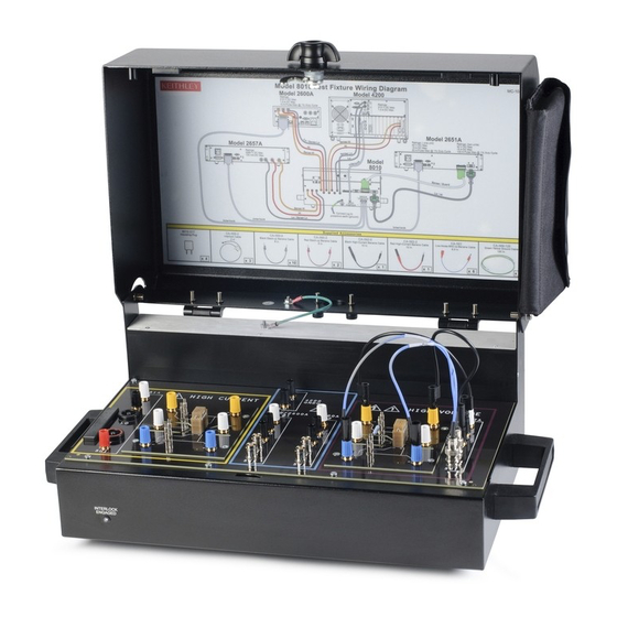
- Page 1 Model 8010 High Power Device Test Fixture Interconnection Reference Guide...
-
Page 2: Safety Precautions
The following safety precautions should be observed before using this product and any Keithley Instruments products are designed for use with electrical signals that are associated instrumentation. Although some instruments and accessories would normally measurement, control, and data I/O connections, with low transient overvoltages, and... - Page 3 Do not exceed the maximum signal levels of the instruments and accessories. Maximum Do not connect switching cards directly to unlimited power circuits. They are intended to be used with impedance-limited sources. NEVER connect switching cards directly to signal levels are defined in the specifications and operating information and shown on AC mains.
-
Page 4: Power And Environmental Characteristics
— including the power transformer, test leads, and input jacks signal voltage Three-lug standard triaxial connector: 210 V — must be purchased from Keithley Instruments. Standard fuses with (signal or applicable national safety approvals may be used if the rating and type are the... -
Page 5: Introduction To The Model 8010 Test Fixture
Model 8010 product documentation in PDF: user-supplied socket types. Interconnection Reference Guide (this document) The Model 8010 allows you to connect one Model 2657 High Power User’s Manual SourceMeter for up to 3000 V testing. You can connect up to two ... -
Page 6: List Of Supplied Accessories
One 10 in. (254 mm) red high-current banana cable (CA-562-2) Six 9.5 in. (241 mm) low noise BNC-banana cable (CA-563) Two document pouches (8010-318) In addition to the Model 8010 Test Fixture, you should have received: Optional and replacement boards that can be purchased are: ... -
Page 7: Attach Pouches To The Test Fixture
4. Position the pouch. Make sure placement of the pouch does not interfere with the closing of the lid or your ability to use the The Model 8010 is intended for use on a bench. Make sure you have handles. -
Page 8: Assumptions For Connection Diagrams
S: Connect to the emitter Using remote sense Note: Remove the 4200-PA Remote Preamplifier when the If you are using remote sense connections, you must enable remote 4200-SCS is connected to the Model 8010 or to the CVU-3K-KIT sense on the instrument. bias tees. -
Page 9: Insulating Plug Use
Insulating plug use To test TO-247 devices, you need to: The Model 8010 comes with insulating plugs that can be used when 1. Remove the insulating plug (if used) from the three-pin socket. testing two-terminal devices. 2. Verify that the four axial device terminal posts are not connected The three-pin socket inherently shorts the force and sense pins to anything. - Page 10 Using both sides of the test fixture In several of the interconnection diagrams, it is noted that you can Do not simultaneously connect terminals in the high current and make equivalent connections on the other side of the test fixture. For high voltage areas of the fixture to the same terminals in the example, if you have an ongoing test using the Series 2600 connected center area (the area bordered in blue).
-
Page 11: Connect The Test Fixture External Wiring (Current-Voltage)
Never connect the guard terminal from any instrument to the LO The international safety standard UL 61010-1: 2004 defines terminal of any instrument in the Model 8010 or to the chassis. voltages as hazardous if they exceed 30 V RMS and 42.4 V peak, Connecting guard to LO can disable the high voltage protection or 60 V DC for equipment rated for dry locations. - Page 12 Hazardous voltages may be present on the output and guard terminals. To prevent electrical shock that could cause injury or The Model 8010 is provided with two protective earth (safety death, NEVER make or break connections to the Model 8010 ground) terminals on the rear panel.
-
Page 13: External Wiring Diagram (Current-Voltage) Measurement Connections
External wiring diagram (current-voltage) measurement connections... -
Page 14: Two-Terminal Axial-Lead Dut With A Model 2651 Connected (Local Sense) (Lid Open View Of Device Test Boards)
Two-terminal axial-lead DUT with a Model 2651 connected (local sense) (lid open view of device test boards) -
Page 15: Two-Terminal Axial-Lead Dut With A Model 2651 Connected (Remote Sense; Current-Voltage)
Two-terminal axial-lead DUT with a Model 2651 connected (remote sense; current-voltage) Note: You may need to add an insulating plug to prevent four-wire remote sense measurement errors. See Insulating plug use for detail. -
Page 16: Two-Terminal Axial-Lead Dut With A Model 2657 Connected (Local Sense)
Two-terminal axial-lead DUT with a Model 2657 connected (local sense) -
Page 17: Two-Terminal Axial-Lead Dut With A Model 2657 Connected (Remote Sense)
Two-terminal axial-lead DUT with a Model 2657 connected (remote sense) Note: You may need to add an insulating plug to prevent four-wire remote sense measurement errors. See Insulating plug use for detail. -
Page 18: Two-Terminal Axial-Lead Dut With A Series 2600 Connected (Local Sense)
Two-terminal axial-lead DUT with a Series 2600 connected (local sense) You can use equivalent connections for the high-current section (this option is not available for a Model 2651 or Model 2657 instrument). -
Page 19: Two-Terminal Axial-Lead Dut With A Series 2600 Connected (Remote Sense)
Two-terminal axial-lead DUT with a Series 2600 connected (remote sense) Notes: You may need to add an insulating plug to prevent four-wire remote sense measurement errors. See Insulating plug use for detail. You can use equivalent connections for the high-current section (this option is not available for a Model 2651 or Model 2657 instrument). -
Page 20: Two-Terminal Axial-Lead Dut With A Model 4200-Smu Connected (Local Sense)
Two-terminal axial-lead DUT with a Model 4200-SMU connected (local sense) -
Page 21: Two-Terminal Axial-Lead Dut With A Model 4200-Smu Connected (Remote Sense)
Two-terminal axial-lead DUT with a Model 4200-SMU connected (remote sense) Notes: You may need to add an insulating plug to prevent four-wire remote sense measurement errors. See Insulating plug use for detail. - Page 22 This page intentionally left blank.
- Page 23 Three-terminal DUT with one or two Model 2651 instruments and Series 2600 instrument connected (remote sense; current-voltage) Note: Multiple Model 2651 instruments will be connected in parallel.
- Page 24 Three-terminal DUT with a Model 2657 and a Series 2600 connected (local sense)
- Page 25 Three-terminal DUT with a Model 2657 and a Series 2600 connected (remote sense)
-
Page 26: Three-Terminal Dut With Two Series 2600 Instruments Connected (Local Sense)
Three-terminal DUT with two Series 2600 instruments connected (local sense) You can use equivalent connections for the high-current section (this option is not available for a Model 2651 or Model 2657 instrument). -
Page 27: Three-Terminal Dut With Two Series 2600 Instruments Connected (Remote Sense)
Three-terminal DUT with two Series 2600 instruments connected (remote sense) You can use equivalent connections for the high-current section (this option is not available for a Model 2651 or Model 2657 instrument). - Page 28 Three-terminal DUT with a 4200 and 2657 connected (local sense)
- Page 29 Three-terminal DUT with a 4200 and 2651 connected (remote sense)
-
Page 30: Three-Terminal Dut With A Model 4200-Smu Connected (Remote Sense)
Three-terminal DUT with a Model 4200-SMU connected (remote sense) Note: The SLO and LO terminals for all Model 42xx SMUs in a Model 4200-SCS chassis are joined in the 4200 GNDU. - Page 31 This page intentionally left blank.
-
Page 34: Cvu-3K-Kit 2-Terminal Dut (Local Sense)
CVU-3K-KIT 2-terminal DUT (local sense) Note that this configuration can be used for testing 2-terminal TO-247 devices, too. When testing 2-terminal TO-247 devices make sure to remove the plug from the socket, if inserted; make sure the four axial device terminal posts are disconnected; place the 2-terminal TO-247 device into the 3-pin socket. -
Page 35: Cvu-200-Kit 2-Terminal Dut (Local Sense)
CVU-200-KIT 2-terminal DUT (local sense)
Need help?
Do you have a question about the 8010 and is the answer not in the manual?
Questions and answers