Table of Contents
Advertisement
Quick Links
Download this manual
See also:
User Manual
Advertisement
Table of Contents

Subscribe to Our Youtube Channel
Related Manuals for Mortara Surveyor S4


Summary of Contents for Mortara Surveyor S4
- Page 1 REF 9516-190-50-ENG Rev G Surveyor S4 Mobile Monitor SERVICE MANUAL Manufactured by Mortara Instrument, Inc., Milwaukee, Wisconsin U.S.A. CAUTION: United States federal law restricts this device to sale by or on the order of a physician.
- Page 2 This document contains confidential information that belongs to Mortara Instrument, Inc. No part of this document may be transmitted, reproduced, used, or disclosed outside of the receiving organization without the express written consent of Mortara Instrument, Inc. Mortara is a registered trademark of Mortara Instrument, Inc. E-Scribe, ELI, and ®...
-
Page 3: Technical Support And Service
European Union Physician Practice: orderspc.us@mortara.com Representative U.S. Distribution: orderspc.us@mortara.com Mortara Instrument Germany Mortara Instrument Europe, s.r.l. Hofgartenstraße 16 (European Headquarters) 72379 Hechingen Via Cimarosa 103/105 Germany 40033 Casalecchio di Reno (BO) Tel.: +49 (0) 7471 98 41 14-0 Italy... - Page 4 TECHNICAL SUPPORT AND SERVICE...
-
Page 5: Table Of Contents
TABLE OF CONTENTS TECHNICAL SUPPORT AND SERVICE ........................1 NOTICES................................1 ’ ............................1 ANUFACTURER ESPONSIBILITY ............................1 ESPONSIBILITY OF THE USTOMER ............................... 1 QUIPMENT DENTIFICATION ..........................1 OPYRIGHT AND RADEMARK OTICES ............................1 THER MPORTANT NFORMATION WARRANTY INFORMATION ..........................3 .............................. -
Page 6: Technical Support And Service
TECHNICAL SUPPORT AND SERVICE ..........................53 IRELESS ETWORK PECIFICATIONS TROUBLESHOOTING ............................55 ..............................55 OWER AND ATTERY ............................. 55 ISPLAY AND OUCHSCREEN ECG T ................................... 55 RACE O 2 ) ..............................56 ULSE OXIMETRY ..............................57 ETWORK RANSMISSION ................................59 RROR ESSAGES ................................. -
Page 7: Notices
The user of this mobile monitor must periodically check the accessories, their functionality and integrity. Equipment Identification Mortara equipment is identified by a serial and reference number on the back of the mobile monitor. Care should be taken so that these numbers are not defaced. Copyright and Trademark Notices This document contains information that is protected by copyright. - Page 8 NOTICES...
-
Page 9: Warranty Information
Product/s returned to Mortara’s principal place or any other place as specifically designated by Mortara or an authorized distributor or representative of Mortara, and (ii) all risk of loss in transit. It is expressly agreed that the liability of Mortara is limited and that Mortara does not function as an insurer. A purchaser of a Product/s, by its acceptance and purchase thereof, acknowledges and agrees that Mortara is not liable for loss, harm, or damage due directly or indirectly to an occurrence or consequence there from relating to the Product/s. - Page 10 WARRANTY INFORMATION...
-
Page 11: User Safety Information
Consult the actual screen in the host language for specific wording. Safety Regulations The Surveyor S4 (henceforth referred to as either Surveyor S4 or S4) is a medical mobile monitor. The S4 and its accessories are labeled, according to applicable standards. - Page 12 Only use the Mortara-provided external battery charger and adapter with the S4. Ensure that the electrical installation also complies with local safety requirements for the environment where it is used.
- Page 13 When the S4 initially powers on, the screen will illuminate if the batteries are installed properly and charged. Remove the S4 from service and contact Mortara if the screen does not activate when new or fully charged batteries are initially installed.
- Page 14 See this manual for disclosure of the pacemaker pulse rejection capability of this instrument. With the Surveyor S4 when used with the 4-wire, 5-wire or 10-wire ECG cable, all pacemaker spikes are rejected per the IEC 60601-2-27 standard (0.1 - 2 ms duration, 2 - 700 mV amplitude). Signals are recognized as pacemaker spikes when they have a slew rate over 4 V/s, as measured according to the IEC 60601-2-27 standard.
- Page 15 USER SAFETY INFORMATION Do not sterilize or immerse pulse oximetry sensors in liquid. Always clean and/or disinfect reusable sensors between patients. Shield the sensor application site from excessive ambient light as necessary when used in the presence of strong light sources such as surgical lights, xenon light sources, ambient photodynamic therapy (e.g.
-
Page 16: Cautions
Mortara for deployment of the system on the hospital/clinic’s IT network. Refer to those requirements as well as Manufacturer Disclosure Statement for Medical Device Security (MDS2) statements provided by Mortara before deploying and using the system. - Page 17 The S4 accommodates single-use or rechargeable internal batteries. If the rechargeable battery appears to become defective, refer to Mortara Technical Support. Do not pull or stretch patient cables as this could result in mechanical and/or electrical failures. Patient cables should be stored off of the floor away from bedrails and wheels to avoid cable damage.
- Page 18 USER SAFETY INFORMATION...
-
Page 19: Equipment Symbols And Markings
Mains power input Consult instructions for use Catalog number for relevant Mortara Serial number part This end up Keep away from sunlight Fragile, handle with care... - Page 20 EQUIPMENT SYMBOLS AND MARKINGS...
-
Page 21: Electromagnetic Compatibility (Emc)
See the appropriate EMC table for recommended separation distances between the radio equipment and the mobile monitor. The use of accessories, transducers, and cables other than those specified by Mortara may result in increased emissions or decreased immunity of the equipment. -
Page 22: Uidance And Anufacturer Declaration Electromagnetic Emissions
ELECTROMAGNETIC COMPATIBILITY (EMC) Guidance and Manufacturer’s Declaration: Electromagnetic Emissions The equipment is intended for use in the electromagnetic environment specified in the table below. The customer or the user of the equipment should ensure that it is used in such an environment. Emissions Test Compliance Electromagnetic Environment: Guidance... -
Page 23: Uidance And Anufacturer Eclaration Lectromagnetic Mmunity
ELECTROMAGNETIC COMPATIBILITY (EMC) Guidance and Manufacturer’s Declaration: Electromagnetic Immunity The equipment is intended for use in the electromagnetic environment specified in the table below. The customer or the user of the equipment should ensure that it is used in such an environment. IEC 60601 Test Compliance Immunity Test... -
Page 24: Recommended Separation Distances Between Portable And Mobile Rf Communications Equipment And The Equipment
ELECTROMAGNETIC COMPATIBILITY (EMC) Recommended Separation Distances Between Portable and Mobile RF Communications Equipment and the Equipment The equipment is intended for use in the electromagnetic environment in which radiated RF disturbances are controlled. The customer or the user of the equipment can help to prevent electromagnetic interference by maintaining a minimum distance between portable and mobile RF communications equipment (transmitters) and the equipment as recommended in the table below, according to the maximum output power of the communications equipment. -
Page 25: Usa And Canada Radio Regulations
ELECTROMAGNETIC COMPATIBILITY (EMC) USA and Canada Radio Regulations USA (FCC) This device is equipped with Transmitter Module with FCC ID:RYYWYSAAVDX7. This device complies with part 15 of the FCC Rules. Operation is subject to the following two conditions: (1) This device may not cause harmful interference, and (2) This device must accept any interference received, including interference that may cause undesired operation. - Page 26 ELECTROMAGNETIC COMPATIBILITY (EMC)
-
Page 27: Maintenance & Cleaning
Display – Verify there are no deep scratches or physical damage to the device display. Inspect the display bezel to ensure it is firmly adhered to the device housing. Contact Mortara technical support if the display or display bezel require replacement. -
Page 28: Cleaning And Disinfecting
MAINTENANCE AND CLEANING Cleaning and Disinfecting The following section provides information on proper cleaning directions for the S4, patient accessories, Li-Ion battery Charger, AC Power Pack and AC Power Cord. Patient accessories should be cleaned before they are applied to a new patient. The mobile monitor should be cleaned as per facility standard of care. The Li-Ion battery Charger, AC Power pack and AC Power Cord should be cleaned in accordance with facility standards pertaining to power components. -
Page 29: Disinfecting Agents
MAINTENANCE AND CLEANING Disinfecting agents The S4 and its Li-ion battery charger are compatible with the following disinfectants: ® Clorox Healthcare Bleach Germicidal Wipes (use according to instructions on product label), or a soft, lint-free cloth dampened with a solution of sodium hypochlorite (10% household bleach and water solution) minimum 1:500 dilution (minimum 100 ppm free chlorine) and maximum 1:10 dilution as recommended by the APIC Guidelines for Selection and Use of Disinfectants. -
Page 30: Cleaning And Disinfecting The Li-Ion Battery Charger
The following table shows the recommended maintenance procedures for the S4, patient accessories, Li-Ion Battery Charger, AC Power Pack and AC Power Cord. The S4 should be serviced once a year by a Mortara authorized service technician; however, it is good practice to periodically ensure the mobile monitor is in proper working order. - Page 31 MAINTENANCE AND CLEANING Functionality Procedure Check for cracks, abrasive edges and other signs of damage. Li-Ion Battery Charger, Check that all connectors and AC cord length is unbroken and smooth along its AC Power Pack, AC length. Power Cord ...
- Page 32 MAINTENANCE AND CLEANING...
-
Page 33: Unit Disassembly
UNIT DISASSEMBLY SECTION 3 This section describes the methods used to disassemble both the generation 1 S4 and the generation 2 S4 mobile monitor, and the tools required to perform the steps defined. The generation 1 S4 can be identified by the flat smooth call button or by PN: S4-P-B. The generation 2 S4 unit can be identified by the indented call button surrounded by a raised ring or by PN:S4-Q-XXX-XXX. -
Page 34: Battery Removal
UNIT DISASSEMBLY S4 Mobile Monitor – Gen 1 (Front S4 Mobile Monitor – Gen 2 S4 Mobile Monitor (Rear View) View) (Front View) Battery Removal The battery compartment is accessible via the removable battery door. 1. Remove the Battery Door by pinching the grips located on each side of the door and remove. - Page 35 UNIT DISASSEMBLY With the battery door assembly (item 1) removed, the battery can be slid away from the battery contacts, in the opposite direction of the battery insertion arrow marked on the lithium-ion battery pack (item 2 shown below). AA Battery removal – Remove the three AA batteries. If the device will continue being operated with AA batteries, the AA Battery Tray (Item 15) can remain inside the battery compartment.
-
Page 36: Sam/Housing Removal
UNIT DISASSEMBLY SAM/Housing Removal Remove the Surveyor ECG Acquisition Module (SAM) from the unit by removing the two Phillips head screws (item 3) from the recessed areas indicated below. Screws should be installed to2 inch/pounds of torque. Slide the SAM from the device housing as shown below. - Page 37 UNIT DISASSEMBLY Remove the six (6) Torx housing screws (item 6) from the areas indicated below. Screws should be installed to 2 inch/pounds of torque. Using a needle nose pliers or tweezers, carefully guide the battery springs and contacts through the housing openings as shown below.
- Page 38 UNIT DISASSEMBLY Carefully remove the Shield Can (item 7), which is held in place by shield can retention clips mounted to the edge of the PCBA and retain it for reassembly. S4 PCBA – Gen 1 S4 PCBA – Gen 2 Remove the wider ribbon cable of LCD assembly by gently moving the latch mechanism in the direction of the arrows with a tweezers.
- Page 39 UNIT DISASSEMBLY Remove the narrow ribbon cable of LCD assembly by gently moving the latch mechanism in the direction of the arrows with a tweezers. S4 PCBA – Gen 1 S4 PCBA – Gen 2...
-
Page 40: Pcba Replacement
UNIT DISASSEMBLY PCBA Replacement 10. Remove the printed circuit board assembly (PCBA – item 8) from the display assembly (item 9). Main PCBA – Gen 1 Main PCBA – Gen 2 Display Assembly – Gen 1 Display Assembly – Gen 2... - Page 41 The items listed in the S4 GEN1 mobile monitor item description listing identify the serviceable level of the device. Subcomponents of assemblies listed are not available as individual service items from Mortara, the assembly level item must be used for servicing purposes.
- Page 42 The items listed in the S4 GEN2 mobile monitor item description listing identify the serviceable level of the device. Subcomponents of assemblies listed are not available as individual service items from Mortara, the assembly level item must be used for servicing purposes.
- Page 43 UNIT DISASSEMBLY S4 Mobile Monitor Item Identification Table Item # Part # Picture 76190-002-70 4800-018 6020-031 SERV 76190-002-50 SERV 76190-002-51 SERV 76190-002-100 SERV 76190-002-50 SERV 76190-002-60 SERV 76190-002-61 SERV 76190-002-110 SERV 76190-002-60 6020-066 8312-033-01 SERV 26025-122-150 SERV 26025-122-151 SERV 26025-122-150...
- Page 44 UNIT DISASSEMBLY S4 Mobile Monitor Item Identification Table Item # Part # Picture 8364-001-51 (Pictured) 8364-001-52 8364-002-51 11083-002-51 (Pictured) 11083-003-51 11083-004-51 (includes label with “11083-002-51” item #) 9042-082-07 9042-082-10 9910-025-50 8364-005-50...
-
Page 45: Conformance Testing
CONFORMANCE TESTING SECTION 4 Conformance testing is to be performed by Authorized Mortara Service Representatives to verify the device is functioning correctly after repair operations have been performed. Testing results should be documented on the test data record at the end of this section of the manual. -
Page 46: Unit Vacuum Leak Test (Ipx4 Rating)
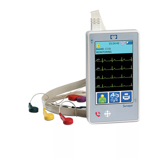
Gen 2 device will require the Call Button to be pressed to initiate power up. The unit should indicate it is receiving power, by the power LED flashing green and the WiFi LED flashing blue. The unit should momentarily display the Mortara logo, then power up to the main screen. - Page 47 CONFORMANCE TESTING Repeat the power up process using the AA battery tray and AA batteries. Main Screen The following diagram depicts the main screen of the S4 with the patient hookup display. Lock Icon Battery Level Indicator Central Station Slot WiFi Signal Strength Name (Unit ID &...
- Page 48 CONFORMANCE TESTING Press the Network button and enter the appropriate method for obtaining an IP address, IP address (if applicable), and security information to connect to the Surveyor Central system. Return to the main menu. Press the WiFi Diagnostics button to test the WiFi connection to the Surveyor Central system. Verify connectivity is established and signal quality information is displayed.
- Page 49 CONFORMANCE TESTING Access the Device Configuration Menu (password 7865) and access the Wi-fi diagnostics menu to find the S4 IP address In the cmd prompt type S4EepromWrite When prompted to Insert S4 IP address/name: enter the IP address found previously on the S4 device When prompted to Insert S4 Serial Number: enter the device serial number When prompted to Insert S4 Part Number: enter the device part number Press any key to exit and return to the directory...
- Page 50 CONFORMANCE TESTING Touch Screen Calibration (Gen 1 device only) On the Surveyor Central System, type Ctrl+Shift+ESC to open Task Manager. Select New Task. Type CMD.exe into the open field and select OK to run the command prompt Type cd and type in the file path the 11010-037 S4 Service and Utility Software is located to change the directory to the S4 test software folder Power on the S4 On the UUT, access the Device Configuration Menu (password 7865) and access the Wi-fi diagnostics menu to find...
-
Page 51: Safety Testing
CONFORMANCE TESTING S4 / Surveyor Central SPO2 Test (Gen 2 Device Only) Note: When starting a session on Surveyor Central, the Unit ID and Bed ID must match between UUT and Central. Verify a normal SPO2 waveform is presented without excessive noise or artifact when clip sensor is placed on the finger. - Page 52 CONFORMANCE TESTING Test Process Place the appropriate Test Fixture Insert into Test Fixture (TF-0579) as follows. For Gen 1 device use TF- 0580 for the 3,4,5-wire SAM, or TF-0581 for the 10-wire SAM. For Gen 2 device use TF-0633 for the 3,5- wire SAM, or the TF-0634 for the 10-wire SAM.
- Page 53 CONFORMANCE TESTING Record a passing test result by checking the box on the test data record. If the test failed, write the reason for failure underneath the safety testing heading on the test data record and do NOT check the box.
-
Page 54: S4 Mobile Monitor Conformance Test Data Record
CONFORMANCE TESTING S4 Mobile Monitor Conformance Test Data Record Unit Serial #: Software Version: Unit Part #: Indicate the step was performed successfully by checking the corresponding check box, and recording test result. IPX4 Vacuum Leak Testing Unit Body Pass/Fail Battery Door Pass/Fail Verify Power Up / LED Operation... - Page 55 CONFORMANCE TESTING Verify 96% +/- 2% Pass/Fail Verify 70% +/- 2% Pass/Fail Verify “CHECK SENSOR” Message with Signal Removed Pass/Fail Verify “NO SENSOR” Message with Cable Removed Pass/Fail Perform Safety Testing Hi-Pot Test Pass/Fail SpO2 Option Hi-Pot Test Pass/Fail/not Installed Device Cleaning Completed Performed by: Date:...
- Page 56 CONFORMANCE TESTING...
-
Page 57: Device Specifications
DEVICE SPECIFICATIONS SECTION 5 General Instrument Type ECG digital mobile monitor 5.5” x 3.1” x 1.3” (139 x 79 x 33 mm) Dimensions Continuous 12-lead signal acquisition and transmission with 10-wire Input Channels LeadForm cable Continuous 7-lead signal acquisition and transmission with 5-wire cables 10-wire: I, II, III, aVR, aVL, aVF, V1, V2, V3, V4, V5 and V6 ECG Leads Transmitted 5-wire: I, II, III, aVR, aVL, aVF, V... -
Page 58: Power Requirements & Battery
DEVICE SPECIFICATIONS Power Requirements & Battery Disposable Battery Type Three (3) AA alkaline batteries Disposable Battery Life 12 Hours Rechargeable Battery Type Rechargeable Lithium-Ion battery pack Rechargeable Battery Run-Time 20 Hours Battery Charging Time 8 Hours ECG Specifications 12-lead ECG with specific Signal Acquisition Module (SAM10) 7-lead ECG with specific Signal Acquisition Module (SAM 5) 10-wire: I, II, III, aVR, aVL, aVF, V1, V2, V3, V4, V5, V6 Simultaneous Leads... -
Page 59: Spo 2 Specifications
DEVICE SPECIFICATIONS specifications Technology Mortara SpO Absorption – Spectrophotometric (dual wavelength) Method (Functional oxygen saturation of arterial hemoglobin) Patient populations Child (greater than 2 through 12 years of age) Adolescent (greater than 12 through 21 years of age) Adult (greater than 21 years of age) - Page 60 DEVICE SPECIFICATIONS Channels 1 to 13 supported. Need to configure used channels on devices prior to installation (default is 1, 6, If dynamic channel selection on WLAN infrastructure is enabled, channels change will cause short data gaps. Reduce the number of channel changes per day. Wireless security protocols WPA2-PSK-AES WPA2-PSK-TKIP (supported but not recommended)
-
Page 61: Troubleshooting
Suggested Resolution Power cycle the S4 and try again. If problems persist, The touchscreen is not Touchscreen failure. stop using the S4 and contact Mortara Technical working properly. Support. Power cycle the S4 and try again. If problems persist, The display is not working Display failure. - Page 62 TROUBLESHOOTING Pulse oximetry (SpO Symptom Possible causes Suggested remedies Signal Quality The physiological signal Check patient status. Consider dark skin pigmentation, low Indicator is sensed by the SpO perfusion, venous pulsation, dysfunctional hemoglobins as sensor is weak yellow;SpO potential factors. values continue to Remove nail polish from sensor site.
-
Page 63: N Etwork T Ransmission
TROUBLESHOOTING Symptom Possible causes Suggested remedies “Artifact” status Excessive patient Advise patient to keep the measurement site still. message movement Select an alternate measurement site less prone to movement. External light source Redirect the external light source away from the produces interference at measurement site. - Page 64 TROUBLESHOOTING Symptom Possible Causes Suggested Resolution Incorrect Host/Central stations Check S4 Host settings and/or Central Station configuration. configuration. "No ECG Monitoring" alarm and no traces on the Central Station. “Trying to connect to Central" error message displayed. Normal symbol on WiFi Mismatch between Unit/Bed ID signal indicator.
-
Page 65: E Rror M Essages
Mismatch of passcodes entered. as the confirmation passcode values match. ECG Frontend calibration failed, restart Power the system on and off. Contact Mortara if the the device. If the Calibration of the ECG frontend failed. problem persists. problem persists contact service. -
Page 66: Wifi Diagnostic
TROUBLESHOOTING WiFi Diagnostics The WiFi Diagnostics screen is for assessing the network interface including confirming network settings, determining signal strength and using a PING tool to test the connection to the Central Station. The IP address of the Central Station defined in the host settings is automatically populated. Another address may be manually entered to test alternative IP address as necessary. - Page 67 TROUBLESHOOTING Once the pass code is correctly entered, the following configuration menu appears, select the WiFi diagnostics option. The WiFi diagnostic screen provides information regarding the IP address, device name, and the MAC address of the S4 monitor. The diagnostic screen also provides information regarding the SSID of the network it is configured to connect to, the MAC address of the access point it is currently connected to, the signal strength (S), the noise floor (N), and the overall quality of the connection to the access point (number of bars).
Need help?
Do you have a question about the Surveyor S4 and is the answer not in the manual?
Questions and answers