Table of Contents
Advertisement
Quick Links
Advertisement
Table of Contents

Related Manuals for Mortara ELI 250


Summary of Contents for Mortara ELI 250
- Page 1 REF: 9516-163-50-ENG Rev: B1 ELI 250 / ELI 210 Service Manual Manufactured by Mortara Instrument, Inc. Milwaukee U.S.A. CAUTION: Use of this service manual is intended for qualified service personnel only. CAUTION: Federal law restricts this device for sale to or on the order of a physician.
- Page 2 Milwaukee, Wisconsin 53224 This document contains confidential information that belongs to Mortara Instrument, Inc. No part of this document may be transmitted, reproduced, used, or disclosed outside of the receiving organization without the express written consent of Mortara Instrument, Inc.
- Page 3 E-mail: sales@mortara.com Europe Economic Mortara Instrument GmbH Community Representative (Germany) Henricistr. 124 45136 Essen Mortara Rangoni Europe, Srl Tel: +49.201.268311 (European Headquarters, Italy) Fax: +49.201.268313 Via Oradour 7 40016 S. Giorgio di Piano, BO Mortara Instrument B.V. Tel: +39.051.6654311 (The Netherlands) Fax: +39.051.6651012...
- Page 4 Equipment Identification Mortara Instrument, Inc. equipment is identified by a serial and reference number on the back of the device. Care should be taken so that these numbers are not defaced. Copyright and Trademark Notices This document contains information that is protected by copyright.
- Page 5 Mortara’s principal place or any other place as specifically designated by Mortara or an authorized distributor or representative of Mortara, and (ii) all risk of loss in transit. It is expressly agreed that the liability of Mortara is limited and that Mortara does not function as an insurer.
- Page 6 UL 2601-1, IEC 601-1 and IEC 601-2-25. • Patient cables intended for use with the ELI 250/210 include series resistance (10 Kohm minimum) in each lead for defibrillation protection. Patient cables should be checked for cracks or breakage prior to use.
- Page 7 Before attempting to use the device for clinical applications the operator must read and understand the contents of the manual and any documents accompanying the device. • Where the integrity of external protective earth conductor arrangement is in doubt, the ELI 250/210 shall be operated from its internal electrical power source. •...
- Page 8 • There is no known safety hazard if other equipment, such as pacemakers or other stimulators, are used simultaneously with the ELI 250/210; however, disturbance to the signal may occur. • If the ECG amplifier input is out of normal operating range, the display will indicate a lead fail for the lead(s) where this...
- Page 9 After operating the ELI 250/210 using battery power, always reconnect the power cord. This ensures that the batteries will be automatically recharged for the next time you use the ELI 250/210. A light will illuminate, next to the on/off switch, indicating that the unit is charging.
- Page 10 viii...
-
Page 11: Table Of Contents
Inspection of Writer Assembly Harness ................2-3 Exterior Inspection ........................2-4 Interior Visual Inspection ......................2-4 Preventive Maintenance Schedule ..................2-4 3 System Settings Access Configuration Menu for the ELI 250................3-1 Summary of Configuration Menus..................3-3 Configuration Page 1......................3-6 Software Version ......................3-6 Cart Number ........................3-6 Site Number .........................3-6... - Page 12 Date Format .........................3-9 Plot Format ........................3-9 Interpretation Option ....................3.9 Reasons........................3-10 Configuration Page 3 ......................3-10 Append to ECG......................3-10 Number of Copies......................3-10 ECG Retrieved......................3-10 Delete Rule ........................3-11 Storage Sensitivity .......................3-11 Auto Save ECG......................3-11 Auto Print ECG ......................3-11 Serial Baud Rate......................3-11 Modem Baud Rate.......................3-11 Use A4 Paper.......................3-11 Caps Lock ........................3-12 Configuration Page 4 ......................3-12...
- Page 13 Testing Continued Serial Port Test ....................6-10 Modem Test .......................6-10 Modem Initialization ................6-10 Receive ECGs ....................6-12 WLAN Test......................6-13 Safety Test ......................6-14 Appendix A ELI 250 Connectivity Chapter Purpose ........................A-1 Transmitting records......................A-1 Direct Connection ........................A-3 Modem Connection .......................A-3 WLAN Transmission......................A-5 LAN Transmission .........................A-6 Patient Request List ......................A-11...
- Page 14 Appendix B ELI 250 Connectivity Options Modem Options ........................B-1 XIRCOM Modem......................B-1 Multitech Modem......................B-3 LAN Option ..........................B-5 Wireless LAN Option ......................B-8...
-
Page 15: General
1 General Service Manual Purpose The purpose of this manual is to supply information to service personnel so they can maintain the ELI 250/210 Interpretive and Non-Interpretive Electrocardiograph at the assembly and subassembly level. Although the manual includes parts lists, mechanical assembly parts, and printed circuit board information, it is intended to function primarily as a guide to preventative and corrective maintenance and electrical repairs considered field repairable. -
Page 16: Sterilizing This Product
Do not sterilize this product or any accessories unless specifically directed by the manufacturer. Sterilization and sterilization environments can seriously damage many components and accessories. Liquid Spills Do not set beverages or other liquids on or near the ELI 250/210, and/or optional equipment. Product Information See Section 1 of Operator's Manual... -
Page 17: Maintenance And Cleaning
Removal of the battery fuse will not cause a loss of ECGs or of the configuration. This information is stored in FLASH memory. Introduction This section provides servicing and maintenance instructions for the ELI 250/210 interpretive electrocardiograph. Subsequent parts of this section are disassembly, inspection techniques, cleaning techniques, and installation. Recommended Cleaning Supplies •... -
Page 18: Cleaning And Inspection Techniques
Clean transformers and inductors with a dry, non-metallic, soft bristle brush. Printed Circuit Board Cleaning The printed circuit board assemblies in the ELI 250/210 system contain static sensitive devices. Use special handling procedures to prevent damage due to ESD. Clean assembled parts with a vacuum cleaner or low pressure compressed air (30 psi). Take care when cleaning printed circuit boards that wires or component leads are not bent back and forth in such a manner as to weaken them and cause them to eventually break. -
Page 19: Metallic And Plastic Parts Cleaning
____________________________________________________________________________Section 2 Metallic and Plastic Parts Cleaning CAUTION Do not wipe over surfaces of nameplates or labels with abrasive cleaners or materials, as this will eventually wear away the nameplate information. Do not use solvents to clean plastic parts. Brush all surfaces and parts with a nonmetallic, soft bristle brush. Wipe metal surfaces with soft, nonabrasive cloth dampened with isopropyl alcohol. -
Page 20: Exterior Inspection
ELI 250/210__________________________________________________________________________ Exterior Inspection Visually inspect the entire instrument for wear, maintenance damage, corrosion, deterioration, and damage resulting from dropping. Interior Visual Inspection Check all connectors for loose, bent or corroded contact points Check wire, harnesses and cables for signs of wear or deterioration. -
Page 21: System Settings
Once you set these default conditions, you will rarely need to use the configuration screens again. When you apply power to the ELI 250, it will operate according to the settings you have selected. To access the configuration menus:... - Page 22 ELI 250/210__________________________________________________________________________ Select Set Time/Date (number 3) from the application menu (SHIFT) + ALT + C. The first From the Set Time/Date screen, simultaneously press configuration screen will appear. Notice the page indicator in the upper right hand corner on...
- Page 23 ____________________________________________________________________________Section 3 Use Page (F4) to toggle through the configuration pages. NOTES: Use ▲ (F1) and ▼ (F2) to move back and forth through each configuration option. Use ► (F3) to toggle through pre-programmed available settings per configuration field. Use Exit (F6) to return to the Real-Time ECG View. Any changes you have made will be saved. Use the BACKSPACE key to erase entry errors.
-
Page 24: Summary Of Configuration Menus
ELI 250/210__________________________________________________________________________ Summary of Configuration Menus Configuration Definition Configuration Screen Parameter Software Version The firmware version of the unit Screen One Cart Number User-defined (4 digits) Screen One Site Number User-defined (4 digits) Screen One Site Name User-defined (up to 30 alphanumeric characters) - Page 25 ____________________________________________________________________________Section 3 Append Unconfirmed Report, Reviewed by, Blank Screen Three #of copies 0 - 9 Screen Three #ECGs retrieved 0 - 9 Screen Three...
- Page 26 ELI 250/210__________________________________________________________________________ Configuration Definition Configuration Screen Parameter Delete Rule Post plot, post transmit, post plot/xmt Screen Three Storage Sensitivity Normal or High Screen Three Auto-save ECG Yes or No Screen Three Auto-print ECG Yes or No Screen Three Baud Rate...
- Page 27 ____________________________________________________________________________Section 3 3 + 3 Rhythm Lead 2 V1-V6, I, II, III, aVR, aVL, aVF Screen Five 3 + 3 Rhythm Lead 3 V1-V6, I, II, III, aVR, aVL, aVF Screen Five Default XMT Media RS232, Modem, WLAN, LAN Screen Six DHCP (LAN only) Yes or No Screen Six...
-
Page 28: Configuration
Cart numbers indicate which electrocardiograph transmitted a particular ECG. Site Number This option identifies the site of your ELI 250. Site numbers designate the hospital, clinic, or institution for ECG records stored in a Mortara Instrument, E-Scribe data management system and must be defined for transmitting and retrieving ECGs from the data management system. -
Page 29: Language
____________________________________________________________________________Section 3 (If necessary, you can use both the letter W and the letter P in the same phone number.) TIP: Instead of entering the configuration menus, use a shortcut to quickly delete or modify a phone number. From the application screen, simultaneously press (SHIFT) + ALT + P. -
Page 30: Configuration
The custom format, which is designed in the Mortara E-Scribe Data Management System, can be downloaded to the ELI 250. The custom ID format is uniquely designed to meet your facility’s needs. Please see Appendix A to download a Custom ID. -
Page 31: Filter
____________________________________________________________________________Section 3 Filter The ECG plot frequency filter (or print filter) can be set to 40Hz, 150Hz, or 300Hz. The plot frequency filter does not filter the acquired digital record. A 40Hz plot filter setting will reduce the noise (40Hz and higher frequencies) on the printed ECG, a 150Hz plot filter setting will reduce the noise (150Hz and higher frequencies) on the printout and a 300Hz plot filter setting will not filter the printed ECG. -
Page 32: Reasons
ELI 250/210__________________________________________________________________________ The ELI 250 automatically analyzes ECGs and prints the optional interpretation on the ECG printout. This option allows you to select or suppress the “interpretive” text on the ECG report. NOTE: A qualified physician should review the computer generated ECG interpretation before the treatment of any patient. -
Page 33: Delete Rule
Use A4 Paper The ELI 250 accommodates use of Z-fold thermal paper in either the letter size (8.5 x 11 inches; 216 x 279 mm) or the “A4” size (8.27 x 11.69 inches; 210 x 297 mm). The provided paper tray spacer is required for use with A4 size paper. -
Page 34: Configuration
ELI 250/210__________________________________________________________________________ Configuration Page 4 Rhythm Formats Configuration page four defines the default values for rhythm printing. It is possible to set a 3-channel, 6-channel or 12-channel default rhythm format. Define rhythm leads one through three to customize a three-channel rhythm printout or define rhythm leads one through six to customize the six-channel rhythm printout. - Page 35 Default XMT Media Configuration page 6 identifies the default transmission media. Those connectivity options which have been optionally purchased and installed (RS232, modem, LAN or WLAN) in your ELI 250 will be available for default selection. DHCP This setting defines whether the Dynamic Host Communication Protocol (DHCP) will be used to obtain an IP address.
- Page 36 WALN. When moving from one area to another, the ELI 250 WLAN card will automatically scan for the channel of the closest access point. Configuration Page 7(optional WLAN connectivity, continued)
- Page 37 Therefore, only devices with the proper WEP will be able to login. The ELI 250 adopts a 128-bit encryption. Access points can have multiple WEP Keys stored. Each one of them is identified by a number (e.g., 0, 1, 2, 3).
-
Page 38: Access Configuration Menu For The Eli 210
ELI 250/210__________________________________________________________________________ Access Configuration Menus for the ELI 210 Three configuration pages define all ELI 210 operational conditions that do not change on a daily or patient-to- patient basis. Once you set these default conditions, you will rarely need to use the configuration screens again. - Page 39 ____________________________________________________________________________Section 3 Select Set Time/Date (number 3) from the application menu. Simultaneously press ▲ (F1) and ▼ (F2). The first configuration screen will appear. There are a total of 3 configuration screens. Notice the page indicator in the upper right hand corner on each screen.
-
Page 40: Summary Of Configuration Menus
ELI 250/210__________________________________________________________________________ Summary of Configuration Menus Configuration Definition Configuration Screen Parameter Software Version The firmware version of the unit Screen One Cart Number User-defined (4 digits) Screen One Site Number User-defined (4 digits) Screen One Language Firmware language availability Screen One Volume Range from 0 –... - Page 41 ____________________________________________________________________________Section 3 Configuration Definition Configuration Screen Parameter Rhythm format 3 channel, 6 channel or 12 channel Screen Three 3 Rhythm Lead 1 V1-V6, I, II, III, aVR, aVL, aVF Screen Three 3 Rhythm Lead 2 V1-V6, I, II, III, aVR, aVL, aVF Screen Three 3 Rhythm Lead 3 V1-V6, I, II, III, aVR, aVL, aVF...
-
Page 42: Configuration
ELI 250/210__________________________________________________________________________ Configuration Page 1 Software Version The displayed number identifies the firmware version of your electrocardiograph. Cart Number Cart numbers indicate which electrocardiograph transmitted a particular ECG. You can use up to four digits for the cart number. Site Number This option identifies the site of your ELI 210. -
Page 43: Ac Filter
____________________________________________________________________________Section 3 This setting determines when the cardiograph will switch off in order to conserve the battery life of the unit. The battery timeout will only occur if the keypad has not been depressed for the time specified. This setting will be ignored while the unit is transmitting, rhythm printing or detects an ECG input signal. -
Page 44: Configuration
ELI 250/210__________________________________________________________________________ Configuration Page 2 Date Format This option defines the format for entering and displaying the patient’s date of birth in either the U.S. format or the European format. For example: July 16 , 2003 is displayed as follows:... -
Page 45: Interpretation Option
____________________________________________________________________________Section 3 10 seconds of 12 leads in a 12 channel format 10 seconds of 12 leads in a 2 page printout (six channels per page) Interpretation Option The ELI 210 automatically analyzes ECGs and prints the optional interpretation on the ECG printout. This option allows you to select or suppress the “interpretive”... -
Page 46: Configuration
ELI 250/210__________________________________________________________________________ Configuration Page 3 Rhythm Formats Configuration page four defines the default values for rhythm printing. It is possible to set a 3-channel, 6-channel or 12-channel default rhythm format. Define rhythm leads one through three to customize a three-channel rhythm printout or define rhythm leads one through six to customize the six-channel rhythm printout. -
Page 47: Assembly/Disassembly Of Unit
FLASH memory. For illustration purposes the ELI 250 will be used to demonstrate the disassembly of the unit. The disassembly of the ELI 210 is identical except for the keyboard components. The parts list located on pages 5-6 and 5-7 of this manual. -
Page 48: Cover Assembly Removal
ELI 250/210 _________________________________________________________________________ Cover Assembly Removal / Installation From the standard operating position: Picture shown is ELI 250... - Page 49 ___________________________________________________________________________ Section 4 Flip unit over so that it is resting on the writer. Locate the mounting screws for the top cover. These are the screws around the perimeter of the unit and marked with arrows in the plastic. Loosen these screws, item number 14 in parts list, using a Philips head screwdriver. Note: When removing screws, loosen the screw and do not remove, the screw can remain in the screw hole by placing tape over the holes with the screw still in the hole.
- Page 50 ELI 250/210 _________________________________________________________________________ Open the writer door approximately 4 to 5 inches.
- Page 51 ___________________________________________________________________________ Section 4 Lift up and rotate the right side of the top cover to left a small distance. Rest the cover on the top of the writer this will allow you to remove the Keyboard/LCD cable, item number 34, from the motherboard. Note: Slide your hand into the unit and disconnect the Keyboard/LCD, item 34, ribbon cable from the motherboard.
- Page 52 ELI 250/210 _________________________________________________________________________ Slide top cover off the unit, rotating as needed to clear the writer door. Set the cover to the side. Re-assemble in reverse order.
-
Page 53: Battery Removal
___________________________________________________________________________ Section 4 Battery Removal Once the top cover is removed, the battery can be accessed for replacement if needed. Make sure that the battery fuse has been removed. Locate the battery, item number 11, near the front of the unit. Slide the cable connections off of the battery. - Page 54 ELI 250/210 _________________________________________________________________________ Remove the LCD cable from the keyboard by 1) sliding the connector to the right then 2) lifting up on the connector.
- Page 55 The silicon key pad, item 9 for the ELI 250 and item 10 for the ELI 210, can now be removed from the keyboard bezel, item 22 for the ELI 250 and item 23 for the ELI 210, along with the LCD.
- Page 56 ELI 250/210 _________________________________________________________________________ When replacing the LCD, remove the old double sided tape and cut a piece of double-sided tape approximately 3 inches. Place this strip of double-sided tape, item number 50, onto mounting surface on Keyboard Bezel as shown.
-
Page 57: Writer Removal / Installation
___________________________________________________________________________ Section 4 Writer Removal / Installation Located on the perimeter of the motherboard are the cables for the writer. There are a total of 5 cables that need to be removed, 2 print head cables, 1 cue sensor cable, 1 print head ground cable and the writer motor cable. Remove the listed cables. - Page 58 ELI 250/210 _________________________________________________________________________ Flip the unit over and remove the 4 screws, item 14, holding the writer to the bottom chassis. CAUTION Due to the weight of the battery, the bottom chassis of the unit may tilt off the writer while the unit is upside down.
-
Page 59: Printhead Removal / Installation
___________________________________________________________________________ Section 4 Printhead Removal / Installation CAUTION The printhead is a static sensitive part. Proper measures should be taken when handling this part. Note: The writer does not need to be removed from the unit for printhead to be replaced however removal of the writer from the chassis will make the job easier. - Page 60 ELI 250/210 _________________________________________________________________________ Carefully guide the printhead assembly out of the writer chassis making sure that no damage occurs to the cables attached to the printhead. Remove the 4 screws, item number52, that attach the printhead to the Printhead plastic support.
-
Page 61: Writer Motor Removal
___________________________________________________________________________ Section 4 Writer Motor Removal / Installation Flip the writer assembly over and locate the writer motor and gear assembly. Remove the three screws that hold this assembly to the writer assembly, item number 53. 4-15... - Page 62 ELI 250/210 _________________________________________________________________________ To remove the writer motor remove the two screws, item number 45, holding it to the gear assembly bracket. The writer motor will slide through the assembly. Use a 0.05 inch or a 1.25 mm size Allen wrench to remove the gear from the writer motor.
-
Page 63: Printed Circuit Board Assembly Removal / Installation
The Motherboard is a static sensitive part. Proper measures should be taken when handling this part. When replacing the motherboard of the ELI 250/210 the configuration will need to be entered on the new board. Prior to replacement, if possible, copy or print out the configuration settings of the old board so that they can be entered when the new board is installed. - Page 64 ELI 250/210 _________________________________________________________________________ Once these cables are removed remove the 2 screws, item 45, at the “front” of the board. Remove the four screws, item number46, at the back of the Motherboard. The Motherboard will now be loose and can be removed from the bottom chassis.
- Page 65 ___________________________________________________________________________ Section 4 CAUTION 1.) When installing a new board, do not replace the battery fuse until all cables have been connected to the board. 2.) The screws that hold the front of the motherboard down are shorter than the screws that hold the back of the motherboard down.
- Page 66 ELI 250/210 _________________________________________________________________________ Locate the 4 screws holding the front-end to the chassis and remove. Note: The screws located near the front end to motherboard interconnect cable will be shorter, item number 45, than those where the patient cable connects to the front end board, item number 46. This is important when reassembling the unit.
-
Page 67: Technical Description
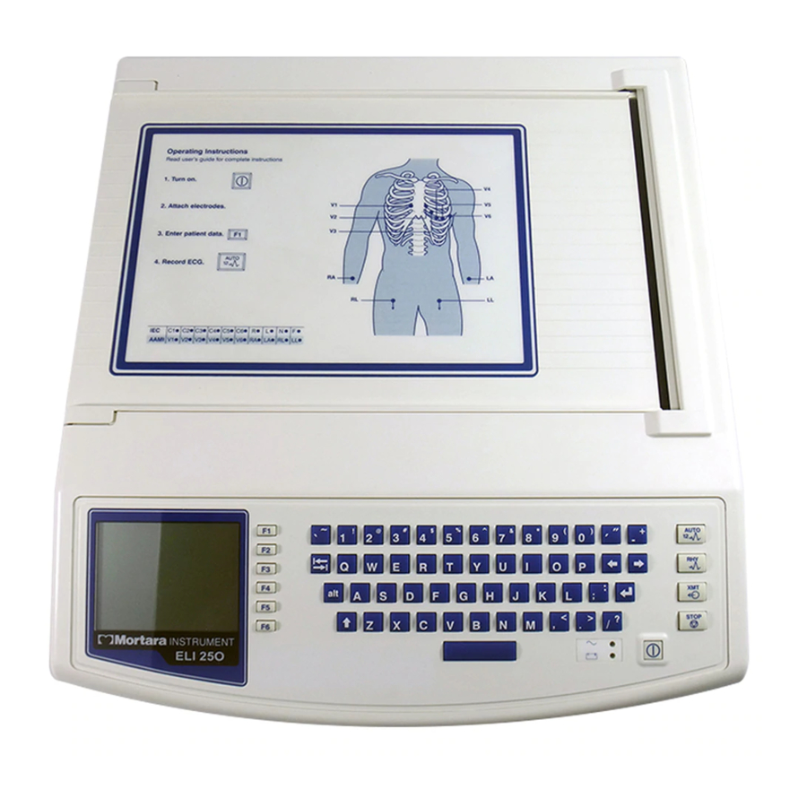
The MORTARA ELI 250/210 is an advanced interpretive electrocardiograph system utilizing the latest electronic technology and software. The ELI 250/210 offers 12-lead patient ECG monitoring, a 320 by 240 LCD display. A full function touchpad keyboard, 8-inch thermal writer for printing waveforms and interpretive data, a real-time electronic clock and calendar, an RS-232 level serial communications port, internal power supply, battery, and battery re-charge circuitry and optional internal MODEM. -
Page 68: Eli 250/210 Block Diagram
ELI 250/210__________________________________________________________________________ ELI 250/210 Block Diagram... -
Page 69: Main System Board
The main system board or motherboard of the ELI 250/210 contains the digital logic circuitry and the power supply of the ELI 250/210. The rear section of the motherboard (located at what is the back of the unit when mounted in the chassis) contains the power supply of the unit. - Page 70 ELI 250/210__________________________________________________________________________ Patient Input Connector: Pin #: Name: Description: Patient Lead Patient Lead Patient Lead Patient Lead Patient Lead SHIELD Isolated Front-End Ground Reserved Reserved Patient Lead Patient Lead Patient Lead Patient Lead Reserved Patient Lead Reserved...
- Page 71 ____________________________________________________________________________Section 5 Specifications * Note – The ECG Storage capability of the ELI210 is 1 ECG...
-
Page 72: Parts List
Part Number Description 26025-039-XX Motherboard PCB Assembly 26025-039-XX Motherboard PCB Assembly 26025-040-51 Keyboard PCB Assembly ELI 250 26025-051-50 Keyboard PCB Assembly ELI 210 26025-043-XX 10k+ Front End Amplifier PCB Assembly 4021-001 Fuse Type T, 250V, 1A, 5 x 20MM SLO... - Page 73 LAN Interface PCB Assembly 6400-010 Cable Ethernet CAT5e RJ45 M SHLD 2FT 25020-061-50 Cable Assy LAN LED ELI 2XX 26025-059-50 MULTITECH Modem Interface PCB Assembly 25018-037-50 Cable Assembly ELI 250 INTRNL 2ND Serial Port 7495-001 Cable Tie/Tie Wrap 3.9 X 0.10...
- Page 74 ELI 250/210__________________________________________________________________________...
-
Page 75: Troubleshooting And Testing
Troubleshooting and Testing Introduction Since repair of the ELI 250/210 is limited to replacement of subassemblies the troubleshooting guide does not extend to the component level NOTE: Remove the battery fuse and AC power during any disassembly necessary for servicing. - Page 76 ELI 250/210__________________________________________________________________________ Unit turns on, no waveform is displayed but function key options are displayed. Press any key on the keyboard, if no response there is a possible communications problem between front end board and motherboard. 1) Replace cable between front end and motherboard.
-
Page 77: Optional Modem Transmit/Receive Problems
____________________________________________________________________________Section 6 Optional Modem Transmit/Receive Problems If the unit does not transmit via the modem the first item to check is the configuration. Make sure that a telephone number is entered and that the number is correct. The next item to check is the modem initialization string (please see the configuration section of this manual or the operator manual). -
Page 78: Testing
ELI 250/210__________________________________________________________________________ Testing Power Supply Test 1.) Remove battery fuse and AC power from the unit. 2.) Open unit to access the connections to the battery. 3.) Remove one of the battery cables from its terminals. 4.) Connect DMM set to a current setting to measure the current that the unit is using. -
Page 79: Date / Time Test
____________________________________________________________________________Section 6 Date / Time Test 1.) Turn the unit on. 2.) Press the F6, More, key. 3.) Press the number 3 key to select the “Date & Time” option. Writer Tests From the main menu press and hold the following key combination Alt + Shift +RHY. The following test strip will be printed. -
Page 80: Adjusting The Writer Cue Sensor
ELI 250/210__________________________________________________________________________ Description of printout At the top of the writer test print out will be the printable characters of the writer. The next section will have a 200-mm line. This line should be measures with a ruler and will indicate if there is a writer motor problem if the line is too short or too long. -
Page 81: Ecg Test
Perform the noise test using a shorting plug of the following design. Please note that Mortara Instrument does not supply this shorting plug 1.) Turn the unit on with the shorting plug connected to the input connector of the unit. -
Page 82: Lead Fail Test
LEADS OFF Transmitting Records You may transmit ECGs from the ELI 250/210 to another Mortara Instrument electrocardiograph or to an E-Scribe Data Management System using a direct connection or an optional factory installed internal modem. Before transmitting ECGs to E-Scribe, the site number must be defined as well as the telephone number in the configuration. - Page 83 ____________________________________________________________________________Section 6 stored ECGs will remain in the directory until it becomes full, at this time, the ELI 250/210 will automatically remove a record, based on its size, in order to make room for the new ECG. Only those records that have been marked for deletion will be removed.
-
Page 84: Serial Port Test
After the transmission of your record(s), the Real-Time ECG View is displayed. Serial Port Test (Direct connect transmission) For a direct connection hookup, connect the ELI 250/210 to another ELI 250/210 with a direct connect serial cable (Mortara P/N: 25000-024). Plug each end of the cable into the serial ports (RS232). - Page 85 ____________________________________________________________________________Section 6 Real Time ECG View Application Menu From the Application Menu, simultaneously press ALT+SHIFT+M to access the modem initialization string. The following screens appear: Approximately 30 second delay Select F2 (+GCI=) to populate the prefix “AT+GCI” of the modem command. 6-11...
-
Page 86: Receive Ecgs
Switzerland India Taiwan Indonesia Thailand Ireland United Kingdom Israel United States Italy Venezuela Receive ECGs To receive ECGs from another Mortara Instrument electrocardiograph (using either a telephone or a direct connection), select Receive ECGs (4) from the Application Menu. 6-12... -
Page 87: Wlan Test
Received ECGs will not be viewed or stored. To terminate the receiving mode, press the STOP key. Note: The ELI 250/210 will receive records from Mortara model cardiographs. The Mortara model cardiographs (ELI 100, ELI 200, Landscape, and Portrait) will not receive the ELI 250/210 records. -
Page 88: Safety Test
ELI 250/210__________________________________________________________________________ Channel Number: WEP info (if used) Once this setup is completed ECGs can be transmitted by pressing the “XMT” key from the main menu and selecting the record you wish to send. Transmission information can be viewed in the test software window. -
Page 89: Appendix A Eli 250 Connectivity
Custom ID Transmitting Records You may transmit ECGs from the ELI 250 to another Mortara Instrument electrocardiograph, to an E-Scribe Data Management System, or to ELI LINK using a direct connection, an optional factory installed internal modem, or network connection. - Page 90 ECG at a later time. All stored ECGs will remain in the directory until it becomes full, at this time, the ELI 250 will automatically remove a record, based on its size, in order to make room for the new ECG.
-
Page 91: Direct Connection
For a modem transmission, set the Default XMT media to Modem from Configuration page 6 (see section 3 of this manual). Connect the ELI 250 to a standard telephone jack with the provided phone line cable. Plug the cable into the telephone jack located on the back of the cardiograph and the other end into a telephone wall jack. - Page 92 ELI 250/210__________________________________________________________________________ From the Application Menu, simultaneously press ALT+SHIFT+M to access the modem initialization string. The following screens appear: Approximately 30 second delay From the Configure Modem screen, select F2 (+GCI=) to populate the prefix “AT+GCI” of the modem command.
-
Page 93: Wlan Transmission
__________________________________________________________________________Appendix A Canada Netherlands Czech Republic New Zealand China Norway Denmark Poland Finland Portugal France Russia Germany South Africa Greece Singapore Guam Slovak Republic Hungary Spain Hong Kong Sweden Iceland Switzerland India Taiwan Indonesia Thailand Ireland United Kingdom Israel United States Italy Venezuela Blind Dialing for Xircom Modems... -
Page 94: Lan Transmission
Note: the range for the WEP Key on the ELI 250 is 0-3. If the range on your access point is 1-4, then 0 at the ELI 250 maps to 1 on the access point; 1 at the ELI 250 maps to 2 on the access point, etc. - Page 95 ELI 250, the left LED remains illuminated when the network link is detected. The ELI 250 LAN will support signaling rates of 10 and 100 MBPS. The right LED flashes when a transmit or receive packet occurs or any traffic on the network is detected.
- Page 96 Received ECGs will not be viewed or stored. To terminate the receiving mode, press the STOP key. Note: The ELI 250 will receive records from Mortara model cardiographs except for Mortara’s Portrait. The Mortara model cardiographs (ELI 100, ELI 200, Landscape, and Portrait) will not receive the ELI 250 records.
- Page 97 ECGs are retrieved by ID number. Enter the desired ID and select F1. E-Scribe transmits the most recent ECG with the specified ID number (or the configured number of ECGs retrieved– refer to Section 3). The ELI 250 prints the retrieved ECG(s) and returns to the Real-Time ECG View.
- Page 98 ELI 250/210__________________________________________________________________________ Under the heading “Site Selection”, the Request Code is displayed. Use F1 (F1) and (F2) to scroll through the available Request Codes. Request Codes are only available if a Custom ID has been downloaded. Once you find the desired Request Code, Select F3 (Selec) to download the Requests and the following screen appears: NOTE: A Custom ID must be downloaded before downloading the Requests.
-
Page 99: Patient Request List
__________________________________________________________________________Appendix A When the Request List has been downloaded, you may select the patients who need ECGs. Select ID (F1) from the Real-Time ECG View. Real Time ECG View Patient ID Patient Request List Select Req (F4) from the Patient ID screen and the Patient Request List is displayed. The Patient Request List is comparable to the Patient Directory in looks and in practice. - Page 100 ELI 250/210__________________________________________________________________________ Select F1 to sort the requests by patient name (ID, time & date are displayed on the top row) Select F2 to sort the requests by patient ID (name is displayed on the top row) Select F3 to sort the requests by acquisition date (name is displayed on the top row) To make a printout of the Patient Requests List, select Print Requests (F4).
-
Page 101: Custom Id Download
Custom ID formats are uniquely defined by your facility’s needs. This customized ECG header information is designed in the Mortara E-Scribe data management system and downloaded to the ELI 250 as the Group Name either by serial connection (direct) or modem transmission. - Page 102 ELI 250/210__________________________________________________________________________ “Waiting for Response”, “Connected”, and “Custom ID downloaded” will be displayed before returning to the Real- Time ECG View, which indicates the Custom ID download is complete. The new Custom ID becomes the customized header format for all future ECGs until you select a different ID format in the configuration settings.
-
Page 103: Appendix Beli 250 Connectivity Options
Modem Options There are two possible modems that the ELI 250 can contain. The first is the XIRCOM modem and the second is the Multitech modem. Each modem is an internal modem. The Xircom modem is a PCMCIA modem and must be placed into the bottom slot of the motherboards PCMCIA connector. - Page 104 ELI 250/210__________________________________________________________________________ Xircom Modem Removal 1. Remove the top cover and the writer assembly. 2. Locate the mounting screws, item 48, and bracket, item # 42, for the modem and remove them. 3. Remove the cable, part of item # 55, connected directly to the modem. If needed cut the cable ties, item # 63, that hold this cable to the chassis of the unit.
-
Page 105: Multitech Modem
Multitech Modem The Multitech modem is a separate board, item #61, installed near the rear of the ELI 250 unit. There is one ribbon cable, item #62, that connects the motherboard to the Modem Interface board. This cable connects power and data to the modem. - Page 106 ELI 250/210__________________________________________________________________________ 3. Locate the 4 mounting screws , item # 45, for the modem and remove them. 4. The Modem Interface Board should lift out of the unit. 5. Install the new or replacement board in the reverse order.
-
Page 107: Lan Option
__________________________________________________________________________Appendix B LAN Option The LAN, Local Area Network, option consists of two circuit boards and two interconnect cables. The first card, the LAN card (item #57) occupies the top slot of the PCMCIA slots on the motherboard. The second board is the LAN interface board, item #58, and is mounted inside the chassis near the rear of the unit. - Page 108 ELI 250/210__________________________________________________________________________ Removal of the LAN Interface Board, item #58. 1. Open the unit to access the motherboard 2. Locate the LAN Interface board. Item number 58, near the back of the unit. 3. Remove the cables, item #s 59 and 60, from the LAN Interface board.
- Page 109 __________________________________________________________________________Appendix B LAN Card Interconnect cables. The picture below shows the positions of the LAN Interconnect cables, items 58 and 59. Please note that the cables are tie wrapped, item # 63, to the chassis of the unit to prevent the cables from coming in contact with the motherboard.
-
Page 110: Wireless Lan Option
ELI 250/210__________________________________________________________________________ Wireless LAN Option The Wireless LAN option is a PCMCIA card that connects to the bottom slot of the PCMCIA connector of the motherboard. - Page 111 __________________________________________________________________________Appendix B Wireless LAN card (WLAN) Removal 1. Open the unit to access the motherboard. 2. Locate the WLAN card, item number 41, connected to the PCMCIA slot on the motherboard. 3. Remove the E-clip, Item #42 and 48, that retains the WLAN card. 4.
Need help?
Do you have a question about the ELI 250 and is the answer not in the manual?
Questions and answers
the machine goes through all the process but when it is time to print a message say "unsaved " so nothing prints on the paper. the EKG Machine is an ELI250
The "unsaved" message on the Mortara ELI 250 EKG machine when attempting to print likely means that the ECG has not been stored in memory and therefore cannot be printed.
This answer is automatically generated
How ECG automatic report/interpretation can be eliminated?
ECG SALE COMO SI LE FALTARA TINTA, POR ES ESO
Changed the paper now nothing gets printed at all