
Related Manuals for Mortara H12+


Summary of Contents for Mortara H12+
- Page 1 REF 9516-160-50-ENG Rev B1 H12+ SERVICE MANUAL Manufactured by Mortara Instrument, Inc., Milwaukee, Wisconsin U.S.A. CAUTION: Federal law restricts this device to sale by or on the order of a physician.
- Page 3 7865 N. 86th Street Milwaukee, Wisconsin 53224 This document contains confidential information that belongs to Mortara Instrument, Inc. No part of this document may be transmitted, reproduced, used, or disclosed outside of the receiving organization without the express written consent of Mortara Instrument, Inc.
- Page 5 E-mail: sales@mortara.com Hospital Customers: orders.us@mortara.com European Union Physician Practice: orderspc.us@mortara.com Representative U.S. Distribution: orderspc.us@mortara.com Mortara Instrument Germany Mortara Instrument Europe, s.r.l. Bonifaciusring 15 (European Headquarters) 45309 Essen Via Cimarosa 103/105 Germany 40033 Casalecchio di Reno (BO) Tel: +49.201.18 55 69 70...
- Page 6 Failure to do so may cause undue failure and possible health hazards. Equipment Identification Mortara Instrument equipment is identified by serial numbers on the back or bottom of the device. Care should be taken so that these numbers are not defaced.
- Page 7 Mortara should be found liable to anyone under any theory (except the expressed warranty set forth herein) for loss, harm or damage, the liability of Mortara shall be limited to the lesser of the actual loss, harm or damage, or the original purchase price of the Product when sold.
- Page 8 User Safety Information Note: Provides information to further assist in the use of the device. Equipment Symbols Symbol Delineation CAUTION: Means there is the possibility of damage to the equipment. Anti-Static equipment should always be worn when working with static sensitive devices and in a static sensitive area.
-
Page 9: Table Of Contents
Table of Contents General Service Manual Purpose ........................1-1 User Safety Information ........................1-1 Periodic Safety Inspections ......................1-1 Do Not Mount Product above Patient ..................1-1 Proper patient Cable ........................1-1 Recommended Accessories ......................1-1 Sterilizing this Product........................1-1 Liquid Spills .......................... - Page 10 H12+ Disassembly Parts List ..........................4-1 Opening the Unit ........................4-2 Keypad Removal ........................4-4 LCD Removal & Replacement ....................4-5 Digital Board Removal & Replacement ................. 4-7 Front End Board Removal & Replacement ................4-8 Printed Circuit Boards Introduction ..........................5-1 Flow Chart ..........................
-
Page 11: General
Manufacturer's Warranties and/or responsibilities. If you are not able to correct the H12+ Holter Recorder’s questionable operating state using the Troubleshooting guide in the Operator's Manual, do not attempt to service it yourself. Contact Mortara Service at 1-888- MORTARA (667-8272). -
Page 12: Equipment Symbols
H12+ Equipment Symbols Symbol Delineation Electrostatic sensitive devices... -
Page 13: Maintenance And Cleaning
Section 2 Maintenance and Cleaning Introduction This section provides servicing and maintenance instructions for the H12+ Holter Recorder. Subsequent parts of this section are disassembly, inspection techniques, and cleaning techniques. Recommended Interior Cleaning Supplies Anti-static mat & wrist band, properly grounded ... -
Page 14: Metallic And Plastic Parts Cleaning
H12+ Metallic and Plastic Parts Cleaning CAUTION Do not wipe over surfaces of nameplates or labels with abrasive cleaners or materials, as this will eventually wear away the nameplate information. Do not use solvents to clean plastic parts. Exterior Cleaning Use a damp cloth to clean external covers and the patient cable. -
Page 15: Batteries Removal / Installation
Remove the battery door. Remove the Battery. Check battery connection terminals for debris and/or corrosion. CAUTION Be sure that the polarity of the batteries is correct. Follow diagram in cover. Use only Mortara approved Alkaline replacement batteries (Mortara part #4800-001). Re-install the batteries. - Page 16 H12+...
-
Page 17: Technical Description
Section 3 Technical Description H12+ Overview Instrument Type: 12-lead ECG Holter Recorder Simultaneous acquisition of all leads. Input channels: I,II,III,aVR, aVL, aVF, V1, V2, V3, V4, V5, & V6 Standard leads acquired: Meets or exceeds the requirements of ANSI / AAMI EC38 Input impedance Input Dynamic Range Electrode Offset Tolerance... -
Page 18: Opening And Closing The Battery Door
H12+ H12+ Digital Recorder The compact flash card slot and the battery compartment are accessible via the battery door of the H12+ Recorder. Opening and Closing the Battery Door To open the battery door, hold the latch (1) down and then depress and slide the battery door (2) until it stops. Lift and remove the battery door. -
Page 19: Inserting And Removing Flash Cards
Section 3 Inserting and Removing Flash Cards To insert or remove a flash card, open the battery door of the H12+. Locate the card slot and the Eject button located to the right of the card slot on the inside of the H12+. Note: The Eject button has two positions: Up (card properly inserted) and Down (card ejected). -
Page 20: Attaching The Patient Cable
H12+ Attaching the Patient Cable The LeadForm Patient Cable consists of a connector block, main cable and ten leadwires connected to the main cable. Each leadwire terminates in a snap connector. The leadwires are positioned on the main cable to follow the contour of the torso. -
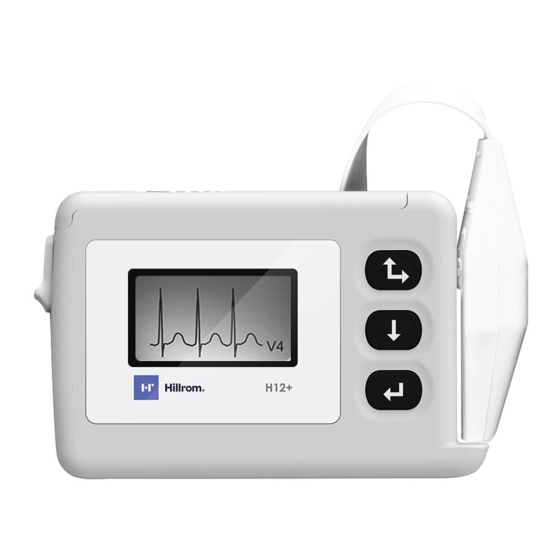
Page 21: Using The Keypad
Section 3 Using the Keypad The keypad is located on the front, right-side of the H12+ Recorder. Three keys are available for navigating through the LCD screens and for entering the patient ID and event markers during the recording. These include the Up/Right, Down and Enter keys. - Page 22 H12+ The LEAD CHECK, DISPLAY ECG, ENTER ID and CONFIGURE tasks are performed prior to starting a new patient recording. With the exception of CONFIGURE, the other three tasks typically are done for each new recording. Note: Patient ID entry (ENTER ID) is optional. If desired, the patient ID may be entered after the patient record is downloaded to the H-Scribe system.
-
Page 23: Lead Check
Section 3 The Main menu options are displayed in the middle of the screen with Up ‘▲’ and Down ‘▼’ indicators above and below the option to indicate how to scroll to the next option. The current time and date are displayed at the bottom of the screen. -
Page 24: Display Ecg Leads
H12+ Displaying ECG Leads DISPLAY ECG is used to visually inspect leads I, II, III, V1, V2, V3, V4, V5 and V6 before starting a recording. Check the signal quality and lead amplitude for each lead. From the Main menu, scroll to DISPLAY ECG using the Down or Up key. Press the Enter key to select this option. -
Page 25: Configuring Date/Time And Language
Section 3 To enter a space, move the cursor to the last line and position the cursor over the blank space following the last letter. Press the Enter key to input a space in the patient ID. To delete a letter or digit in the patient ID, position the cursor over Del on the bottom line. Press the Enter key to delete the last letter or digit entered in the patient ID. - Page 26 H12+ 3-10...
-
Page 27: Setting Date And Time
Section 3 Setting Date and Time DATE/TIME is used to set the current date and time and to set an alternative format for the displayed date. From the Configuration menu, scroll to DATE/TIME using the Down or Up key. Press the Enter key to select this option. -
Page 28: Viewing Software Version Number
H12+ Viewing Software Version Number VERSION displays the current software version installed in the H12+. From the Configuration menu, scroll to VERSION using the Down or Up key. Press the Enter key to return to the Configure menu. The top number indicates the software version on the H12+, in this case version 03.10, and the bottom number indicates the bootcode version number, in this case 003. -
Page 29: Entering (Optional) Diary Events
Section 3 During normal operation, the current time (HH:MM:SS) is displayed in the middle of the screen continuously for the entire 24-hour recording session. The Recording message is displayed below the current time. 10:26:20 Recording If during recording the battery door is removed, the H12+ stops recording. A new formatted flash card must be installed to continue recording. - Page 30 H12+ 3-14...
-
Page 31: H12+ Disassembly
Manufacturer's Warranties and/or responsibilities. If you are not able to correct the H12+Holter Recorder Module’s questionable operating state using the Troubleshooting guide in the Operator's Manual, do not attempt to service it yourself. Contact Mortara Service at 1- 888-MORTARA (1-888-667-8272) or via email at TechSupport@mortara.com. -
Page 32: Opening The Unit
H12+. If the serial number label is damaged when the back label of the H12+ is removed please contact Mortara Instrument for a replacement serial number label. The serial number and the REF number must be supplied. - Page 33 Section 4 Battery door latch, item #4 and spring, item # 16...
-
Page 34: Keypad Removal
H12+ Keypad Removal 1. Open the unit (see step above) 2. Flip the top cover over and remove the rubber keypad, item # 9. 3. Install new keypad. 4. Reassemble unit in reverse order using 2.5 in/lbs torque driver with a 1# phillips bit. -
Page 35: Lcd Removal & Replacement
Section 4 LCD Removal & Replacement 1. Open unit as described above. 2. Locate LCD cable on Digital board. 3. Remove the foam tape (item# 12) covering the LCD cable. 4. Locate the LCD Cable connector on the digital board. 5. - Page 36 H12+ 6. Lift the LCD, item # 11, and plastic shell off the digital board. 7. Remove and replace the LCD. 8. Install LCD and reassemble unit in reverse order using 2.5 in/lbs torque driver (Brown) with a 1# phillips bit...
-
Page 37: Digital Board Removal & Replacement
Section 4 Digital Board Removal & Replacement 1. Open unit as described above. 2. With the unit open, lift up on the Digital board (item # 6, 23 or 24) to remove it from its mating connectors. 3. Install digital board in reverse order. 4. -
Page 38: Front End Board Removal & Replacement
H12+ Front End Board Removal & Replacement 1. Open unit as described above. 2. Remove Digital board, item # 6, as described above. Please note that the LCD does not require removal. 3. Locate the two mounting screws, item # 17, holding the Analog board, item # 18, to the chassis of the unit and remove. - Page 39 Section 4 5. Replace/install analog board and reassemble unit in reverse order using 2.5 in/lbs torque driver with a 1# phillips bit.
- Page 40 H12+ 4-10...
-
Page 41: Printed Circuit Boards
Section 5 Printed Circuit Boards Introduction This section provides illustrations of the H12+ Holter Recorder Printed Circuit boards. The parts list has not been provided. Boards are to be ordered for replacement as a whole. Refer to Safety Test in the section for Testing and Troubleshooting. - Page 42 H12+ H12+ Front End PC Board Assembly REF: 26025-031-50...
- Page 43 Section 5...
- Page 44 H12+ Block Diagram of H12+ Front End Board...
- Page 45 Section 5 H12+ Digital PC Board Assembly REF: 26025-030-50...
- Page 46 H12+...
- Page 47 Section 5 Block Diagram of H12+ Digital Board...
- Page 48 H12+...
-
Page 49: Testing And Troubleshooting
Manufacturer's Warranties and/or responsibilities. If you are not able to correct the H12+ Digital Recorder questionable operating state using the Troubleshooting guide in this manual, do not attempt to service it yourself. Contact Mortara Technical Support if servicing assistance is needed. - Page 50 H12+ High Lead Quality Test Fixture TF-0346 H12+ Low Lead Quality Test Fixture Digital Multi-Meter Variable Power Supply Mortara H-Scribe II TF0553 H12+ Serial number/Date time Compact Flash Card 4.0 Initial Set-up 4.1 Set adjustable power supply to 1.35V ± 0.05V.
- Page 51 Section 6 Compact Flash Card Test 6.2.1 Adjust the variable power supply to 1.55V ± 0.05V. 6.2.2 Cycle the power on the power supply. 6.2.3 Verify lead check is displayed on the LCD. 6.2.4 Record result on the TDR. Real-Time Clock Memory Test 6.3.1 Navigate to the date format setting in the device menu options.
- Page 52 Verify that all of the bars on the LCD are at or below the horizontalline. Record result on the TDR. Current Consumption Test 6.6.1 Leave TF-0346 connected to the UUT. 6.6.2 Connect DMM to TF-0347 and setup meter to read current. 6.6.3 Set the current switch on TF-0347 to measure.
- Page 53 Section 6 APPENDIX A If the Front End Control Test fails, a failure code will be displayed on the LCD. This failure code will be in decimal. Convert the code to binary and refer to Table 1 to determine which test(s) failed.
-
Page 54: Safety Test
SAFETY TEST INTRODUCTION: This procedure describes the safety test for the fully assembled H12+ Recorder. This test can only be done to units which have the back label attached. REQUIRED EQUIPMENT High Voltage AC Supply (1.5kV) H12/X12 Safety Test Fixture (TF-0014) CAUTION: DANGEROUS VOLTAGES PRESENT, USE CAUTION AT ALL TIMES PROCEDURE:... - Page 55 Section 6 H12+ Test Data Record Unit Serial #: 6.1 Low Battery Test PASS / FAIL (CIRCLE ONE) 6.2 Compact Flash Card Test PASS / FAIL (CIRCLE ONE) 6.3 Real-Time Clock Memory Test PASS / FAIL (CIRCLE ONE) 6.4 SDRAM / Front End Control Test PASS / FAIL (CIRCLE ONE) Lead Quality Test PASS / FAIL (CIRCLE ONE)
-
Page 56: Required Safety Test For Printed Circuit Boards
Required Safety Test for Printed Circuit Boards NOTE: Any component replacement to PCB assembly, requires a High Voltage Test and it is recommended that the unit be sent back to Mortara Service Department for repair and testing. Troubleshooting Trouble Symptoms... - Page 57 Section 6...
-
Page 59: Log File Information
Section 7 Log File Information Introduction The H12+ Holter recorder generates several files when recording a monitoring session. One of these files, the log.txt file, can be useful in determining problems or events that occurred during a monitoring session. This file is accessible after the FLASH card data has been downloaded to the H-Scribe computer system. -
Page 60: Mode Section
H12+ Section 2 Mode section Section 2 of the log.txt file contains information regarding what happens prior to the actual data recording. This will include entries for: Mode description Value entered in log.txt file Main_Menu Impedance Waveform Recording Configuration DATETIME Menu Language Version Set Date &... -
Page 61: Fault Section
Section 7 Mode 5 Configuration An entry of Mode 5 (Configuration) means that the configuration menus have been accessed. Mode 6 Date & Time menu An entry of Mode 6 (Date & Time) means that the Date & Time menus have been accessed. Mode 7 Language An entry of Mode 7 (Language) means that the Language menus have been accessed. - Page 62 H12+...
Need help?
Do you have a question about the H12+ and is the answer not in the manual?
Questions and answers