Table of Contents
Advertisement
Quick Links
Engineered Solutions
Making Geothermal Easier
Installation, Operating, and Maintenance Manual
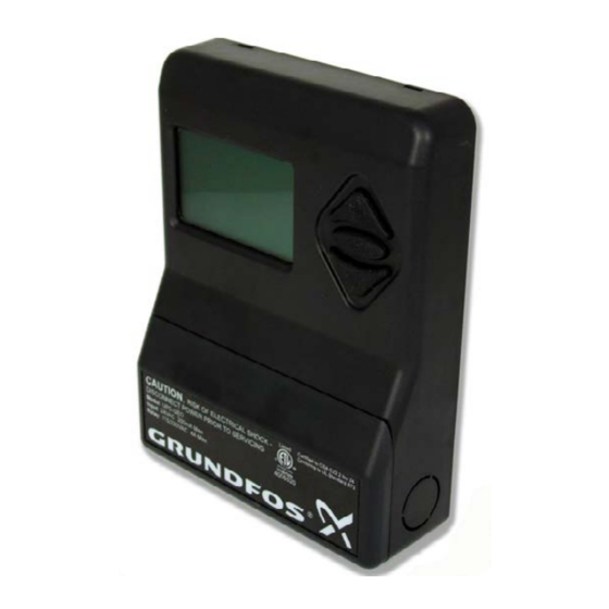
Geo-Flo Universal Pump Controller (UPC-GEO) by Grundfos
Geo-Flo Products Corporation
905 Williams Park Drive
Bedford, Indiana 47421, U.S.A.
3704-07-05-16
www.geo-flo.com
Document # 3704
Rev. 05JUL2016
Main Number:
Toll Free:
Fax:
812-275-8513
800-784-8069
888-477-8829
Advertisement
Table of Contents


Need help?
Do you have a question about the Geo-Flo Universal Pump Controller and is the answer not in the manual?
Questions and answers