Advertisement
Advertisement
Table of Contents

Subscribe to Our Youtube Channel
Related Manuals for Victron energy Skylla-i 24/80 (1+1)


Summary of Contents for Victron energy Skylla-i 24/80 (1+1)
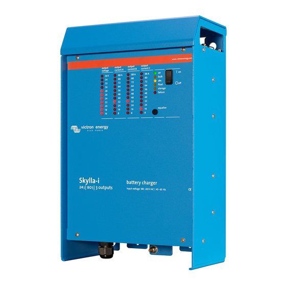
- Page 1 Manual Skylla-i 24/80 (1+1) 24/80 (3) 24/100 (1+1) 24/100 (3)
- Page 3 VICTRON ENERGY PRODUCTS DESCRIBED HERE IN. Victron Energy B.V. reserves the right to revise and improve its products as it sees fit. This publication describes the state of this product at the time of its publication and may not reflect...
-
Page 5: Safety Instructions
1. SAFETY INSTRUCTIONS 1.1. General Please read the documentation supplied with this product first, so that you are familiar with the safety signs and directions before using the product. This product is designed and tested in accordance with international standards. The equipment should be used for the designated application only. -
Page 6: Installation And Wiring
2. INSTALLATION AND WIRING 2.1. Installation Find a dry and well-ventilated area to mount the Skylla charger and battery. Keep the cable length between the charger and the battery less than 6 meters. The charger may be wall or floor mounted. Vertical mounting improves the air circulation within the charger cabinet and will prolong the lifetime of the battery charger. - Page 7 Connecting earth Connect the grounding point (5) to a real earth-point. Connections to earth have to be according to applicable safety standards. On a ship: connect (5) to the earth plate or to the hull of the ship. • On land: connect (5) to the earth of the mains. The connection to the earth of the mains has to be according to •...
- Page 8 +: Main battery plus -: Main battery minus Starter battery plus Figure 3 Location of battery connections: two output models Note: The starter battery can draw current from the battery connected to the main battery terminals in case the starter battery voltage is lower than the main battery voltage.
-
Page 9: Remote On/Off
2.3. Other options The wiring of these signals must be done with the mains disconnected from the charger. ONNECTION BLOCK FOR EXTERNAL SENSORS SWITCH AND RELAY Voltage Temperature Remote Alarm relay sensor sensor on/off Figure 5 Connector block 2.3.1. External voltage sensor (see fig 3) External voltage sensing may be used when accurate battery voltage sensing is important, such as high charging currents in combination with long cables. - Page 10 2.3.6. Synchronised parallel operation Several chargers can be synchronised with the CAN interface. This is achieved by simply interconnecting the chargers with RJ45 UTP cables (bus terminators needed, see section 2.3.5). The paralleled chargers must have identical DIP switch and rotary switch settings . A mix of Skylla-i 100A and 80A chargers can be paralleled.
- Page 11 3.1. Rotary switch The rotary switch provides the user with a selection of preset battery types to be charged. See table below. Warning: the charge voltages as given below are indicative only. Always refer to the battery supplier for the right charge voltages.
- Page 12 DS-1. Automatic equalization. When DS-1 is switched on, the absorption charge will be followed by a voltage limited constant current period (see table). The yellow LED “abs” will blink during equalization. The current is limited to 8% of the bulk current for all VRLA (Gel or AGM) batteries and some flooded batteries, and to 25% of the bulk current for all tubular plate batteries.
-
Page 13: Operation
4. OPERATION 4.1. Battery charging After applying mains power and switching the unit ON: all led's will be lit during two seconds • the green led will then be on to indicate the unit is "On" • the state of charge will be indicated by lighting one of four yellow led's •... -
Page 14: Maintenance
4.3. Four stage charge curve for Lithium Iron Phosphate (LiFePo4) batteries 4.3.1. Bulk Entered when the charger is started (DS-2 on and battery voltage <26V, or DS-2 off), or when the battery voltage falls below 26,7V (due to a heavy load) during at least 1 minute. Constant current is applied until absorption voltage is reached (28,4V for a 24V battery). -
Page 15: Specification
8. SPECIFICATION Skylla-i 24/80 (1+1) 24/80 (3) 24/100 (1+1) 24/100 (3) Input voltage (VAC) 230 V Input voltage range (VAC) 185-265 V Input voltage range (VDC) 180-350 V Maximum AC input current @ 180 VAC 16 A 20 A Frequency (Hz) 45-65 Hz Power factor 0,98... -
Page 16: Led Indication
9. LED INDICATION Regular LED status: is permanent on is blinking is off LEDs: O B A F S E = On Bulk Absorption Float Storage failure Skylla-i Panel LEDs Bulk BatterySafe (dU/dt) Absorption TPTB Float Storage Repeated absorption Reduced current mode (*1) Equalization (*2) Power supply mode (*1) -
Page 17: Appendix A: Dimensions
Appendix A: Dimensions... -
Page 18: Appendix B: Wall Mounting Bracket
Appendix B: Wall mounting bracket... -
Page 19: Victron Energy
Serial number: Version : 05 Date : 28 May 2013 Victron Energy B.V. De Paal 35 | 1351 JG Almere PO Box 50016 | 1305 AA Almere | The Netherlands General phone +31 (0)36 535 97 00 Customer support desk...
Need help?
Do you have a question about the Skylla-i 24/80 (1+1) and is the answer not in the manual?
Questions and answers