
Related Manuals for Victron energy SKYLLA-TG 24/30


Summary of Contents for Victron energy SKYLLA-TG 24/30
-
Page 1: User Manual
USER MANUAL SKYLLA-TG 24/30 with Universal Input SKYLLA-TG 24/50 with Universal Input SKYLLA-TG 24/100-G with Universal Input... - Page 3 For conditions of use and permission to use this manual for publication in other than the English language, contact Victron Energy B.V. Victron Energy B.V. reserves the right to revise and improve its products as it sees fit. This publication describes the state of this product at the time of its publication and...
-
Page 4: Table Of Contents
USER MANUAL SKYLLA UNIVERSAL INPUT 1. INTRODUCTION Victron Energy The Skylla Generation chargers Warnings DESCRIPTION The Skylla battery charger The battery Protection DIRECTIONS FOR USE Installation Operation Maintenance OPTIONS Permanent boost-charge Adjusting the charge voltage Adjusting the equalize-charging mode time Diode-splitter charge voltage compensation. -
Page 5: Introduction
This department is continually seeking new ways of incorporating the latest technology in our products. A Victron Energy power system can supply high-quality energy at places where there is no permanent mains power source available. An automatic stand alone operating energy supply system can consist of: a Victron Energy inverter, a Victron Energy battery charger, if required a Victron Energy Mains Manager and batteries with sufficient capacity. -
Page 6: Warnings
Warnings The cover of the battery charger may only be removed by a qualified technician. Before obtaining access to the battery charger the mains supply circuit must be disconnected. Explosive gasses can occur during charging a lead-acid battery. Prevent flames and sparks. Provide adequate ventilation during charging. -
Page 7: Description
DESCRIPTION The Skylla-TG battery charger The Skylla-TG battery charger is a fully automatic charger for 24V batteries and accepts any mains supply that delivers 90-265 V AC, with frequencies ranging from 45 to 65 Hz. The Skylla-TG also accepts DC supply, ranging from 90 up to 400 V DC. It charges the battery according to the IUoUo characteristic, which is a 3-stage charging characteristic. -
Page 8: The Battery
The Skylla-TG charger can remain connected to the battery continuously, without gas formation taking place, caused by overcharging. It is not necessary to disconnect the battery from the charger during long time storage, for example during the winter storage of a ship. The Skylla-TG charger will keep your battery in optimum condition under all circumstances and will prolong the lifetime of your battery. -
Page 9: Protection
0 Volt. The battery charger resumes normal operation when the short circuit is removed. The short circuit current can also be reduced by the Victron Energy COV panel. Input protection The charger mains-input is protected with a fuse. - Page 10 Temperature protection The internal temperature of the charger is measured continuously. However, due to a high ambient temperature outside the cabinet, the temperature within the battery charger can rise. When the external temperature of the battery charger becomes higher than 40°C, the output current decreases and the Failure led flashes. Before the internal temperature becomes too high due to extreme conditions the charger switches off and the Failure LED illuminates continuously.
-
Page 11: Directions For Use
DIRECTIONS FOR USE Installation Find a dry and well-ventilated area to mount the Skylla charger and battery. Keep the distance between the charger and the battery less than 6 meters. The charger may be wall or floor mounted. Mounting on a wall improves the air circulation within the charger cabinet and will prolong the lifetime of the battery charger. - Page 12 The battery connection sequence The Skylla is NOT protected against reverse battery polarity. ("+" connected to "-" and "-" connected to "+"). Follow the installation procedure. The warranty expires when the Skylla becomes defective due to reverse polarity. Disconnect the mains supply The on/off switch at the before making or breaking front of the cabinet does not...
- Page 13 Connecting the starter battery The starter battery has to be connected using wire with a core of at least 1.5 mm Connect the positive (+) battery-pole to the right side of the starter battery connector, see illustration 3. Connect the negative (-) battery-pole to the left side of the starter battery connector, see illustration 3.
-
Page 14: Operation
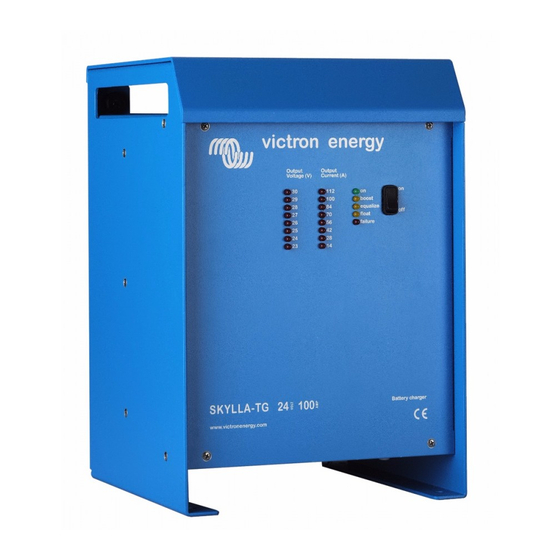
Operation Located on the front of the Skylla charger are an on/off switch and three rows of leds, as shown in illustration 5. The battery charger can be switched on and off with the on/off switch. The “output voltage” leds indicate the output voltage value. The “output current”... -
Page 15: Maintenance
After this time the charger will enter the float-charge mode and the “float” led will illuminate. After the batteries are charged the Skylla charger does not have to be switched off and the batteries can stay connected to the battery charger. Maintenance The Skylla charger does not require any specific maintenance. -
Page 16: Options
OPTIONS The Skylla charger is factory set to standard values. Some of these standard values can be changed by a qualified electrical technician into customised values. This chapter describes which values can be changed and how to change them. The cover of the Skylla may only be removed by a qualified technician. -
Page 17: Permanent Boost-Charge
In some cases, for example when the battery is almost empty, it is recommended to permanent boost-charge the battery for 10 hours. Do not permanently boost-charge sealed lead-acid batteries. Contact your Victron Energy dealer or battery dealer for more information on charging the battery. -
Page 18: Adjusting The Equalize-Charging Mode Time
8 hours 12 hours Diode-splitter charge voltage compensation. If a diode-splitter (Victron Energy Argo) is connected to the Skylla charger the charge voltage have to be raised to compensate for the voltage loss over the diode-splitter. If the voltage-sense option is used, do not use the diode-splitter compensation. -
Page 19: Traction Battery Compensation
Adjusted the output voltage to the desired voltage, see chapter 4.2. With the above mentioned procedure the output voltage range is limited. When the full output voltage range is required please contact your Victron Energy dealer. See chapter 6.3 for details. -
Page 20: Charging Batteries With Voltage Sensing
Charging batteries with voltage sensing Do not use the voltage sense facility in combination with the diode-splitter compensation, as this will raise the output voltage. When high current runs trough a thin cable between the charger and the battery there will be a voltage loss in the cables. -
Page 21: Connecting The Output Voltage Alarm
The maximum charging current of 30A, 50A or 100A, according to the model, can be limited with an external panel. This panel, the Victron Energy COV panel, contains an adjustable potentiometer. Limiting the maximum charging current can be useful to meet the batteries specifications, or to make sure the shore fuse does not blow. -
Page 22: Connecting A Remote On/Off Switch
To connect the panel: Disconnect the mains Connect the on led to the “L_ON” connector. Connect the ground of the panel to the “GND” connector. Connect the “TG switch” to the “REM” connector. The SKC panel: This panel indicates if the charger is on or off, it indicates the charging mode and it contains an adjustable potentiometer. -
Page 23: Connecting A Voltmeter
To connect the boost switch: Disconnect the mains. Connect one pole of the switch to the “RBOO” connector. Connect the other pole of the switch to the “GND” connector. 4.14 Connecting a voltmeter The remote-connector offers a possibility to connect a voltmeter. It is possible to connect a digital as well as an analogue voltmeter. -
Page 24: Fault Tracing
When a fault occurs in the battery charger, the following table can be used in order to find the fault. Before the Skylla is being checked, make sure that all the devices connected to the battery charger are removed. If the fault can not be solved, please contact your Victron Energy dealer. Problem Possible cause... -
Page 25: Technical Specifications
TECHNICAL SPECIFICATIONS General Switch on behaviour Charger can switch on under every load Temperature range 0 °C until +40 °C, decreasing output power if temperature > +40ºC According Council Directive 89/336 EEG Emission EN 55014 (1993) EN 61000-3-2 (1995) EN 61000-3-3 (1995) Immunity EN 55104 (1995) Vibration... -
Page 26: Output
Leakage current from battery when the battery charger is ≤ 3,2 mA ≤ 6,4 mA ≤ 6,4 mA turned off * 6,3mm x 32mm fuse 30A slow Contact your Victron Energy dealer for this option. Manual Skylla with universal input... -
Page 27: Mechanical
Mechanical TG24/30 and TG24/50 TG24/100 Cabinet Aluminium sea water resistant Aluminium sea water resistant Protection IP 21 IP 21 Colour Blue (RAL5012), epoxy coated Blue (RAL5012), epoxy coated Dimensions 368 x 250 x 257mm 365 x 250 x 147mm Dimensions 438 x 320 x 330mm 435 x 320 x 217mm including box... - Page 28 Ø 6 Ø 8 All measurements in mm. Pallas-TG 12/50, Skylla-TG 24/30, 24/30 110Vac drawing no.: TI010000 © victron energy b.v. date: 120204 Skylla -TG 24/50 and Titan 48/25 dimensions revision.: 0002 Manual Skylla with universal input...
- Page 29 Ø 6 Ø 8 All measurements in mm. drawing no.: TI020000 Skylla-TG 24/80, 24/100 and Titan 48/50 dimensions © victron energy b.v. date: 220703 revision.: 01 Manual Skylla with universal input...
- Page 30 Victron Energy B.V. The Netherlands Phone: +31 (0) 36 535 97 00 Fax: +31 (0) 36 531 16 66 E-mail: sales@victronenergy.com Internet site: http://www.victronenergy.com Version: rev03 Date: 16-02-2010 Manual Skylla with universal input...
Need help?
Do you have a question about the SKYLLA-TG 24/30 and is the answer not in the manual?
Questions and answers