Table of Contents
Advertisement
Quick Links
Advertisement
Table of Contents

Related Manuals for Omron Hornet 565


Summary of Contents for Omron Hornet 565
- Page 1 Hornet 565 Robot User’s Guide I596-E-03...
- Page 2 Copyright Notice The information contained herein is the property of Omron Adept Technologies, Inc., and shall not be reproduced in whole or in part without prior written approval of Omron Adept Technologies, Inc. The information herein is subject to change without notice and should not be construed as a commitment by Omron Adept Technologies, Inc.
- Page 3 Technical Specifications. Fixed rotation of tool flange in Fig. 5-2, added graphic for J4 alignment. July, Updated drawing of tool flange to show 41.14 mm pilot bore that was 2017 added since original release. Hornet 565 Robot User's Guide, 14608-000 Rev F Page 3 of 160...
-
Page 5: Table Of Contents
Chapter 3: Robot Installation 3.1 Transport and Storage 3.2 Unpacking and Inspecting the Hornet 565 Before Unpacking Upon Unpacking Unpacking 3.3 Repacking for Relocation 3.4 Environmental and Facility Requirements Hornet 565 Robot User's Guide, 14608-000 Rev F Page 5 of 160... - Page 6 Specifications for 24 VDC Robot and Controller Power Details for 24 VDC Mating Connector Procedure for Creating 24 VDC Cable Installing 24 VDC Robot Cable 4.7 Connecting 200-240 VAC Power to Robot Hornet 565 Robot User's Guide, User’s Guide, 14608-000 Rev F Page 6 of 160...
- Page 7 Verifying E-Stop Functions Aligning the Platform and J4 Motor Verify Robot Motions 5.8 Robot Motions Straight-line Motion Containment Obstacles 5.9 Learning to Program the Hornet 565 Hornet 565 Robot User's Guide, User’s Guide, 14608-000 Rev F Page 7 of 160...
- Page 8 Installing a Drive Shaft Aligning the Platform and J4 Motor 7.9 Replacing the Encoder Battery Pack 7.10 Non-Periodic Maintenance 7.11 Changing the Front Panel High-Power Indicator Lamp Hornet 565 Robot User's Guide, User’s Guide, 14608-000 Rev F Page 8 of 160...
- Page 9 Chapter 9: Environmental Concerns 9.1 Ambient Environment 9.2 Cleanroom Classification 9.3 Design Factors Robot Base and Components Inner Arms Ball Joints Outer Arms Spring Assemblies Platforms Hornet 565 Robot User's Guide, User’s Guide, 14608-000 Rev F Page 9 of 160...
-
Page 11: Chapter 1: Introduction
The Hornet 565 is available in two models. One has a J4 platform, a theta motor and theta drive shaft. This provides ±360° of rotation at the tool flange. The other model has a fixed plat- form with no tool flange rotation. -
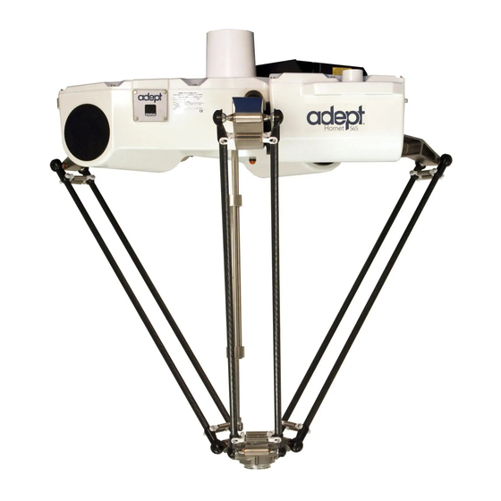
Page 12: Hornet 565 Base
Figure 1-2. eAIB Hornet 565 Base The Hornet 565 base is an aluminum casting that houses the four or three drive motors, and supports the eAIB. It provides three mounting pads for attaching the base to a rigid support frame. The Status Display panel is mounted on the side of the robot base. -
Page 13: Ball Joints, Outer Arms
Both platforms have a 38 mm hole through their center, for users to route air lines or electric cables to the tool flange. For the J4 version of the Hornet 565, a stainless steel theta drive shaft attaches to a U-joint at both the platform and the J4 motor on the robot. - Page 14 The J4 platform, which is rotational, is constructed such that the clocking, or rotational align- ment, of the platform relative to the robot base is critical. This is detailed in Aligning the Plat- form with the Base on page 29. Hornet 565 Robot User's Guide, 14608-000 Rev F Page 14 of 160...
-
Page 15: Smartcontroller Ex
You will need to connect the outer arms between the inner arms and the platform to reassemble the robot. The outer-arm assemblies are interchangeable. For the Hornet 565 with the J4 platform, you will also have to connect the telescoping drive shaft that connects the platform to the fourth motor on the robot base. -
Page 16: Installation Overview
Start the system, including system operation testing. Starting the System for the First Time on page 84. Install optional equipment, including end-effectors, Options on page 89. user air and electrical lines, external equipment, etc. Hornet 565 Robot User's Guide, 14608-000 Rev F Page 16 of 160... -
Page 17: How Can I Get Help
TEL: 81-75-344-7000 FAX: 81-75-344-7001 Related Manuals This manual covers the installation, operation, and maintenance of a Hornet 565 system. There are additional manuals that cover programming the system and adding optional com- ponents. See the following table. These manuals are available on the software media shipped with each system. -
Page 19: Chapter 2: Safety
Press any E-Stop button (a red push-button on a yellow background) and then follow the internal procedures of your company or organization for an emergency situation. Fire Response If a fire occurs, use CO to extinguish the fire. Hornet 565 Robot User's Guide, 14608-000 Rev F Page 19 of 160... -
Page 20: Entrapment And Brake Release Button
Guide, and must comply with all local and national safety regulations for the location in which the robot is installed. The Hornet 565 must not be used for purposes other than described in Intended Use of the Robots on page 21. Contact Customer Support if you are not sure of the suitability for your application. -
Page 21: Robot Behavior
2.4 Robot Behavior Hardstops If the Hornet 565 runs into one of its hardstops, the robot’s motion will stop completely, an envelope error will be generated, and power to the robot motors will be cut off. The robot cannot continue to move after hitting a hardstop until the error has been cleared. -
Page 22: Manufacturer's Declaration Of Incorporation
Chapter 2: Safety Manufacturer’s Declaration of Incorporation This lists all standards with which the robot complies. The Manufacturer’s Declarations for the Hornet 565 robot and other products are in the Manufacturer's Declarations Guide. Robot Safety Guide Robot Safety Guide provides detailed information on safety for our robots. It also gives resources for more information on relevant standards. -
Page 23: Chapter 3: Robot Installation
Unpacking The Hornet 565 is shipped in a crate that holds the robot base, outer arms, platform, theta drive shaft, and any accessories ordered. The crate is made of wood. The top of the crate should be removed first. - Page 24 2. Lift the top off of the crate sides, and set it aside. Figure 3-2. Crate, with Top Removed 3. Remove all cardboard boxes from inside the crate. These will include the outer arms, theta drive shaft, and platform. Hornet 565 Robot User's Guide, 14608-000 Rev F Page 24 of 160...
-
Page 25: Repacking For Relocation
Improper packaging for shipment will void your warranty. CAUTION: The robot must always be shipped in an upright orientation. 3.4 Environmental and Facility Requirements The Hornet 565 system installation must meet the operating environment requirements shown in the following table. Table 3-1. Robot System Operating Environment Requirements Ambient temperature 1 to 40°... -
Page 26: Robot-To-Frame Considerations
Chapter 3: Robot Installation The Hornet 565 is designed to be mounted above the work area suspended on a user-supplied frame. The frame must be adequately stiff to hold the robot rigidly in place while the robot plat- form moves within the workspace. -
Page 27: Mounting The Robot Base
CAUTION: Do not attempt to lift the robot from any points other than with slings as described here. Mounting Procedure The Hornet 565 has three mounting pads. Each pad has one hole with an M12 x 1.75 spring- ® lock Heli-Coil 1. -
Page 28: Install Mounting Hardware
Tighten the bolts to 61 N·m (45 ft-lb). NOTE: The robot base-mounting tabs have spring-lock Heli-Coils in the M12 holes, so lock washers are not needed on the M12 mounting bolts. Hornet 565 Robot User's Guide, 14608-000 Rev F Page 28 of 160... -
Page 29: Attaching The Outer Arms, Platform, And Theta Drive Shaft
Joints Tool Flange Figure 3-4. Major Robot Components The Hornet 565 platform is attached to the inner arms by the outer arms. NOTE: Except for attaching the outer arms and theta drive shaft, the platform is shipped fully-assembled. Aligning the Platform with the Base NOTE: The fixed platform is symmetrical, and can be mounted in any rotational... -
Page 30: Attaching The Outer Arms
One pair of outer arms attaches between each inner arm and the platform. No tools are needed. Each outer arm has a ball joint socket at each end. The inner arms and the platform have corresponding pairs of ball studs. Hornet 565 Robot User's Guide, 14608-000 Rev F Page 30 of 160... - Page 31 CAUTION: Ensure that the bearing insert is in place in the end of each outer arm. NOTE: In the following steps, take care not to trap debris between the ball studs and their sockets. Hornet 565 Robot User's Guide, 14608-000 Rev F Page 31 of 160...
- Page 32 Figure 3-8. Installing Ball Joints 2. Attach one pair of outer arms to each of the three pairs of ball studs on the platform. Hornet 565 Robot User's Guide, 14608-000 Rev F Page 32 of 160...
- Page 33 3. Ensure that all spring hooks are fully-seated in the grooves of the horseshoes, as shown in the following figure: Figure 3-9. Horseshoe and Spring Assembly Hornet 565 Robot User's Guide, 14608-000 Rev F Page 33 of 160...
-
Page 34: Attaching The Theta Drive Shaft
The hole in the side of the U-joint needs to line up with the hole in the shaft. Theta Drive Shaft U-Joint Screw J4 Shaft (Motor or Platform) Figure 3-10. U-Joint Hornet 565 Robot User's Guide, 14608-000 Rev F Page 34 of 160... -
Page 35: Mounting The Front Panel
A 6 mm diameter x 12 mm dowel pin (user-supplied) fits in a hole in the tool flange and can be used as a keying or anti-rotation device in a user-designed end-effector. Hornet 565 Robot User's Guide, 14608-000 Rev F Page 35 of 160... -
Page 36: Grounding
Ensure that lines going to the robot base do not block your view of the status LED. Ensure that lines going to the robot base do not interfere with the inner arm movement. Hornet 565 Robot User's Guide, 14608-000 Rev F Page 36 of 160... - Page 37 Must be considered as part of the payload, if they add weight to the platform or outer arms. Are the user’s responsibility for maintenance. They are not covered in the Maintenance section of this manual. Hornet 565 Robot User's Guide, 14608-000 Rev F Page 37 of 160...
-
Page 39: Chapter 4: System Installation
PLC Option Switch running ACE Software Figure 4-1. System Cable Diagram, without SmartController EX (eAIB Only) NOTE: See System Installation on page 39 for additional information on system grounding. Hornet 565 Robot User's Guide, 14608-000 Rev F Page 39 of 160... -
Page 40: List Of Cables And Parts
WARNING: The XUSR, XMCP, and XFP jumpers intentionally bypass safety connections so you can test the system functionality during setup. Under no cir- cumstances should you run a Hornet 565 system, in production mode, with all three jumpers installed. This would leave the system with no E-Stops. -
Page 41: Cable Installation Overview
Chapter 4: System Installation Cable Installation Overview Power requirements for the SmartVision MX industrial PC are covered in that user guide. For 24 VDC, both the Hornet 565 and a SmartVision MX can usually be powered by the same power supply. Step... -
Page 42: Optional Cables
The XIO Breakout cable is for using the I/O on the eAIB. See XIO Breakout Cable on page 82. Cables for adding belt encoders are covered in System Cables for Systems with Belt Encoders on page 46. Hornet 565 Robot User's Guide, 14608-000 Rev F Page 42 of 160... -
Page 43: System Cables, With Smartcontroller Ex
1. Mount the SmartController EX and optional front panel. 2. Connect the optional front panel to the SmartController EX. 3. Connect the optional pendant to the SmartController EX. Hornet 565 Robot User's Guide, 14608-000 Rev F Page 43 of 160... -
Page 44: List Of Cables And Parts
The XUSR, XMCP, and XFP jumpers intentionally bypass safety connections so you can test the system functionality during setup. WARNING: Under no circumstances should you run a Hornet 565 system, in production mode, with all three jumpers installed. This would leave the system with no E-Stops. -
Page 45: Cable Installation Overview
XIO Breakout Cable, 12 inputs/8 outputs, 5 M Available as option Y Cable, for XSYS cable connections to dual robots Available as option with SmartController EX eAIB XBELT IO Adapter Cable Available as option Hornet 565 Robot User's Guide, 14608-000 Rev F Page 45 of 160... -
Page 46: System Cables For Systems With Belt Encoders
The optional eAIB XBELT IO Adapter cable splits the eAIB XBELTIO port into a belt encoder lead, an Intelligent Force Sensor or IO Blox lead, and an RS-232 lead. Hornet 565 Robot User's Guide, 14608-000 Rev F Page 46 of 160... -
Page 47: Cable Installation Overview
Connect T20 adapter cable to eAIB XSYSTEM cable XMCP connector or J, K if no T20, install XMCP jumper T20 Adapter Cable with T20 bypass plug. Connect user-supplied ground to robot. See Grounding the Hornet 565 on page Hornet 565 Robot User's Guide, 14608-000 Rev F Page 47 of 160... -
Page 48: Pinouts For Eaib Xbelt Io Adapter
HDB26 - PIN 1 BELT_5V BELT ENC - PIN 12 HDB26 - PIN 10 BELT ENC - SHELL HDB26 - SHELL SHIELD RS232 – – – – FORCE/EXPIO – – – Hornet 565 Robot User's Guide, 14608-000 Rev F Page 48 of 160... -
Page 49: Ace Software
6. After closing the ACE Setup wizard, click Exit on the disk menu to close the menu. NOTE: You will have to restart the PC after installing ACE software. Hornet 565 Robot User's Guide, 14608-000 Rev F Page 49 of 160... -
Page 50: Robot Interface Panel
XUSR), or an eAIB XSYS cable, if connecting to a SmartController EX. ENET - Two Ethernet ports are available. One will be needed to connect to a PC running ACE software. Hornet 565 Robot User's Guide, 14608-000 Rev F Page 50 of 160... -
Page 51: Connecting 24 Vdc Power To Robot
DIN-Rail Mount Details for 24 VDC Mating Connector The 24 VDC mating connector and two pins are supplied with each system. They are shipped in the cable/accessories box. Hornet 565 Robot User's Guide, 14608-000 Rev F Page 51 of 160... -
Page 52: Procedure For Creating 24 Vdc Cable
2. Plug the mating connector end of the 24 VDC cable into the 24 VDC connector on the interface panel of the eAIB, which is on top of the robot. 3. Connect the cable shield to the ground point on the interface panel. Hornet 565 Robot User's Guide, 14608-000 Rev F Page 52 of 160... -
Page 53: Connecting 200-240 Vac Power To Robot
National Electrical Code and any local codes. Ensure compliance with all local and national safety and electrical codes for the installation and operation of the robot system. Hornet 565 Robot User's Guide, 14608-000 Rev F Page 53 of 160... -
Page 54: Specifications For Ac Power
Specifications are established at nominal line voltage. Low line voltage can affect robot performance. NOTE: The Hornet 565 robot is intended to be installed as a piece of equipment in a permanently-installed system. NOTE: If a three-phase power source is used, it must be symmetrically-earthed (with grounded neutral). - Page 55 L = Line 1 565 Robot N = Line 2 1Ø 200–240 VAC E = Earth Ground Figure 4-7. Single-Phase Load across L1 and L2 of a Three-Phase Supply Hornet 565 Robot User's Guide, 14608-000 Rev F Page 55 of 160...
-
Page 56: Details For Ac Mating Connector
9. Reinstall the cover and tighten the screw to secure the connector. 10. Prepare the opposite end of the cable for connection to the facility AC power source. Hornet 565 Robot User's Guide, 14608-000 Rev F Page 56 of 160... -
Page 57: Installing Ac Power Cable To Robot
If there will be hazardous voltages present at the tool flange or end-effector, you must: Connect the mounting frame to protective earth ground. Ground the robot base to the mounting frame. Hornet 565 Robot User's Guide, 14608-000 Rev F Page 57 of 160... -
Page 58: Grounding Robot Base To Frame
If the frame is not painted where the M12 screw makes contact with it, you do not need to use a ring terminal, just put an external-tooth star washer under the mounting screw head. Hornet 565 Robot User's Guide, 14608-000 Rev F Page 58 of 160... -
Page 59: Installing User-Supplied Safety Equipment
User E-Stop CH 1 (mushroom push- N/C contacts, Shorted if NOT Used button, safety gates, etc.) 2, 15 User E-Stop CH 2 (same as pins N/C contacts, Shorted if NOT Used Hornet 565 Robot User's Guide, 14608-000 Rev F Page 59 of 160... - Page 60 6, 19 Muted Safety Gate CH 2 (same as N/C contacts, Shorted if NOT Used pins 5, 18) Voltage-Free Contacts provided by the Hornet 565 System 7, 20 E-Stop indication CH 1 Contacts are closed when Front Panel, pendant, and customer E-Stops are not...
- Page 61 24 V No connection The following figure shows an E-Stop diagram for the system. See System Installation on page 39 for a description of the functionality of this circuit. Hornet 565 Robot User's Guide, 14608-000 Rev F Page 61 of 160...
- Page 62 Cyclic Check Output Control Circuit XSYSTEM-25 (XUSR-20) XSYSTEM-40 (XUSR-21) Single-Phase High Power to AC Input Amplifiers 200-240 VAC (Internal Connections) Figure 4-11. E-Stop Circuit on XUSR and XFP Connectors Hornet 565 Robot User's Guide, 14608-000 Rev F Page 62 of 160...
-
Page 63: Emergency Stop Circuits
These contacts provide a method to indicate the status of the ESTOP chain, inclusive of the Front Panel Emergency Stop push-button, the pendant Emergency Stop push-button, and the User Emergency Stop Contacts. Hornet 565 Robot User's Guide, 14608-000 Rev F Page 63 of 160... - Page 64 CAUTION: If you want the cell gate to always cause a robot shutdown, wire the gate switch contacts in series with the user E-Stop inputs. Do not wire the gate switch into the muted safety gate inputs. Hornet 565 Robot User's Guide, 14608-000 Rev F Page 64 of 160...
-
Page 65: Remote Manual Mode
See the Front Panel schematic (Front Panel Schematic on page 63) for details of the Front Panel’s wiring. In Hornet 565 Robot User's Guide, 14608-000 Rev F Page 65 of 160... -
Page 66: High Power On/Off Lamp
The extension cable must conform to the following specifications: Wire Size: must be larger than 26 AWG. Connectors: must be 15-pin, standard D-sub male and female. Maximum cable length is 10 meters. Hornet 565 Robot User's Guide, 14608-000 Rev F Page 66 of 160... -
Page 67: Remote Pendant Usage
Connectors: must be 15-pin, standard D-sub male and female. Maximum cable length is 10 meters. CAUTION: Do not modify the cable that is attached to the pendant. This could cause unpredictable behavior from the robot system. Hornet 565 Robot User's Guide, 14608-000 Rev F Page 67 of 160... -
Page 69: Chapter 5: System Operation
Fault Code(s) Fault, see Status Display Amber, Slow Blink Selected Configuration Node Amber, Fast Blink Fault Code(s) Fault, see Status Display See Status Panel Fault Codes on page 70. Hornet 565 Robot User's Guide, 14608-000 Rev F Page 69 of 160... -
Page 70: Status Panel Fault Codes
This braking system does not prevent you from moving the robot manually, once the robot has stopped (and high power has been disabled). Hornet 565 Robot User's Guide, 14608-000 Rev F Page 70 of 160... -
Page 71: Brake-Release Button
You can also configure the XIO Input 6.2 (pin 18) to act as an alternate hardware brake release input. The setting is available on the Robot page in the ACE software. The parameter is Hornet 565 Robot User's Guide, 14608-000 Rev F Page 71 of 160... -
Page 72: Optional Front Panel
Manual mode initiates software restrictions on robot speed, commanding no more than 250 mm/sec. There is no high speed mode in manual mode. Hornet 565 Robot User's Guide, 14608-000 Rev F Page 72 of 160... - Page 73 NOTE: A Front Panel or equivalent circuits must be installed to be able to Enable Power to the robot. To operate without the standard Front Panel, the user must sup- ply the equivalent circuits. Hornet 565 Robot User's Guide, 14608-000 Rev F Page 73 of 160...
-
Page 74: Connecting Digital I/O To The System
8 outputs User’s Guide Optional sDIO Module, 32 inputs, 32 outputs see the SmartController EX connects to SmartController EX per module; up to four User’s Guide sDIO per system Hornet 565 Robot User's Guide, 14608-000 Rev F Page 74 of 160... - Page 75 IO Blox 8 Output signals: 0105 to 0112 12 Input signals: 1097 to 1105 Device 8 Output signals: 0097 to 0104 Figure 5-4. Connecting Digital I/O to the System Hornet 565 Robot User's Guide, 14608-000 Rev F Page 75 of 160...
-
Page 76: Using Digital I/O On Eaib Xio Connector
These signals can be used by eV+ to perform various functions in the workcell. See the following table for the XIO signal designations. 12 Inputs, signals 1097 to 1108 8 Outputs, signals 0097 to 0104 Brake Release and LED Light Hornet 565 Robot User's Guide, 14608-000 Rev F Page 76 of 160... - Page 77 Input 1.2 1103 Pin 1 Input 2.2 1104 XIO 26-pin female connector on Robot Input 3.2 1105 Interface Panel Input 4.2 1106 Input 5.2 1107 Input 6.2 1108 Hornet 565 Robot User's Guide, 14608-000 Rev F Page 77 of 160...
-
Page 78: Optional I/O Products
With a SmartController EX, you can only use the EX XDIO inputs. With a Hornet robot without a SmartController EX, you can only use the XIO inputs. See the eV+ Language User’s Guide for information on digital I/O programming. Hornet 565 Robot User's Guide, 14608-000 Rev F Page 78 of 160... - Page 79 Software scan rate/response time 16 ms scan cycle/ 32 ms max response time NOTE: The input current specifications are provided for reference. Voltage sources are typically used to drive the inputs. Hornet 565 Robot User's Guide, 14608-000 Rev F Page 79 of 160...
-
Page 80: Xio Output Signals
In the event of an output short or other overcurrent situation, the affected output of the driver IC turns off and back on automatically to reduce the temperature of the IC. The Hornet 565 Robot User's Guide, 14608-000 Rev F Page 80 of 160... - Page 81 ≤ (+V - 45) demag Load = 1 mH) DC short circuit current limit 0.7 A ≤ I ≤ 2.5 A Peak short circuit current ≤ 4 A ovpk Hornet 565 Robot User's Guide, 14608-000 Rev F Page 81 of 160...
-
Page 82: Xio Breakout Cable
The cable length is 5 M (16.4 ft). See the following table for the cable wire chart. NOTE: This cable is not compatible with the XIO Termination Block. Figure 5-7. Optional XIO Breakout Cable Hornet 565 Robot User's Guide, 14608-000 Rev F Page 82 of 160... - Page 83 Pink Output 2 Pink/Black Output 3 Light Blue Output 4 Light Blue/Black Output 5 Light Green Output 6 Light Green/Black Output 7 White/Red Output 8 White/Blue Shell Shield Hornet 565 Robot User's Guide, 14608-000 Rev F Page 83 of 160...
-
Page 84: Starting The System For The First Time
XUSR to the XSYSTEM on the eAIB, or XUSR port on a SmartController EX, or XUSR jumper installed. User-supplied 200/240 VAC power to the robot 200/240 VAC connector. Hornet 565 Robot User's Guide, 14608-000 Rev F Page 84 of 160... -
Page 85: Turning On Power And Starting Ace
Start > Programs > Omron > ACE <major>.<minor> 5. On the ACE Getting Started screen: Select Create New Workspace for Selected Controller to make the connection to the controller. Hornet 565 Robot User's Guide, 14608-000 Rev F Page 85 of 160... -
Page 86: Enabling High Power
J4 motor, you need to use the ACE software to estab- lish this alignment. 1. Within the ACE software, open the Hornet565 robot object. 2. In the Configure tab, click Adjust J4 Zero. Hornet 565 Robot User's Guide, 14608-000 Rev F Page 86 of 160... -
Page 87: Verify Robot Motions
User’s Guide for complete instructions on using the pendant. The Hornet 565 is a parallel-arm robot and, as such, individual joint motions are not allowed. If you attempt to move a joint in Joint mode, you will get an error message: JOINT <n>... -
Page 88: Robot Motions
5.8 Robot Motions Straight-line Motion Joint-interpolated motion is not possible with the Hornet 565, because the positions of all the joints must always be coordinated in order to maintain the connections to the moving plat- form. Therefore, for the Hornet 565, the eV+ system automatically performs a straight-line motion when a joint-interpolated motion instruction is encountered. -
Page 89: Chapter 6: Options
To ensure that ball joints do not separate under extreme use. 6.1 Tall Frame Adapters The Hornet 565 can be mounted in a tall frame, previously used for a competitive parallel robot, by installing a set of three frame adapters. -
Page 90: Eplc Connect
Chapter 6: Options 6.2 ePLC Connect The Hornet 565 can use a user-supplied PLC, with the ePLC Connect software, to control the robot motions. Refer to ePLC Connect 3 User’s Guide. Hornet 565s that use a PLC, but do not use a SmartController EX, rely on the user-supplied PLC for all digital I/O. - Page 91 4. You can change the IP address and subnet mask in the Desired Address and Desired Subnet fields, if needed. 5. Click OK. The ACE software will ask you to wait for the controller to reboot. Hornet 565 Robot User's Guide, 14608-000 Rev F Page 91 of 160...
-
Page 92: Configuring The Omron Plc
The SmartVision MX is a Windows 7 Embedded industrial PC designed to run the ACE soft- ware. It is compatible with the Hornet 565, with or without the SmartController EX motion con- troller. For inspection applications, the SmartVision MX industrial PC is designed to be a “plug-and- play”... -
Page 93: Cable Inlet Box
Cable Exit from Rear of Box (Mounting Surface) Figure 6-3. Cable Inlet Box Mounted on a Hornet 565 NOTE: The cable inlet box is not USDA compliant. Drainage of wash-down from the cable seal assembly does not comply with USDA requirements. -
Page 94: Installation Procedure
See the following figure, right photograph. Ensure that the gasket is seated between the eAIB surface and the cable seal housing. Hornet 565 Robot User's Guide, 14608-000 Rev F Page 94 of 160... - Page 95 Chapter 6: Options Figure 6-4. Cable Seal Housing (left), Installed (right, AIB shown) Figure 6-5. Cable Entry Top Cover Assembly Figure 6-6. Bottom of Cable Entry Top Cover, CF Frame Hornet 565 Robot User's Guide, 14608-000 Rev F Page 95 of 160...
- Page 96 See the following figure. Ensure that the terminated cable ends have 10 - 12 in. of slack. See Figure 6-11. Figure 6-9. Installing Roxtec Modules into the Frame Hornet 565 Robot User's Guide, 14608-000 Rev F Page 96 of 160...
- Page 97 8. Attach the ground lug to GND on the eAIB. The ground lug is for the cable shield of the user-supplied 24 VDC cable. See the following figure. Hornet 565 Robot User's Guide, 14608-000 Rev F Page 97 of 160...
- Page 98 Ensure that the gasket between the top cover and the cable seal housing is seated, and that all cables are contained within the top cover. Lower the top cover onto the seal housing, and secure with one screw. Hornet 565 Robot User's Guide, 14608-000 Rev F Page 98 of 160...
-
Page 99: Intelligent Force Sensor
The ball stud lock consists of slightly more than a half-circle of hard plastic that slides over the end of the ball joint socket. They can be installed and removed without tools. See the fol- lowing figures. Hornet 565 Robot User's Guide, 14608-000 Rev F Page 99 of 160... -
Page 100: Installing A Ball Stud Lock
The lock is designed to be tight enough that it will not come off in use. No tools are needed. 2. Twist the ball stud lock back-and-forth slightly, after installation, to ensure that it is fully seated. Hornet 565 Robot User's Guide, 14608-000 Rev F Page 100 of 160... -
Page 101: Removing A Ball Stud Lock
To remove a ball stud lock, pull one end of the lock away from the ball joint socket. The lock will slide off (with resistance). No tools are needed. Figure 6-17. Removing a Ball Stud Lock Hornet 565 Robot User's Guide, 14608-000 Rev F Page 101 of 160... -
Page 103: Chapter 7: Maintenance
7.1 Cleaning Water Shedding Surfaces of the Hornet 565 have been designed to shed water. This increases the likelihood that contaminants or cleaning agents will drain with a wash-down procedure. Wash-Down Wash-down cleaning is appropriate for cleaning the Hornet 565. Surfaces and joints have been designed with smooth internal radii for easy cleaning. -
Page 104: Chemical Compatibility
Caustic The Hornet 565 is designed to be compatible with moderate cleaning agents commonly used in the cleaning of food-processing equipment, at room temperature. All robot components are designed to handle daily exposure to cleaning agents. Exposure may result in some dis- coloration of the materials, but no significant material removal. - Page 105 Replace gaskets. Inlet Box ible, broken gaskets. gaskets Status 3 Mon Check for water inside the display. Replace seal. Display Check for good seal contact, inflexible, Panel broken, seal. Hornet 565 Robot User's Guide, 14608-000 Rev F Page 105 of 160...
-
Page 106: Checking Labels
Figure 7-1. Read User’s Guide, Impact Warning Label This label is located near the status display on the Hornet body. Hornet 565 Robot User's Guide, 14608-000 Rev F Page 106 of 160... -
Page 107: Informative Labels
This label is located next to the brake release button and brake release button label. Informative Labels Brake Release Label, 18265-000 This label identifies the brake release button on the underside of the Hornet 565. It is a ring that surrounds the brake release button. 7.4 Checking Safety Systems These tests should be performed every six months. -
Page 108: Checking Robot Mounting Bolts
WARNING: Remove all power to the robot before opening the eAIB chassis. The Hornet 565 uses gear drives, which use oil in their components for lubrication. Peri- odically inspect the robot for signs of oil on and around the gear drives. -
Page 109: Checking Fan Operation
5. Check the outside of the motors and gear drives for any signs of oil. 6. Contact your local Omron Support if you find any signs of oil in these areas. If you aren’t going to check the operation of the motor fans: 7. -
Page 110: Theta Drive Shaft
Torque the bolts to 1.1 N·m (10 in-lb). 7.8 Theta Drive Shaft NOTE: The fixed platform Hornet 565 does not use a theta drive shaft, so the fol- lowing procedures do not apply to those robots. Replacing the Drive Shaft Bushings The bushings in the drive shaft are a normal wear item, and need to be replaced yearly or every 5,000 hours of use. - Page 111 5. Remove the center shaft from the drive shaft cylinder. Retain the center shaft for reassembly. 6. The upper end of the center shaft has a fixture that holds three bushings. These Hornet 565 Robot User's Guide, 14608-000 Rev F Page 111 of 160...
- Page 112 You will need to “feel” for the bushings lining up with their guides inside the cylinder. 10. Slide the replacement bottom end cap over the end of the center shaft. Hornet 565 Robot User's Guide, 14608-000 Rev F Page 112 of 160...
-
Page 113: Removing The Drive Shaft
J4 platform. Disconnect the bottom U-joint from the shaft on top of the J4 platform. Disconnect the top U-joint from the drive shaft of the J4 motor. Hornet 565 Robot User's Guide, 14608-000 Rev F Page 113 of 160... -
Page 114: Installing A Drive Shaft
Lower U-Joint 2. Insert one of the M6 x 20 dog point set screws pre- at J4 Platform viously removed through the hole in the side of the U- Hornet 565 Robot User's Guide, 14608-000 Rev F Page 114 of 160... -
Page 115: Aligning The Platform And J4 Motor
This will launch a utility for aligning the theta drive shaft. 3. Follow the instructions in the utility. Contact your local Omron Support for more information on this procedure. NOTE: Once the theta drive shaft is installed, the J4 motor and the tool flange will always rotate together, so the software will know the orientation of the tool flange. - Page 116 See the following figure. CAUTION: If battery power is removed from the robot, factory cal- ibration data may be lost, requiring robot recalibration by your local Omron Support personnel. Hornet 565 Robot User's Guide, 14608-000 Rev F Page 116 of 160...
- Page 117 NOTE: In the preceding figure, the diag cable has not yet been attached to the battery bracket. 14. Re-install the Status Display panel with the four M4 bolts previously removed. Hornet 565 Robot User's Guide, 14608-000 Rev F Page 117 of 160...
-
Page 118: Non-Periodic Maintenance
1. Turn off system power to the robot. 2. Turn off power to the optional SmartController EX, if you are using one. 3. Disconnect the cable between the Front Panel and the eAIB (or controller). Hornet 565 Robot User's Guide, 14608-000 Rev F Page 118 of 160... - Page 119 Front Panel. Be careful when separating front cover from body to avoid High Power On/Off damaging the wires. Lamp Body Figure 7-10. Lamp Body Contact Alignment Hornet 565 Robot User's Guide, 14608-000 Rev F Page 119 of 160...
-
Page 120: Replacing A Platform
NOTE: It is unlikely that you will ever need to remove the components of the outer arm spring assemblies. Removing Outer Arm Springs 1. Bend the spring so that the end is 90° from normal. See the following figure. Hornet 565 Robot User's Guide, 14608-000 Rev F Page 120 of 160... - Page 121 2. Slip the springs off of the horseshoes. See the following figure. Figure 7-12. Spring, with End Removed from Horseshoe The narrowest part of the horseshoe is 90° from the groove in which the spring Hornet 565 Robot User's Guide, 14608-000 Rev F Page 121 of 160...
- Page 122 2. Pull the loose end of the horseshoe (spreading it slightly), and slip the end on top of the other outer arm pin. The horseshoes are very stiff, and do not bend easily. See the following figure. Hornet 565 Robot User's Guide, 14608-000 Rev F Page 122 of 160...
- Page 123 2. Repeat for the remaining spring. Installing the last spring is the most difficult, as the other spring will tend to keep the spring from moving. Hornet 565 Robot User's Guide, 14608-000 Rev F Page 123 of 160...
-
Page 124: Replacing The Eaib Chassis
7. Disconnect any other cables, which may be connected to the chassis, such as XIO, RS- 232, 1394, or any others. Figure 7-16. eAIB on Hornet 565 Base Hornet 565 Robot User's Guide, 14608-000 Rev F Page 124 of 160... - Page 125 The chassis can be laid flat on its cooling fins. CAUTION: The eAIB can damage the O-ring that seals it if you are not careful. Ensure that nothing scrapes against the O-ring. Hornet 565 Robot User's Guide, 14608-000 Rev F Page 125 of 160...
- Page 126 Chapter 7: Maintenance Figure 7-18. Opening Chassis 10. Disconnect the “white” amplifier cable from the amplifier connector located on the chassis bracket. See the following figure. Hornet 565 Robot User's Guide, 14608-000 Rev F Page 126 of 160...
- Page 127 12. Using a 5 mm hex wrench, disconnect and remove the ground wire from the chassis. Keep the screw for reassembly later. See the following figures. Figure 7-20. Ground Screw Hole on eAIB Chassis Hornet 565 Robot User's Guide, 14608-000 Rev F Page 127 of 160...
-
Page 128: Installing A New Eaib Chassis
In rare cases with a new robot with an eAIB, you may need to commission the system. If the system will not power up, and the robot status display shows SE, you need to commission the system. Hornet 565 Robot User's Guide, 14608-000 Rev F Page 128 of 160... -
Page 129: Safety Commissioning Utilities
Prerequisites The robot must be set up and functional. ACE software must be installed. If using a factory-supplied Front Panel, the keyswitch must be in Auto mode. Hornet 565 Robot User's Guide, 14608-000 Rev F Page 129 of 160... -
Page 130: E-Stop Configuration Utility
This utility sets the E-Stop hardware delay to factory specifications. NOTE: Ensure that the commissioning jumper is plugged into the XBELTIO jack on the eAIB before you start this procedure. Procedure From within the ACE software: Hornet 565 Robot User's Guide, 14608-000 Rev F Page 130 of 160... -
Page 131: E-Stop Verification Utility
NOTE: This procedure takes 2 or 3 minutes to complete. From within the ACE software: 1. Open the robot object editor. 2. Select Configure > Safety Settings > Configure Teach Restrict, then click Next. Hornet 565 Robot User's Guide, 14608-000 Rev F Page 131 of 160... -
Page 132: Teach Restrict Verification Utility
The default speed is 10, but you can change that speed with this screen's speed control. You can click Move to Ready, to move the robot to the Ready position. Hornet 565 Robot User's Guide, 14608-000 Rev F Page 132 of 160... - Page 133 This indicates that the Teach Restrict function is working. 4. Click Next. The results of the verification will be displayed. 5. Click Finish. 6. Reset the Front Panel keyswitch to Auto mode. Hornet 565 Robot User's Guide, 14608-000 Rev F Page 133 of 160...
-
Page 135: Chapter 8: Technical Specifications
Joint 4 3x Ø 42.84 +0.03 M12 x 1.75 3x Ø 24 0.00 Ø 0.2 5 ±0.1 Section A-A 36° Units are mm Joint 1 Figure 8-1. Mounting Dimensions Hornet 565 Robot User's Guide, 14608-000 Rev F Page 135 of 160... - Page 136 Ensure that the bolts used to attach end-effectors engage the threads in the tool flange suf- ficiently. The engagement needs to be between 8 and 11 mm (0.3 and 0.4 in.). Hornet 565 Robot User's Guide, 14608-000 Rev F Page 136 of 160...
- Page 137 3x 226 Robot Mount Surface 3x 168 Arm travel volume (See CAD model for all dimensions) Units are mm Figure 8-4. Arm Travel Volume Hornet 565 Robot User's Guide, 14608-000 Rev F Page 137 of 160...
- Page 138 Cut-out 3x R25 3x 120° 6x R13 3x 72 3x 143 36° Units are mm Figure 8-5. Flat Plate Dimensions Flat Plate Figure 8-6. Flat Plate Iso View Hornet 565 Robot User's Guide, 14608-000 Rev F Page 138 of 160...
-
Page 139: Robot Specifications
1 to +40° C (34 to 104° F) Humidity 5% to 90%, non-condensing Shipping and Storage Temperature -25 to 60° C (-13 to 140° F) Humidity 75% or less, non-condensing Hornet 565 Robot User's Guide, 14608-000 Rev F Page 139 of 160... -
Page 140: Payload Specifications
Maximum rotation: ±360°, J4 platform NOTE: The fixed platform does not rotate. NOTE: Take care not to exceed the tool flange torque limits. Excessive torque can cause permanent misalignment of the tool flange. Hornet 565 Robot User's Guide, 14608-000 Rev F Page 140 of 160... -
Page 141: Performance
Adept cycle - 25-305-25 mm, 1 kg, no rotation 1 kg, no rotation 1160 0.37 sec. Long Vertical Strokes - 410 mm, 3 kg, 90° rotation 3 kg, 90° rotation 1630 0.41 sec. Hornet 565 Robot User's Guide, 14608-000 Rev F Page 141 of 160... -
Page 142: Stopping Time And Distance
X Stopping Distance (Hornet565 J4) Payload 33% Vmax 5.9m/s Payload 66% Vmax 5.8m/s Payload 100% Vmax 5.7m/s Speed (%) Figure 8-7. Hornet 565 X Stopping Distance with J4 Platform X Stopping Time (Hornet565 J4) 0.15 Payload 33% Vmax 0.10 5.9m/s Payload 66% Vmax 5.8m/s Payload 100% 0.05... - Page 143 Y Stopping Distance (Hornet565 J4) Payload 33% Vmax 5.9m/s Payload 66% Vmax 5.8m/s Payload 100% Vmax 5.7m/s Speed (%) Figure 8-9. Hornet 565 Y Stopping Distance with J4 Platform Y Stopping Time (Hornet565 J4) 0.15 Payload 33% Vmax 0.10 5.9m/s Payload 66% Vmax 5.8m/s Payload 100% 0.05...
- Page 144 Z Stopping Distance (Hornet565 J4) Payload 33% Vmax 3.5m/s Payload 66% Vmax 3.5m/s Payload 100% Vmax 3.5m/s Speed (%) Figure 8-11. Hornet 565 Z Stopping Distance with J4 Platform Z Stopping Time (Hornet565 J4) 0.15 Payload 33% Vmax 0.10 3.5m/s Payload 66% Vmax 3.5m/s Payload 100% 0.05...
- Page 145 X Stopping Distance (Hornet565 Fixed) Payload 33% Vmax 5.7m/s Payload 66% Vmax 5.2m/s Payload 100% Vmax 5m/s Speed (%) Figure 8-13. Hornet 565 X Stopping Distance with Fixed Platform X Stopping Time (Hornet565 Fixed) 0.15 Payload 33% Vmax 0.10 5.7m/s Payload 66% Vmax 5.2m/s Payload 100% 0.05...
- Page 146 Y Stopping Distance (Hornet565 Fixed) Payload 33% Vmax 5.7m/s Payload 66% Vmax 5.2m/s Payload 100% Vmax 5m/s Speed (%) Figure 8-15. Hornet 565 Y Stopping Distance with Fixed Platform Y Stopping Time (Hornet565 Fixed) 0.15 Payload 33% Vmax 0.10 5.7m/s Payload 66% Vmax 5.2m/s Payload 100% 0.05...
- Page 147 Z Stopping Distance (Hornet565 Fixed) Payload 33% Vmax 3.4m/s Payload 66% Vmax 3.3m/s Payload 100% Vmax 3.3m/s Speed (%) Figure 8-17. Hornet 565 Z Stopping Distance with Fixed Platform Z Stopping Time (Hornet565 J4) 0.15 Payload 33% Vmax 0.10 3.5m/s Payload 66% Vmax 3.5m/s Payload 100% 0.05...
-
Page 148: Payload Mass Vs. Acceleration
Fixed Fixed 10.0 11.0 % is the eV+ Accel/Decel setting, which, for the Hornet 565, can be set as high as 750%. Payload Inertia vs. Acceleration The following table provides a general guideline based on typical high-performance use. The practical inertia for any application will vary depending on the performance requirements. -
Page 149: Robot Mounting Frame
Chapter 8: Technical Specifications 8.6 Robot Mounting Frame The Hornet 565 is designed to be mounted above the work area, suspended from a user-sup- plied frame. The frame must be adequately stiff to hold the robot rigidly in place while the robot platform moves around the workspace. - Page 150 Gusset, 9.5 [.38] Thick See detail Tube, Square, Steel, 80 x 80 x 6.3 Mounting Bracket 1 See detail Mounting Bracket 2 See detail Mounting Bracket 3 See detail Hornet 565 Robot User's Guide, 14608-000 Rev F Page 150 of 160...
- Page 151 [32.17] [32.17] 25.4 [1.00] Sections shown in next figure. Figure 8-20. Mounting Frame, Side View 1 Sections A, B, C, and D are shown in the following figure. Hornet 565 Robot User's Guide, 14608-000 Rev F Page 151 of 160...
- Page 152 [4.09] [1.00] THRU 73.7 9.84 [2.90] [7.09] Detail of Item 9 [3.94] Detail of Item 8 Detail of Item 4 Figure 8-22. Mounting Frame, Details Items 4-5, 7-10 Hornet 565 Robot User's Guide, 14608-000 Rev F Page 152 of 160...
- Page 153 15.4 [0.60] 15.3 [0.60] 43.4 [1.71] 12.7 43.3 [1.71] 12.7 [0.50] [0.50] Detail of Item 12 Detail of Item 13 Figure 8-23. Mounting Frame, Detail Items 12 & 13 Hornet 565 Robot User's Guide, 14608-000 Rev F Page 153 of 160...
- Page 154 [1.00] R 21.4 [0.84] 30° Ø 15 THRU [0.59] 63.5 [2.50] 15.4 [0.61] 12.7 43.5 [1.71] [0.50] Detail of Item 14 Figure 8-24. Mounting Frame, Detail Item 14 Hornet 565 Robot User's Guide, 14608-000 Rev F Page 154 of 160...
-
Page 155: Chapter 9: Environmental Concerns
The rest of this chapter applies to the Hornet 565, not to the SmartController. The Hornet 565 is designed to be compatible with standard cleaning and operational needs for the handling of food products, as well as less stringent requirements. These design criteria impact how the environment can affect the robot operations, as well as how the robot can affect the cleanliness of its operating environment. -
Page 156: Robot Base And Components
The inserts generally produce few wear particulates. The material used in the inserts is FDA-compliant. Lubrication of the ball joints is not needed. Refer to Chemical Compatibility on page 104. Contact your local Omron Support for more information. Outer Arms The outer arms are a composite assembly of carbon fiber and black anodized aluminum. -
Page 157: Spring Assemblies
Platforms The Hornet 565 supports two types of platforms. The J4 platform is electroless-nickel-plated aluminum. The fixed platform is made of stainless steel. Both platforms are designed to meet IP67 and the basic criteria of wash-down compatibility and long life. - Page 160 OMRON ADEPT TECHNOLOGIES, INC. No. 438A Alexandra Road # 05-05/08 (Lobby 2), 4550 Norris Canyon Road, Suite 150, San Ramon, CA 94583 U.S.A. © OMRON Corporation 2017 All Rights Reserved. Alexandra Technopark, Tel: (1) 925-245-3400/Fax: (1) 925-960-0590 In the interest of product improvement,...
Need help?
Do you have a question about the Hornet 565 and is the answer not in the manual?
Questions and answers