Table of Contents
Advertisement
Quick Links
Advertisement
Table of Contents

Related Manuals for Omron iX3 565


Summary of Contents for Omron iX3 565
- Page 1 iX3 Robot with EtherCAT User's Manual I655-E-01...
- Page 2 The information contained herein is the property of OMRON Robotics and Safety Technologies, Inc., and shall not be reproduced in whole or in part without prior written approval of OMRON Robotics and Safety Technologies, Inc. The information herein is subject to change without notice and should not be construed as a commitment by OMRON Robotics and Safety Technologies, Inc.
-
Page 3: Table Of Contents
2.2 What to Do in an Emergency or Abnormal Situation Stopping the Robot Entrapment and Brake Release Button Releasing an E-Stop 2.3 Safety Precautions User's Responsibilities General Hazards Qualification of Personnel 2.4 Robot Behavior Hardstops Limiting Devices Singularities 22792-000 Rev. A iX3 565 Robot with EtherCAT User’s Manual... - Page 4 Remote Pendant Usage 3.7 Setting the EtherCAT Node ID Setting the EtherCAT Node ID Using Hardware Switches 3.8 Installing End-of-Arm Tooling 3.9 Installing a Cable Inlet Box 3.10 Installing or Removing Ball Stud Locks iX3 565 Robot with EtherCAT User’s Manual 22792-000 Rev. A...
- Page 5 5.4 Brakes Brake Release Button Remote Brake Release Feature 5.5 Robot Control Modes Manual Mode Automatic Mode Operation Mode Service Mode 5.6 Manually Jogging the Robot 5.7 Enabling Robot High Power 22792-000 Rev. A iX3 565 Robot with EtherCAT User’s Manual...
- Page 6 7.1 Robot Physical Dimension Drawings 7.2 Arm Travel Volumes 7.3 Tool Flange Dimensions 7.4 General Robot Specifications 7.5 Performance Specifications Payload Inertia and Acceleration Specifications Cycle Time and Acceleration Specifications iX3 565 Robot with EtherCAT User’s Manual 22792-000 Rev. A...
- Page 7 8.1 Robot Display Panel 8.2 Status Codes Table Appendix A.1 Unpacking and Inspecting the Equipment Before Unpacking After Unpacking Inspecting the Equipment A.2 Repacking for Relocation Unpacking Procedure A.3 Transportation and Storage 22792-000 Rev. A iX3 565 Robot with EtherCAT User’s Manual...
-
Page 9: Chapter 1: Introduction
Chapter 1: Introduction This manual contains information that is necessary to install and use iX3 565 Robot with EtherCAT. Please read this manual and make sure you understand the functionality, install- ation, and performance of the robot before attempting to use it. -
Page 10: Intended Audience
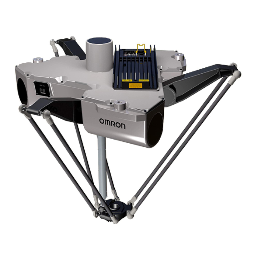
Personnel in charge of managing FA systems and facilities. 1.2 Robot Overview The iX3 565 Robot with EtherCAT is a three-arm parallel robot. Servo motors in the robot base control movement of the robot platform through mechanical links, arms, and an optional drive shaft when platform rotation is needed. -
Page 11: Robot Amplifier And Controller
Tool Flange Figure 1-2. iX3 565 Robot with EtherCAT (4 axis model shown) NOTE: The descriptions and instructions in this manual apply to all iX3 565 Robot with EtherCAT types. If there are differences based on type or options, this manual will provide details in the associated sections. - Page 12 The iCS-ECAT includes the robot interface panel. It has connections for power (200 to 240 VAC, 24 VDC), communications, and other peripheral devices such as a pendant, IO Blox, or a Front Panel. Figure 1-3. iCS-ECAT Robot Interface Panel iX3 565 Robot with EtherCAT User’s Manual 22792-000 Rev. A...
- Page 13 IO Blox external I/O. This requires the XBELTIO Adapter cable Refer to Basic System Cable Layout on page 61 for more information. XBELTIO XIO Connector 22792-000 Rev. A iX3 565 Robot with EtherCAT User’s Manual...
-
Page 14: Ip65 Versions
The ball joint assembly is shown below. Inner Arm Ball Joint Ball Joint Socket Insert Stud Pressed Outer Arm Ball Joint Springs Socket Spring Retainer Outer Arms Figure 1-4. Ball Joint Assembly iX3 565 Robot with EtherCAT User’s Manual 22792-000 Rev. A... -
Page 15: Inner Arms
Both platforms have a 38 mm hole through their center for routing air lines or electric cables to the tool flange. Images of the two types of platforms are shown below. Figure 1-5. 3 Axis Robot Platform 22792-000 Rev. A iX3 565 Robot with EtherCAT User’s Manual... -
Page 16: Robot Motions And Obstacles
Failure to do so may result in personal injury or equipment damage. IO Blox IO Blox units extend the robot's capabilities by providing expandable I/O capacity. iX3 565 Robot with EtherCAT User’s Manual 22792-000 Rev. A... -
Page 17: Optional I/O Items
Additional Information: Refer to the T20 Pendant User's Manual (Cat. No. I601) for more information about operating a robot with the T20 pendant. IMPORTANT: The T20 pendant can only communicate with the robot it is dir- ectly connected to. 22792-000 Rev. A iX3 565 Robot with EtherCAT User’s Manual... -
Page 18: Ipc Application Controller
Refer to the following manuals for more information. Automation Control Environment (ACE) Version 4 User's Manual (Cat. No. I633) NJ-series Robot Integrated CPU Unit User's Manual (Cat. No. O037) IPC Application Controller User’s Manual (Cat. No. I632) iX3 565 Robot with EtherCAT User’s Manual 22792-000 Rev. A... -
Page 19: Front Panel
If you supply your own Front Panel, its design must comply with the require- ments of IEC 60204-1 and ISO 13849. The E-Stop's push button must comply with ISO 13850 (Clause 5.5.2). 22792-000 Rev. A iX3 565 Robot with EtherCAT User’s Manual... -
Page 20: Optional Cables
Pinouts for XBELT IO Adapter on page 66. Belt Encoder to M12 Y Adapter Cable (3 m) 09443-000 This optional adapter cable splits the belt encoder connection on the XBELTIO cable into two belt encoder branches. iX3 565 Robot with EtherCAT User’s Manual 22792-000 Rev. A... - Page 21 The optional XIO cable is for connecting an XIO Termination Block to the XIO port on the iCS-ECAT robot interface panel. For additional details, refer to XIO Termination Block on page 69. XIO Breakout Cable Pinout The XIO Breakout cable pinouts are provided below. 22792-000 Rev. A iX3 565 Robot with EtherCAT User’s Manual...
- Page 22 Output 1 Pink Output 2 Pink/Black Output 3 Light Blue Output 4 Light Blue/Black Output 5 Light Green Output 6 Light Green/Black Output 7 White/Red Output 8 White/Blue Shell Shield iX3 565 Robot with EtherCAT User’s Manual 22792-000 Rev. A...
-
Page 23: Tall Frame Mounting Adapters
The cable seal assembly is an extra-cost option, and is shipped separately from the robot. Refer to Installing a Cable Inlet Box on page 55 for more information. Compression Unit (Compression Wedge, Screw) CF Frame Cable Entry Top Cover 22792-000 Rev. A iX3 565 Robot with EtherCAT User’s Manual... -
Page 24: Ball Stud Locks
A ball stud lock kit (16 locks) is available as part number 09824-000. Additional Information: Refer to Installing or Removing Ball Stud Locks on page 58 for more information. Figure 1-12. Ball Stud Locks iX3 565 Robot with EtherCAT User’s Manual 22792-000 Rev. A... -
Page 25: Chapter 2: Safety
This identifies an ESD risk. Falling Hazards WARNING: PERSONAL INJURY OR PROPERTY DAMAGE RISK If mounted incorrectly, the robot can fall over and cause serious injury to per- sonnel or damage to itself or other equipment. 22792-000 Rev. A iX3 565 Robot with EtherCAT User’s Manual... -
Page 26: Special Information
After the E-Stop button has been manually released, the robot will wait until the motors are manually enabled. Once the motors are enabled, the robot will wait two seconds and then resume commanded motion. iX3 565 Robot with EtherCAT User’s Manual 22792-000 Rev. A... -
Page 27: Safety Precautions
The robot must be well maintained, so that their control and safety functions continue to work properly. General Hazards IMPORTANT: The following situations could result in injury or damage to the equipment. 22792-000 Rev. A iX3 565 Robot with EtherCAT User’s Manual... -
Page 28: Qualification Of Personnel
It is the end-user’s responsibility to ensure that all personnel who will work with or around robots have attended an appropriate Omron training course and have a working knowledge of the system. The user must provide the necessary additional training for all personnel who will be working with the system. -
Page 29: Limiting Devices
Chapter 2: Safety Limiting Devices There are no dynamic or electro-mechanical limiting devices provided by OMRON. The robot does not have safety-rated soft axis or space limiting. However, the user can install their own safety rated (category 0 or 1) dynamic limiting devices if needed, that comply with ISO 10218-1, Clause 5.12.2. -
Page 30: Additional Safety Information
Robot Safety Guide (Cat. No. I590) The Robot Safety Guide (Cat. No. I590) that is shipped with every robot system provides detailed information on safety for OMRON robots. It also gives resources for information on relevant standards. Emergency Stop Circuit and Buttons The E-Stop provided complies with ISO 10218-1 (Clause 5.5.2), with stop category 1 (per IEC... -
Page 31: T20 Manual Control Pendant (Option)
ISO 10218-1. The pendant is designed in accordance with the requirements of IEC 60204-1 and ISO 13849. The E-Stop button is ISO 13850. NOTE: OMRON does not offer a cableless (wireless) pendant. The manual control pendant can only move one robot at a time, even if your network contains multiple robots. -
Page 33: Chapter 3: Robot Installation
Installing a Cable Inlet Box on page 55 Installing or Removing Ball Stud Locks on page 58 Make robot system cable con- System Cable Installation on page 61 nections. Verify the installation. Verifying Installation on page 87 22792-000 Rev. A iX3 565 Robot with EtherCAT User’s Manual... -
Page 34: Mounting An Ix3 Robot
Additional Information: After the system reports the robot to be fully settled, the tool flange may still be moving by any amount of motion that the suspended base of the robot may be experiencing. iX3 565 Robot with EtherCAT User’s Manual 22792-000 Rev. A... -
Page 35: Robot Orientation
1. Position the robot directly under the mounting frame. 2. Put adequately sized straps through the six lifting slots near the three mounting pads. The following figure shows two of these slots. 22792-000 Rev. A iX3 565 Robot with EtherCAT User’s Manual... -
Page 36: Attaching The Theta Drive Shaft
Installing the drive shaft upside-down will degrade system performance. A “Top” label is included on the drive shaft. Upper U-joint Sliding Cylinder Lower U-joint Figure 3-2. Theta Drive Shaft Components iX3 565 Robot with EtherCAT User’s Manual 22792-000 Rev. A... -
Page 37: Theta Drive Shaft Attachment Procedure
4. Repeat steps 1 through 3 to attach the lower U-joint to the platform to complete this installation procedure. 3.4 Installing the Platform After the robot base is attached to the frame, the platform must be installed. The basic platform installation steps are provided below. 22792-000 Rev. A iX3 565 Robot with EtherCAT User’s Manual... -
Page 38: Align The Platform With The Robot Base
Incorrect alignment of the platform with the robot base will result in incorrect robot performance and possible damage to the drive shaft. Drive Shaft Alignment Offset Figure 3-5. Platform Drive Shaft Alignment (Bottom View) iX3 565 Robot with EtherCAT User’s Manual 22792-000 Rev. A... -
Page 39: Attach The Outer Arms
Ensure that the ball joint socket inserts are in place in the end of each outer arm. As illustrated in the following figure, the outer arm assembly is most easily achieved by 22792-000 Rev. A iX3 565 Robot with EtherCAT User’s Manual... - Page 40 Move the platform and outer arm pair to the left as you slip the left ball joint socket over the corresponding ball stud. 3. Ensure that all spring hooks are fully-seated in the grooves of the spring retainers, as shown in the following figure. iX3 565 Robot with EtherCAT User’s Manual 22792-000 Rev. A...
-
Page 41: Installing The Front Panel
5 mm Figure 3-9. Front Panel Dimensions Connecting the Front Panel The Front Panel is connected to the XFP connector on the XSYSTEM cable using the supplied Front Panel extension cable. 22792-000 Rev. A iX3 565 Robot with EtherCAT User’s Manual... - Page 42 If you supply your own Front Panel E-Stop, its design must comply with the requirements of IEC 60204-1 and ISO 13849. The E-Stop's push button must comply with ISO 13850. iX3 565 Robot with EtherCAT User’s Manual 22792-000 Rev. A...
-
Page 43: Installing User-Supplied Safety Equipment
XUSR and XFP connectors on the XSYSTEM cable. The XUSR connector (25-pin) and XFP (15- pin) connector are both female D-sub connectors. Refer to the following sections for safety equipment connection details. 22792-000 Rev. A iX3 565 Robot with EtherCAT User’s Manual... -
Page 44: Contacts On Xusr Connector
Manual or Automatic indication Contacts are closed in Automatic mode CH 1 10, 23 Manual or Automatic indication Contacts are closed in Automatic mode CH 2 11, 12, No connection 13, 24, iX3 565 Robot with EtherCAT User’s Manual 22792-000 Rev. A... -
Page 45: Contacts On Xfp Connector
Do not inadvertently connect 24 VDC signals to these pins as that will damage the elec- tronics. NOTE: Underwriters Laboratory evaluated the system with an OMRON Front Panel. Using a substitute front panel could void UL compliance. Remote Pendant Signals on the XMCP Connector Use the information in the following table to understand the remote pendant signals provided on the XMCP connector. -
Page 46: E-Stop Circuits On Xusr And Xfp Connectors
Pendant RXD: “eV+ to Pendant RXD” No connection No connection Shield Shield GND 24 VDC No connection E-Stop Circuits on XUSR and XFP Connectors The following figure shows E-Stop circuits for the system. iX3 565 Robot with EtherCAT User’s Manual 22792-000 Rev. A... - Page 47 XSYSTEM-30 XSYSTEM-27 (XUSR-22) (XUSR-5) (XUSR-6) XSYSTEM-8 XSYSTEM-38 (XPND-26) (XPND-25) XSYSTEM-29 (XUSR-18) XSYSTEM-44 (XUSR-19) XSYSTEM-26 (XUSR-8) XSYSTEM-10 (XUSR-7) XSYSTEM-25 (XUSR-20) XSYSTEM-40 (XUSR-21) Figure 3-12. E-Stop Circuit on XUSR and XFP Connectors 22792-000 Rev. A iX3 565 Robot with EtherCAT User’s Manual...
-
Page 48: Emergency Stop Circuits
User E-Stop contacts, so they will not indicate the status of the Line E-Stop, MCP ENABLE, or the Muted Safety gate. If you have a specific need for this function, iX3 565 Robot with EtherCAT User’s Manual 22792-000 Rev. A... - Page 49 Chapter 3: Robot Installation contact your local OMRON support for information on alternate indicating modes. Two pairs of pins on the XUSR connector (pins 7, 20 and 8, 21, Figure 3-12. ) provide voltage- free contacts, one for each channel, to indicate whether the E-Stop chain on that channel, as described above, is closed.
-
Page 50: Remote Manual Mode
IMPORTANT: The load on the contacts should not exceed 40 VDC or 30 VAC at a maximum of 1 A. WARNING: PERSONAL INJURY HAZARD If you suspended any safeguards, you must return them to full functionality before selecting Automatic Mode. iX3 565 Robot with EtherCAT User’s Manual 22792-000 Rev. A... -
Page 51: Remote High Power On / Off Control
Pins 6, 14 and 5, 13 of the XFP connector provide this remote capability. Pins 5, 13 provide power for the lamp, +5 VDC and ground, respectively. Pins 6, 14 are inputs for voltage-free 22792-000 Rev. A iX3 565 Robot with EtherCAT User’s Manual... -
Page 52: Using A User-Supplied Control Panel
Additional Information: Refer to Front Panel Schematic on page 42 for internal wiring information. IMPORTANT: Underwriters Laboratory evaluated the system with an OMRON Front Panel. If you provide a substitute, the system may no longer be UL com- pliant. -
Page 53: Setting The Ethercat Node Id Using Hardware Switches
ID (address) as described in the figure below. The switch settings are checked when robot 24 VDC power is applied. IMPORTANT: Turn OFF AC and DC power before changing EtherCAT node ID switches. 22792-000 Rev. A iX3 565 Robot with EtherCAT User’s Manual... - Page 54 Use the following example to understand how to set the EtherCAT node ID. An EtherCAT node ID of 196 is used in this example. 1. Convert the node ID of 196 into hexadecimal format (0x0C4). 2. Set the x256 dip switch to OFF. iX3 565 Robot with EtherCAT User’s Manual 22792-000 Rev. A...
-
Page 55: Installing End-Of-Arm Tooling
3.9 Installing a Cable Inlet Box Use the following procedure to install an optional cable inlet box to increase the IP rating of the robot. Consider the extra height required to accommodate this unit. 22792-000 Rev. A iX3 565 Robot with EtherCAT User’s Manual... - Page 56 3. Roxtec modules to fit the cables that will be used by peeling out half-circle strips from the modules. There should be a 0.1 to 1.0 mm gap between the halves of the modules for a proper seal as shown in the following figure. iX3 565 Robot with EtherCAT User’s Manual 22792-000 Rev. A...
- Page 57 Ensure that the terminated cable ends have 250 to 300 mm of slack. IMPORTANT: Cables must be prepared and routed before proceeding with this step. Refer to System Cable Installation on page 61 for more information. 22792-000 Rev. A iX3 565 Robot with EtherCAT User’s Manual...
-
Page 58: Installing Or Removing Ball Stud Locks
3.10 Installing or Removing Ball Stud Locks Use the following procedure to install or remove optional ball stud locks. Installing Ball Stud Locks Use the following procedure to install ball stud locks. iX3 565 Robot with EtherCAT User’s Manual 22792-000 Rev. A... -
Page 59: Removing Ball Stud Locks
To remove a ball stud lock, pull one end of the lock away from the ball joint socket. The lock will slide off with some resistance. No tools are needed for this removal. Figure 3-25. Removing a Ball Stud Lock 22792-000 Rev. A iX3 565 Robot with EtherCAT User’s Manual... -
Page 61: Chapter 4: System Cable Installation
The numbers in the following figure correspond to the Cable Installation Steps on page 64. NOTE: The figure below includes the optional and user-supplied equipment that may not be present in your system. 22792-000 Rev. A iX3 565 Robot with EtherCAT User’s Manual... - Page 62 4.1 Basic System Cable Layout Additional Information: Ethernet / EtherCAT network connections may differ for your application. Contact your local OMRON representative for more inform- ation. Figure 4-1. Typical System Cable Connections iX3 565 Robot with EtherCAT User’s Manual 22792-000 Rev. A...
-
Page 63: List Of Cables And Parts
Camera XBELTIO Cable 13463-000 XIO Cable 03695-000 XIO Breakout Cable 04465-000 200 to 240 VAC AC Power Cable 04118-000 24 VDC Power Cable 04120-000 Cable Assembly, XSYSTEM 13322-100 Adapter with Jumpers 22792-000 Rev. A iX3 565 Robot with EtherCAT User’s Manual... -
Page 64: Cable Installation Steps
Connect the XSYSTEM cable to the XSYSTEM connector on the robot R, A interface panel. Connect a user E-Stop or Muted Safety Gate to the XSYSTEM cable XUSR W, V iX3 565 Robot with EtherCAT User’s Manual 22792-000 Rev. A... -
Page 65: Xbelt Io Belt Encoder Y Adapter Cable
OMRON representative for more information. XBELT IO Belt Encoder Y Adapter Cable The XBELT IO Encoder Y Adapter Cable adds two additional encoder outputs (for ENC1 and ENC2, to the Belt Branch. 22792-000 Rev. A iX3 565 Robot with EtherCAT User’s Manual... - Page 66 Pinouts for XBELT IO Adapter NOTE: In the following figures, the callout letters (circled in red) correspond to the Item letters in XBELT IO Belt Encoder Y Adapter Cable on page 65. iX3 565 Robot with EtherCAT User’s Manual 22792-000 Rev. A...
- Page 67 Figure 4-3. XBELT I/O Adapter Cable Pinout - Encoder 1 and 2 Connections RS-232 Figure 4-4. XBELT I/O Adapter Cable Pinout - RS-232 Connections FORCE / EXPIO Figure 4-5. XBELT I/O Adapter Cable Pinout - EXPIO Connections 22792-000 Rev. A iX3 565 Robot with EtherCAT User’s Manual...
-
Page 68: Connecting Digital I/O To The System
When installing more than one IO Blox unit in a system, you must connect the units with the supplied cable(s) and set the address select switch correctly for each additional unit. iX3 565 Robot with EtherCAT User’s Manual 22792-000 Rev. A... - Page 69 The XIO Termination Block provides 12 inputs and 8 outputs (refer to the following figure). This offers the same signal capacity as the XIO connector on the robot interface panel. 22792-000 Rev. A iX3 565 Robot with EtherCAT User’s Manual...
- Page 70 NOTE: Each IOBlox group has a maximum of 4 IOBlox units, daisy-chained for a range of 32 signals (4 units x 8 inputs/outputs). Default Input Signal Allocations Use the table below to understand default input allocations. iX3 565 Robot with EtherCAT User’s Manual 22792-000 Rev. A...
- Page 71 Inputs on IOBlox 1257 to 1264 Inputs on the 1301 to iCS-ECAT 1312 XBELTIO IOBlox OFF, OFF Inputs on IOBlox 1333 to 1340 ON, OFF Inputs on IOBlox 1341 to 1348 22792-000 Rev. A iX3 565 Robot with EtherCAT User’s Manual...
- Page 72 Inputs on IOBlox 1649 to 1656 ON, ON Inputs on IOBlox 1657 to 1664 Inputs on the 1701 to iCS-ECAT 1712 XBELTIO IOBlox OFF, OFF Inputs on IOBlox 1733 to 1740 iX3 565 Robot with EtherCAT User’s Manual 22792-000 Rev. A...
- Page 73 Outputs on IOBlox 157 to 164 Outputs on the 201 to 208 iCS-ECAT XBELTIO IOBlox OFF, OFF Outputs on IOBlox 233 to 240 ON, OFF Outputs on IOBlox 241 to 248 22792-000 Rev. A iX3 565 Robot with EtherCAT User’s Manual...
- Page 74 Outputs on IOBlox 549 to 556 ON, ON Outputs on IOBlox 557 to 564 Outputs on the 601 to 608 iCS-ECAT XBELTIO IOBlox OFF, OFF Outputs on IOBlox 633 to 640 iX3 565 Robot with EtherCAT User’s Manual 22792-000 Rev. A...
-
Page 75: Xio Connector Signals
Signal eV+ Signal Pin No. Designation Bank Number 24 VDC Common 1 Input 1.1 1097 Input 2.1 1098 Input 3.1 1099 Input 4.1 1100 Input 5.1 1101 Input 6.1 1102 22792-000 Rev. A iX3 565 Robot with EtherCAT User’s Manual... - Page 76 10 to 24 VDC and each channel is capable of switching up to 0.7 A of current. The driver draws power from the primary 24 VDC input to the robot through a self-resetting polyfuse. iX3 565 Robot with EtherCAT User’s Manual 22792-000 Rev. A...
-
Page 77: Connecting The 24 Vdc Cable To The Robot
Basic System Cable Layout on page 61 for more information. See Figure 4-11. 1. Locate the connector and pins. 2. Use 2.08-1.31 mm wire to create the 24 VDC cable. Select the wire length to safely reach 22792-000 Rev. A iX3 565 Robot with EtherCAT User’s Manual... -
Page 78: Connecting The 24 Vdc Cable
The following instructions correspond to the numbered steps in green boxes in the following figure. The red circled letters identify specific items. Figure 4-10. User-Supplied 24 VDC Cable, Power Supply Item Description Robot interface panel User-supplied 24 VDC power supply iX3 565 Robot with EtherCAT User’s Manual 22792-000 Rev. A... -
Page 79: Connecting Ac Power Cable
DANGER: ELECTROCUTION RISK ISO 10218-1, Clause 5.2.4 mandates that, during installation, you must provide a fail-safe lockout to prevent unauthorized third parties from turning on power. 22792-000 Rev. A iX3 565 Robot with EtherCAT User’s Manual... -
Page 80: Ac Power Diagrams
Figure 4-11. Typical AC Power Installation with Single-Phase Supply Item Description Robot 1Ø 200 to 240 VAC User-supplied AC power cable F1 - 10A NOTE: F1 is user-supplied, and must be slow- blow iX3 565 Robot with EtherCAT User’s Manual 22792-000 Rev. A... -
Page 81: Ac Power Supply Connector
The cable and accessory box that came with your system contains the AC power supply con- nector. The supplied plug is internally labeled for the AC power connections (L, E, N). 22792-000 Rev. A iX3 565 Robot with EtherCAT User’s Manual... -
Page 82: Making The Ac Power Supply Cable
7. Tighten the screws on the cable clamp, then reinstall the cover and tighten the screw. 8. Prepare the opposite end of the cable for connection to the facility AC power source. iX3 565 Robot with EtherCAT User’s Manual 22792-000 Rev. A... -
Page 83: Ac Power Supply Cable Connection Procedure
AC power source. 2. Plug the AC connector into the AC power connector on the robot interface panel on the robot. 3. Secure the AC connector with the locking latch. 22792-000 Rev. A iX3 565 Robot with EtherCAT User’s Manual... -
Page 84: Grounding The Robot System
If the frame is not painted where the M12 screw makes contact with it, you do not need to use a ring terminal. Use an external-tooth star washer under the mounting screw head. iX3 565 Robot with EtherCAT User’s Manual 22792-000 Rev. A... - Page 85 Figure 4-16. Ground Connection Label Ground screws must be stainless or zinc-plated steel. Use an external-tooth star washer touching the mounting screw head. Washers must be stainless or zinc-plated steel. 22792-000 Rev. A iX3 565 Robot with EtherCAT User’s Manual...
-
Page 87: Chapter 5: System Operation
Never run a robot system, in automatic mode, with all three jumpers installed. This would leave the system with no E-Stops. If a Front Panel is present, ensure it is connected to the XFP connector on the XSYSTEM cable. 22792-000 Rev. A iX3 565 Robot with EtherCAT User’s Manual... -
Page 88: User-Supplied Safety Equipment Checks
All E-Stops must be deactivated. If E-Stop or Teach Restrict configuration is necessary, the supplied jumper plug (11901- 000) must be installed on the XBELLTIO connector on the robot interface panel. iX3 565 Robot with EtherCAT User’s Manual 22792-000 Rev. A... -
Page 89: Switch Position Checks
The status LED and display panel are used to visually indicate the general state of the robot. Status Display Panel Status LED Figure 5-2. Robot Status LED and Display Panel 22792-000 Rev. A iX3 565 Robot with EtherCAT User’s Manual... -
Page 90: General Robot States
Figure 5-3. EtherCAT LED Location The LED indicators will be in the following states during normal EtherCAT communications. RUN: Lit green ERR: Not lit FS: Not lit Use the table below to understand EtherCAT communication states. iX3 565 Robot with EtherCAT User’s Manual 22792-000 Rev. A... -
Page 91: Brakes
Under some circumstances, you may want to manually position the platform without enabling High Power. For such instances, a Brake-Release button is located on the underside of the robot base. 22792-000 Rev. A iX3 565 Robot with EtherCAT User’s Manual... -
Page 92: Remote Brake Release Feature
You can also configure the XIO Input 6.2 (pin 18) to act as an alternate hardware brake release input. Refer to the Sysmac Studio Robot Integrated System Building Function with Robot Integrated CPU Unit Operation Manual (Cat. No. W595) for more information. iX3 565 Robot with EtherCAT User’s Manual 22792-000 Rev. A... -
Page 93: Robot Control Modes
NJ-series Robot Integrated CPU Unit with EtherCAT communications. To place the robot in operation mode, set the OP/SV two-position dip switch on the robot inter- face panel to the OP position (left) as shown in the figure below. 22792-000 Rev. A iX3 565 Robot with EtherCAT User’s Manual... -
Page 94: Service Mode
IMPORTANT: The operating mode switch state is checked only during robot startup after power is applied. If the following conditions are present on your system, contact your local OMRON rep- resentative for support. The license mode of the robot needs to be changed. -
Page 95: High Power Safety Timeout
Additional Information: Refer to Front Panel Schematic on page 42 for more information about connecting external devices to the high power enable signal on the XFP connector. 22792-000 Rev. A iX3 565 Robot with EtherCAT User’s Manual... - Page 96 High Power enable button to enable High Power to the robot. NOTE: The factory default high power timeout is 10 seconds, after which the high power transition is terminated. If this happens, you must re-ini- tiate the high power sequence. iX3 565 Robot with EtherCAT User’s Manual 22792-000 Rev. A...
-
Page 97: Disabling Robot High Power
Robot faults - refer to High Power and Faults on page 95 for more information. E-stop open circuit detection. User programming with the POWER system switch keyword. External signal state control through the XUSR connector on the XSYSTEM cable. 22792-000 Rev. A iX3 565 Robot with EtherCAT User’s Manual... -
Page 99: Chapter 6: Maintenance
Replace labels if damaged or labels on robot missing. User 1 Week Inspect for wear around robot joints Replace if cracked or worn. Cabling and possible binding on robot. Adjust position if binding. 22792-000 Rev. A iX3 565 Robot with EtherCAT User’s Manual... - Page 100 Table 6-2. Suggested Part Replacement Schedule Item Suggested Description Interval Theta 1 Year or Drive shaft bushings are a normal wear item. A bushing replacement kit is iX3 565 Robot with EtherCAT User’s Manual 22792-000 Rev. A...
-
Page 101: Non-Periodic Maintenance Schedule
Make the following considerations when cleaning the robot. Wash Down Wash down cleaning methods are appropriate for cleaning the robot. Surfaces and joints have been designed with smooth internal radii for easy cleaning. 22792-000 Rev. A iX3 565 Robot with EtherCAT User’s Manual... -
Page 102: Water Shedding
High Power safety timeout must be enabled to allow the indicator to flash after a High Power request is made. The recommended setting is 10 seconds. Refer to the Sysmac Stu- iX3 565 Robot with EtherCAT User’s Manual 22792-000 Rev. A... -
Page 103: Checking Labels
This label instructs the user to read the user’s manual before using the robot and to be aware of the potential of impact by the robot. Figure 6-1. Read User’s Guide, Impact Warning Label This label is located near the status display on the iX3 body. 22792-000 Rev. A iX3 565 Robot with EtherCAT User’s Manual... -
Page 104: Information Labels
The following information labels are found on the robot. Brake Release Label (part number 18265-000) This label identifies the brake release button on the underside of the robot and surrounds the brake release button. iX3 565 Robot with EtherCAT User’s Manual 22792-000 Rev. A... -
Page 105: Checking For Gear Drive Leaks
The robot uses gear drives that rely on oil for lubrication. Periodically inspect the robot for signs of oil on and around the gear drives. If signs of oil leaks are found, contact your local OMRON representative for more information. WARNING: ELECTROCUTION RISK Lock out and tag out AC power to the robot before opening the iCS-ECAT chassis. -
Page 106: Checking Fan Operation
Torque the bolts to 1.1 N-m 6.8 Theta Drive Shaft Bushing Replacement The bushings in the drive shaft are a normal wear item and need to be replaced yearly or every 5,000 hours of use. iX3 565 Robot with EtherCAT User’s Manual 22792-000 Rev. A... -
Page 107: Theta Drive Shaft Bushing Replacement Procedure
2. Remove the lower U-joint drive shaft set screw to disconnect the lower U-joint from the theta drive shaft while leaving the U-joint connected to the platform shaft. Do not dis- connect the upper U-joint. 22792-000 Rev. A iX3 565 Robot with EtherCAT User’s Manual... - Page 108 Figure 6-7. Center Shaft Bushing-holding Fixture, with Bushings 7. Remove and discard the three old bushings from the fixture at the end of the center iX3 565 Robot with EtherCAT User’s Manual 22792-000 Rev. A...
-
Page 109: Theta Drive Shaft Replacement
6.9 Theta Drive Shaft Replacement If the theta drive shaft needs to be replaced, reverse and then execute the procedure described in Attaching the Theta Drive Shaft on page 36. 22792-000 Rev. A iX3 565 Robot with EtherCAT User’s Manual... -
Page 110: Aligning The Platform With The Joint 4 Motor
4 years. Encoder Battery Pack Replacement Procedure Use the following procedure to replace the encoder battery pack. The encoder battery pack assembly is shown below for reference. iX3 565 Robot with EtherCAT User’s Manual 22792-000 Rev. A... - Page 111 The battery pack is exposed when the Status Display panel is removed. 7. The battery bracket assembly has two battery connectors. Locate the unused battery con- nector on the battery bracket. 22792-000 Rev. A iX3 565 Robot with EtherCAT User’s Manual...
-
Page 112: Replacing A Platform
IMPORTANT: Do not disconnect the old battery before the new battery is connected. If battery power is removed from the robot, factory calibration data may be lost requiring robot recalibration by OMRON support. 8. Connect the new battery pack to the unused connector on the battery bracket. Do not dis- connect the old battery pack. -
Page 113: Replacing A Ball Joint Socket Insert
3. Disconnect the 200 to 240 VAC supply cable from the chassis AC Input connector. 4. Disconnect the XSYSTEM cable from the chassis XSYSTEM connector. 5. Disconnect any other cables that may be connected to the iCS-ECAT. 22792-000 Rev. A iX3 565 Robot with EtherCAT User’s Manual... - Page 114 The chassis can be laid flat on its cooling fins. CAUTION: PROPERTY DAMAGE RISK Lifting the chassis can damage the O-ring that seals it if you are not care- ful. Ensure that nothing scrapes against the O-ring. Figure 6-11. Chassis Removal iX3 565 Robot with EtherCAT User’s Manual 22792-000 Rev. A...
- Page 115 10. Remove and retain the microSD card for insertion into the replacement iCS-ECAT. Refer to Remove and Replace a MicroSD Card on page 116. 11. Using a 5 mm hex wrench, disconnect and remove the ground wire from the chassis. 22792-000 Rev. A iX3 565 Robot with EtherCAT User’s Manual...
-
Page 116: Remove And Replace A Microsd Card
1. Make sure that the iCS-ECAT is powered OFF. 2. Remove the iCS-ECAT from the robot. 3. Lay the chassis on its back next to the robot so you can access the connector end of the iCS-ECAT. iX3 565 Robot with EtherCAT User’s Manual 22792-000 Rev. A... -
Page 117: Replacing A Microsd Card In An Ics-Ecat
1. Insert the MicroSD Card until fully seated in its slot, then release. Check to see that it remains seated. 2. Reinstall the iCS-ECAT back into the robot base and tighten the captive screw to com- plete this procedure. 22792-000 Rev. A iX3 565 Robot with EtherCAT User’s Manual... -
Page 119: Chapter 7: Technical Specifications
0.00 Ø 0.2 5 ±0.1 36° Figure 7-1. Mounting Dimensions Table 7-1. Mounting Dimension Descriptions Item Description Item Description Joint 1 Joint 2 Joint 4 Conveyor Direction Joint 3 Section A-A 22792-000 Rev. A iX3 565 Robot with EtherCAT User’s Manual... -
Page 120: Arm Travel Volumes
7.2 Arm Travel Volumes Arm travel volumes represent the space required for all arm movements. This should be con- sidered when designing a mounting frame. Required clearances for a flat plate are also provided. iX3 565 Robot with EtherCAT User’s Manual 22792-000 Rev. A... - Page 121 3x 168 1240 Figure 7-3. Arm Travel Volume Table 7-3. Arm Travel Volume Descriptions Item Description Center of Robot Cutout needed in plate at robot mount surface height Robot Mount Surface Arm travel volume 22792-000 Rev. A iX3 565 Robot with EtherCAT User’s Manual...
- Page 122 3x 143 36° Figure 7-4. Flat Plate Dimensions Table 7-4. Flat Plate Dimension Descriptions Item Description Flat Plate Through (Mounting holes for robot) Outside dimensions of plate are determined by frame Cut-out iX3 565 Robot with EtherCAT User’s Manual 22792-000 Rev. A...
-
Page 123: Tool Flange Dimensions
50.00 Ø 38.00 THRU ±0.10 Ø 65.00 41.17 Ø 41.15 4x 90° 63.00 Ø 62.80 4x M6x1.0 11.00 1.50 45° 6.020 Ø 8.00 6.010 7.00 12.00 Figure 7-6. Tool Flange Dimensions 22792-000 Rev. A iX3 565 Robot with EtherCAT User’s Manual... -
Page 124: General Robot Specifications
This will min- imize induced torque during X-Y-Z motions. The values in the table below only apply to 4 axis robots. iX3 565 Robot with EtherCAT User’s Manual 22792-000 Rev. A... -
Page 125: Cycle Time And Acceleration Specifications
6.0 kg payload: 170 7.0 kg payload: 130 8.0 kg payload: 110 Acceleration % (recommended) 0.1 kg payload: 275 0.1 kg payload: 275 1.0 kg payload: 250 1.0 kg payload: 250 22792-000 Rev. A iX3 565 Robot with EtherCAT User’s Manual... - Page 126 1.0 kg payload: 10.0 2.0 kg payload: 9.0 2.0 kg payload: 9.0 3.0 kg payload: 8.0 3.0 kg payload: 8.0 4.0 kg payload: 5.4 5.0 kg payload: 4.4 6.0 kg payload: 3.4 iX3 565 Robot with EtherCAT User’s Manual 22792-000 Rev. A...
-
Page 127: Payload Center Of Gravity Specifications
62 mm 125 mm 62 mm 93 mm 187 mm 125 mm 187 mm 375 mm Max Allowable Moment: 3 kg * 78 m/s² * 0.025 m = 5.85 N-m. 22792-000 Rev. A iX3 565 Robot with EtherCAT User’s Manual... -
Page 128: Stopping Time And Distance
NOTE: Where lines overlap (and may not be visible) differences are not sig- nificant. Payload 33%, 5.9 m/s max Payload 66%, 5.8 m/s max Payload 100%, 5.7 m/s max Speed (%) Figure 7-7. Stopping Distance, X Axis Move (4 Axis Robot Type) iX3 565 Robot with EtherCAT User’s Manual 22792-000 Rev. A... - Page 129 Payload 33%, 5.9 m/s max 0.10 Payload 66%, 5.8 m/s max Payload 100%, 5.7 m/s max 0.05 0.00 Speed (%) Figure 7-10. Stopping Time, Y Axis Move (4 Axis Robot Type) 22792-000 Rev. A iX3 565 Robot with EtherCAT User’s Manual...
- Page 130 Figure 7-12. Stopping Time, Z Axis Move (4 Axis Robot Type) Payload 33%, 5.7 m/s max Payload 66%, 5.2 m/s max Payload 100%, 5.0 m/s max Speed (%) Figure 7-13. Stopping Distance, X Axis Move (3 Axis Robot Type) iX3 565 Robot with EtherCAT User’s Manual 22792-000 Rev. A...
- Page 131 Payload 33%, 5.7 m/s max 0.10 Payload 66%, 5.2 m/s max Payload 100%, 5.0 m/s max 0.05 0.00 Speed (%) Figure 7-16. Stopping Time, Y Axis Move (3 Axis Robot Type) 22792-000 Rev. A iX3 565 Robot with EtherCAT User’s Manual...
-
Page 132: Electrical Specifications
24 VDC ± 10% (21.6 VDC < V < 26.4 VDC) Current / Power 6 A / 150 W Circuit Protection Output must be less than 300 W peak or iX3 565 Robot with EtherCAT User’s Manual 22792-000 Rev. A... - Page 133 Software scan rate and 16 ms scan cycle response time 32 ms max response time Turn off response time 5 μsec maximum (hardware) XIO output circuits Maximum operational cur- 700 mA 22792-000 Rev. A iX3 565 Robot with EtherCAT User’s Manual...
- Page 134 These can come from power interruptions to high-energy equipment (such as a blown fuse on one branch in a 3-phase system), which will cause high current pulses at iX3 565 Robot with EtherCAT User’s Manual 22792-000 Rev. A...
-
Page 135: Ethercat Communications Specifications
The iCS-ECAT must be removable from the top of the frame and the inner and outer arm travel envelopes must be considered. Refer to Arm Travel Volumes on page 120 for more information. 22792-000 Rev. A iX3 565 Robot with EtherCAT User’s Manual... - Page 136 1 place decimals: ±2.5 mm 2 place decimals: ±1.5 mm 3 place decimals: ±0.75 mm Angular dimensions: ±0 .5° Figure 7-20. Mounting Frame, Orthogonal View Callout Description Callout Description Both Ends All End Caps iX3 565 Robot with EtherCAT User’s Manual 22792-000 Rev. A...
- Page 137 See detail Gusset, 9.5 Thick See detail Tube, Square, Steel, 80 x 80 x 6.3 Mounting Bracket 1 See detail Mounting Bracket 2 See detail Mounting Bracket 3 See detail 22792-000 Rev. A iX3 565 Robot with EtherCAT User’s Manual...
- Page 138 2235.4 817.2 817.2 25.4 Figure 7-21. Mounting Frame, Side View 1, (A) Sections Shown in the Next Figure Sections A, B, C, and D are shown in the following figure. iX3 565 Robot with EtherCAT User’s Manual 22792-000 Rev. A...
- Page 139 3x Ø 15 90° 217.5 12.6 12.6 Figure 7-22. Mounting Frame, Top View Callout Description Callout Description View A-A All Mounting Brackets View B-B Through Hole View C-C 4 Places View D-D 22792-000 Rev. A iX3 565 Robot with EtherCAT User’s Manual...
- Page 140 Callout Description Callout Description Detail of Item 4 Detail of Item 9 Detail of Item 5 Detail of Item 10 Detail of Item 7 Through Hole Detail of Item 8 iX3 565 Robot with EtherCAT User’s Manual 22792-000 Rev. A...
- Page 141 62.5 15.4 15.3 43.4 43.3 12.7 12.7 Figure 7-24. Mounting Frame, Detail Items 12 and 13 Callout Description Callout Description Detail of Item 12 All Seams Detail of Item 13 22792-000 Rev. A iX3 565 Robot with EtherCAT User’s Manual...
-
Page 142: Environmental And Facility Specifications
The robot system can sustain higher average throughput at lower ambient temperatures, and will exhibit reduced average throughput at higher ambient temperatures. Humidity of 5% to 90%, non-condensing. Altitude up to 1000 m. iX3 565 Robot with EtherCAT User’s Manual 22792-000 Rev. A... -
Page 143: Design Considerations
This open spring-assembly design allows inspection for contamination as well as wash-down. Platforms are designed to meet IP67 and the basic criteria of wash-down compatibility. 22792-000 Rev. A iX3 565 Robot with EtherCAT User’s Manual... -
Page 144: Weights
Digi-Key part number: WM18493-ND AC power supply connector AC in-line power plug, straight, female with screw terminals. Rated at 10 A, 250 VAC Qualtek part number: 709-00/00 Digi-Key part number: Q217-ND iX3 565 Robot with EtherCAT User’s Manual 22792-000 Rev. A... -
Page 145: Chapter 8: Status Codes
Panel Figure 8-1. Robot Display Panel In the Display Panel Codes table, the '#' in the LED column represents a single digit. The digits will be displayed as shown below. 22792-000 Rev. A iX3 565 Robot with EtherCAT User’s Manual... -
Page 146: Status Codes Table
Turn high power back on and restart the program. If the error persists, con- tact your local OMRON support. None IOBlox communications Check user IOBlox error with IOBlox (#). iX3 565 Robot with EtherCAT User’s Manual 22792-000 Rev. A... - Page 147 OMRON support. *Robot over- -606 The temperature sensor Try slowing the heated* on the embedded pro- motion or insert cessor board is at its tem- pauses. Also, check perature limit. 22792-000 Rev. A iX3 565 Robot with EtherCAT User’s Manual...
- Page 148 *Power system -1115 The dual-channel brake Contact your local failure* Code 0 circuit has reported a cyc- OMRON support. lic check error. *Power system -1115 The power system has Contact your local iX3 565 Robot with EtherCAT User’s Manual 22792-000 Rev. A...
- Page 149 Fault* Code 2 on channel 1 during the sists, contact your cyclic check of dual-chan- local nel power system. This OMRON support. may indicate a welded relay contact or other hardware failure. 22792-000 Rev. A iX3 565 Robot with EtherCAT User’s Manual...
- Page 150 *Safety System -1109 An error was detected Contact your local Fault* Code 10 during a software self OMRON support. test of a secondary safety and monitoring iX3 565 Robot with EtherCAT User’s Manual 22792-000 Rev. A...
- Page 151 Make by Sysmac Studio. sure that nothing is obstructing the robot's motion. If the error recurs, contact your local OMRON support. 22792-000 Rev. A iX3 565 Robot with EtherCAT User’s Manual...
-
Page 153: Appendix
If the received items do not match the packing slip, are damaged, or do not match your order, do not sign the receipt, and call your local OMRON support as soon as possible. Inspecting the Equipment Inspect each item for external damage as you remove it from its container. -
Page 154: Transportation And Storage
Always ship and store this equipment upright, in its supplied shipping crate and in a clean, dry temperature-controlled environment as specified below. Temperature range: –25 to +60° C Humidity range: less than 75%, non condensing. iX3 565 Robot with EtherCAT User’s Manual 22792-000 Rev. A... - Page 155 Always keep the ISO double-arrows on the sides of the crate oriented up. CAUTION: EQUIPMENT DAMAGE HAZARD Do not lay the crate on its side or any other non-upright position. This could damage the robot. 22792-000 Rev. A iX3 565 Robot with EtherCAT User’s Manual...
- Page 156 OMRON ROBOTICS AND SAFETY TECHNOLOGIES, INC. No. 438A Alexandra Road # 05-05/08 (Lobby 2), 4225 Hacienda Drive, Pleasanton, CA 94588 U.S.A © OMRON Corporation 2020 All Rights Reserved. In the Alexandra Technopark, Tel: (1) 925-245-3400/Fax: (1) 925-960-0590 interest of product improvement, specifications are...
Need help?
Do you have a question about the iX3 565 and is the answer not in the manual?
Questions and answers