
Related Manuals for Omron Ewellix LIFTKIT-OM


Summary of Contents for Omron Ewellix LIFTKIT-OM
- Page 1 C AT E G ORY I N STA L L AT I O N, O P ER AT I O N AN D M A X 2 L I N E S MA I NT EN A N C E M AN UA L LIFTKIT-OM...
-
Page 2: Table Of Contents
L I F T K I T- O M Contents 1.0 General information ............3 1.1 Information in this manual ..........3 1.2 Explanation of symbols and signal words ......3 1.3 LIFTKIT designations ............4 1.4 Related documents ............4 1.5 Target audience ...............4 2.0 Safety ................5 2.1 Intended use ..............5 2.2 Safety elements ..............5... -
Page 3: General Information
1 .0 G e n e r a l i nfo r m a ti o n 1.0 General information 1.1 Information in this DANGER Indicates a dangerous situation, which manual will lead to death or serious personal injury, if the precautionary measures are This manual provides important information on how to work ignored. -
Page 4: Liftkit Designations
0 0 – at www.ewellix.com. Product group • TC-08023-EN-May 2020 THG-TLG-TLT operating manual • TC-08005-EN-March 2020 SCU operating manual Robot Omron robot 1.5 Target audience Stroke* 500 mm This manual is intended for qualified technical personnel 600 mm who install and use LIFTKIT in their application. This manual... -
Page 5: Safety
2 .0 S afe t y 2.0 Safety 2.4 Potential risks This section provides safety aspects supplementary to the safety aspects described in the relevant operating manuals The following risks during LIFTKIT operation have to be con- of the included devices. Failure to comply with the guide- sidered in an application specific risk assessment lines and safety instructions contained in this manual may result in serious hazards that could cause possible serious... -
Page 6: Liftkit Components
• 8 M10x40 screws for mounting plates • 4 screws M6x20 for OMRON robot • 1 Lifting column TLT • 2 pins ᴓ 8x20 to align OMRON robot • 1 Control unit SCU16/56/96 • Quick start guide • 1 SBOX power cable EU/US/CH/CN •... -
Page 7: Mechanical Installation
4 .0 M e c h a n i c a l i n s t a l l a ti o n 4.0 Mechanical installation 4.1 Tools required • Hex key size 5 and 6 • Screw driver 2 mm 4.2 Robot installation on the telescopic pillar Refer to the numbers in 3.1 Scope of delivery, and in the fig-... -
Page 8: Hardware Connection Sbox
L I F T K I T- O M 5.0 Hardware connection SBOX 5.1 Hardware connection SBOX A1 14 24 32 1. On/Off Switch 8. K1.A1 2. Fuse 9. K2.A1 3. Power In 10. K1.A2 A2 13 23 4. Power Out 11. -
Page 9: Schematic Sbox
5 .0 H a r d wa r e c o n n e c ti o n S B OX 5.3 Schematic SBOX 5.4 LIFTKIT connection setup... -
Page 10: Initialization Of Liftkit Before Connection To Robot Controller
L I F T K I T- O M 6.0 Initialization of LIFTKIT before connection to robot controller LIFTKIT has to be initialized before its first operation. For this step, the handset included has to be connected to the LIFTKIT's SCU controller. Follow the steps below: 1. -
Page 11: Software Instruction For Ewellix Liftkit Component For Tmflow
7.0 S of t wa r e i n s tr u c ti o n fo r Ewe l l i x L I F T K I T C o m p o n e n t fo r T Mf l ow 7.0 Software instruction for Ewellix LIFTKIT Component for TMflow 7.1 Introduction... - Page 12 L I F T K I T- O M 2. In the drive of your choosing, place the zipped compo- nent file into a directory that looks like this, for example: D:\TM_Export\RobotName\ComponentObject\Pillar_ Ewellix_LIFTKIT_v01_Command.zip 3. Open the Import/Export menu in TMflow, then plug the USB drive into the robot controller or select the network drive as shown here: 4.
- Page 13 7.0 S of t wa r e i n s tr u c ti o n fo r Ewe l l i x L I F T K I T C o m p o n e n t fo r T Mf l ow 6.
-
Page 14: Command Component
L I F T K I T- O M 7.3 Command Component The Command component has four primary functions, each performed in the order listed: 1. Specify Pillar IP Address (does not reconfigure the pil- lar’s IP) 2. Get Pillar Info (such as current status, current virtual lim- its, and current position) 3. - Page 15 7.0 S of t wa r e i n s tr u c ti o n fo r Ewe l l i x L I F T K I T C o m p o n e n t fo r T Mf l ow Set_IP Set_IP Settings In this menu, click Edit Device to adjust the IP address and...
- Page 16 L I F T K I T- O M Set_Info Set_Info Settings var_SetType: var_SetVirtualLimits: • Function: Determines whether the component will modify • Function: Determines whether the component will modify the pillar’s current virtual limits settings using the set_virtu- the pillar’s current type using the set_type command. If set alLimits command.
- Page 17 7.0 S of t wa r e i n s tr u c ti o n fo r Ewe l l i x L I F T K I T C o m p o n e n t fo r T Mf l ow Move_Absolute Move_Absolute Settings var_MoveAbsolute:...
- Page 18 L I F T K I T- O M var_WaitTime_ms: var_GetPosition: • Function: Sets the wait time in milliseconds. Wait time is • Function: Reports the current absolute position of the LIFTKIT. the amount of delay time required between each serial command sent from TMflow to the pillar.
- Page 19 7.0 S of t wa r e i n s tr u c ti o n fo r Ewe l l i x L I F T K I T C o m p o n e n t fo r T Mf l ow Typical Usage Initial Installation and Testing Upon the installation of the pillar with the TM robot, the...
-
Page 20: Error Codes
L I F T K I T- O M 7.4 Error Codes Error Code Name Description Troubleshooting 4000 Connection Error Could not connect to the pillar when the Check the following: 1. Pillar is powered on. flow entered the component. 2. -
Page 21: Software Update Sbox
7.0 S of t wa r e i n s tr u c ti o n fo r Ewe l l i x L I F T K I T C o m p o n e n t fo r T Mf l ow 7.5 Software update 4. -
Page 22: Ip Address
L I F T K I T- O M 7.6 IP address The SBOX-L-01 uses a static IP address. The default ad- dress is 192.168.1.100. Changing the IP address 1. Create a file called “ip_changer.conf” on your PC 2. Insert the following content: static ip_address=192.168.1.100/24 static routers=192.168.1.1 static domain_name_servers=192.168.1.1... - Page 23 3 .0 S of t wa r e o p e r a ti o n...
-
Page 24: Specifications
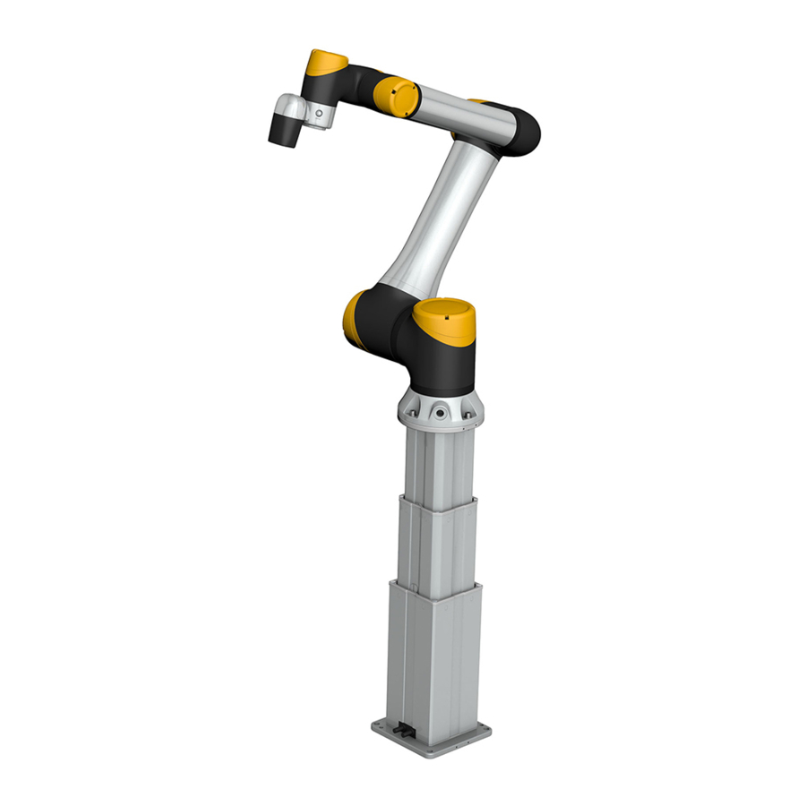
TM5, TM12, and TM14 robots Cobots combined with Ewellix LIFTKIT compact retracted height provide a cost-effective solution to up- • Omron certified product grade an existing assembly shop, mov- • Robust pillar design for industrial use, • Software control integrated with... - Page 25 L I F T K I T- O M 8 .0 S p e c i f i c a ti o n s Dimensional drawing TLT telescopic pillar Robot attachment plate 4×M10 TLT Pillar 30 mm deep 4×M10 30 mm deep 8×M5 11 mm deep Stroke ±4...
- Page 26 The photo may differ slightly in appearance from the actual product. Due to continuous improvements being made in our products, the product’s appearance and specifications are subject to change without notice. PUB NUM TC-08045-EN-February 2021 Omron and Omron logo are trademarks of the Omron Corporation...
Need help?
Do you have a question about the Ewellix LIFTKIT-OM and is the answer not in the manual?
Questions and answers