Table of Contents
Advertisement
Quick Links
Advertisement
Table of Contents

Related Manuals for Metrix MX 535


Summary of Contents for Metrix MX 535
- Page 1 GB - User’s manual MX 535 Installation tester...
- Page 2 Thank you for purchasing a MX 535 installation tester. To obtain the best service from your instrument: „ read this user manual carefully, „ comply with the precautions for use. WARNING, risk of DANGER! The operator must refer to these instructions whenever this danger symbol appears.
-
Page 3: Table Of Contents
1.5. Charging the battery ..............................6 1.6. Carrying the device ..............................7 1.7. Use on a desktop .................................7 2. PRESENTATION OF THE DEVICE ............................8 2.1. MX 535 ..................................8 2.2. Functions of the instrument ............................9 2.3. Keys .....................................9 2.4. Display unit ................................10 3. USE ...................................... 11 3.1. -
Page 4: First Start-Up
907 009 119 - 02/03 One MX 535. 6 rechargeable Ni-MH batteries. One shaver USB cable. One mains USB adapter (5V, 2A). One tripod cable with mains plug (of the type used in the country of sale). -
Page 5: Inserting The Rechargeable Batteries
1.3. INSERTING THE RECHARGEABLE BATTERIES „ Open the battery compartment cover. Place your fingers on either side of the cover, insert a tool in the latching system, and lever up. „ Remove the battery compartment cover, then raise the rubber plug. -
Page 6: Using Primary Batteries
„ Insert the 6 rechargeable batteries, with the polarities as indicated. „ Put the rubber plug back in place. Push it in correctly. „ Put the battery compartment cover back in place; make sure that it is completely and correctly closed. 1.4. -
Page 7: Carrying The Device
Charging takes approximately 6 hours. „ Once charging is over, disconnect the plug. The instrument is ready to be used. 1.6. CARRYING THE DEVICE „ The 4-point hands-free strap will let you use the device while leaving your hands free. Snap the four fasteners of the strap onto the four lugs on the device. -
Page 8: Presentation Of The Device
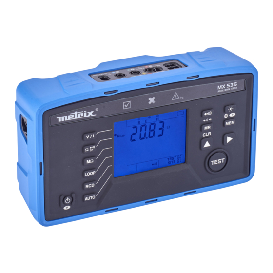
2. PRESENTATION OF THE DEVICE 2.1. MX 535 600 V CAT III Terminal block. > 550 V Ω/MΩ One battery One specific 4-point connector for the (op- charger input. tional) MN73A ammeter clamp. 3 voltage inputs, one of them for the remote control probe. -
Page 9: Mx 535
2.2. FUNCTIONS OF THE INSTRUMENT MX 535 installation tester is a portable measuring instruments with LCD display. It is powered by primary batteries or by recharge- able batteries, which it can recharge. This instrument is used to check the safety of electrical installations. It can be used to test a new installation before it is powered up, to check an existing installation, whether in operation or not, or to diagnose a malfunction in an installation. -
Page 10: Display Unit
Function Press the key once to deactivate the audible signal emitted by the instrument. Press again to reactivate it. A sustained press serves to compensate the resistance of the leads. Press the key once to switch on the backlighting. Pressing it again switches it off. A long press on the key activates the Bluetooth link. -
Page 11: Use
3. USE 3.1. VOLTAGE MEASUREMENT 3.1.1. DESCRIPTION OF THE MEASUREMENT PRINCIPLE The device separates the alternating voltage from the direct voltage and compares the amplitudes to decide whether the signal is AC or DC. In the case of an AC signal, the frequency is measured and the instrument calculates and displays the RMS value of the signal (AC + DC). - Page 12 In the case of a live measurement (LOOP or RCD), the instrument shows where the phase should be on the outlet using the symbol. If the phase is on the wrong side, the symbol blinks to indicate that the tripod cable must be reversed. LOOP TEST SITE...
-
Page 13: Resistance And Continuity Measurement
3.2. RESISTANCE AND CONTINUITY MEASUREMENT 3.2.1. DESCRIPTION OF THE MEASUREMENT PRINCIPLE For continuity measurements, the instrument generates a 200mA direct current between the + and COM terminals. It then measures the voltage present between these two terminals and from it deduces the value of R = V/I. For resistance measurements, the device generates a DC voltage between the + and COM terminals. - Page 14 3.2.3. VALIDATION OF THE MEASUREMENT The instrument then indicates whether or not the measured value is OK: „ If the measured value is less than the threshold (1Ω or 2Ω), the indicator lights and the instrument emits a continuous audible signal.
-
Page 15: Insulation Resistance Measurement
3.3. INSULATION RESISTANCE MEASUREMENT 3.3.1. DESCRIPTION OF THE MEASUREMENT PRINCIPLE The device generates a DC test voltage between the + and COM terminals. The value of this voltage depends on the resistance to be measured: it is greater than or equal to U when R ≥... - Page 16 3.3.3. VALIDATION OF THE MEASUREMENT If an alarm threshold is selected, the instrument informs you whether the measured value is OK or not: „ If the measured value is greater than the threshold, the indicator lights and the instrument emits a continuous audible signal.
-
Page 17: Earth Resistance Measurement
3.4. 3P EARTH RESISTANCE MEASUREMENT This function is used to measure an earth resistance when the electrical installation to be tested is not live (new installation, for example). It uses two auxiliary rods, with the third rod being constituted by the earth electrode to be tested (whence the name “3P”). It can be used on an existing electrical installation, but the power must be cut off (main RCD). - Page 18 „ Press the TEST button and keep it pressed until the measurement is stable. The instrument first displays - - - for several seconds. Ω E-3P TEST TEST SITE Do not forget to reconnect the earth strap at the end of the measurement before powering the installation back up. 3.4.4.
- Page 19 If the in-line configuration is not possible, you can plant the rods in a triangle. To validate the measurement, move the S rod on either side of the line HE. Avoid routing the connecting cables of the earth rods near or parallel to other cables (transmission or power supply), metal pipes, rails, or fences, this in order to avoid the risk of cross-talk with the measurement current.
-
Page 20: Loop Impedance Measurement
3.5. LOOP IMPEDANCE MEASUREMENT In a TN or TT type installation, the loop impedance measurement is used to calculate the short-circuit current and to size the protections of the installation (fuses or RCDs), especially their breaking capacity. In a TT type installation, the loop impedance measurement makes it easy to determine the earth resistance without planting any rods and without cutting off power to the installation. - Page 21 „ The measurement starts automatically. The result is displayed: the loop impedance and the short-circuit current (Ik). „ Press the TEST key to return to voltage measurement. 3.5.3. MAKING A TRIP MODE MEASUREMENT Press the LOOP key a second time to select the LOOP function.
- Page 22 3.5.4. ERROR INDICATION „ If the voltage measured between the L and PE terminals is not OK, in either amplitude or frequency, the symbol blinks. „ If, during the measurement, the fault voltage, U , is greater than the limit voltage, U , the measurement is aborted and the U symbol blinks.
-
Page 23: Test Of Residual Current Device
3.6. TEST OF RESIDUAL CURRENT DEVICE The instrument can be used to perform three types of test on type A and AC RCDs: „ a non-tripping test, „ a tripping test in pulse mode, „ a tripping test in ramp mode. The non-tripping test serves to check that the RCD does not trip at a current of 0,5 I . - Page 24 The instrument first of all checks that the voltage between the L and PE terminals is correct. If it is, the symbol lights steadily. If not, the symbol blinks and it is not possible to make a test. If there is a voltage on protection conductor PE, the instrument detects it and the indicator lights to warn the user.
- Page 25 The instrument first of all checks that the voltage between the L and PE terminals is correct. If it is, the symbol lights steadily. If not, the symbol blinks and it is not possible to make a test. If there is a voltage on protection conductor PE, the instrument detects it and the indicator lights.
- Page 26 HOLD 25 V TEST ∆ TEST SITE „ Press the TEST key again to return to voltage measurement. 3.6.5. ERROR INDICATION „ If the voltage measured between the L and PE terminals is not OK, in either amplitude or frequency, the symbol blinks.
-
Page 27: Current Measurement
The MX 535 can make current measurements using a specific ammeter clamp, the optional MN73A. The MX 535 and MN73A clamp together can measure very low currents, of the order of a few mA, such as fault currents or leakage currents, and high currents, of the order of a few hundreds of amperes. -
Page 28: Direction Of Phase Rotation
3.8. DIRECTION OF PHASE ROTATION This measurement is made on a three-phase network. It is used to check the phase order of the network. 3.8.1. DESCRIPTION OF THE MEASUREMENT PRINCIPLE The device checks that the three signals are at the same frequency, then compares the phases to determine their order (direct or reverse direction). -
Page 29: Auto Rcd Function
3.9. AUTO RCD FUNCTION The AUTO RCD function allows a rapid test of the RCDs of an installation using an automatic sequence, with the instrument con- nected to a single outlet. When this function is started, 6 or 8 tests are performed in succession: „... -
Page 30: Auto Loop Rcd Mω Function
3.10. AUTO LOOP RCD MΩ FUNCTION The AUTO LOOP RCD MΩ function is used for a rapid test of the installation using an automatic sequence, with the instrument connected to a single outlet. Three tests are started in succession: „ A no-trip loop measurement, „... -
Page 31: Memory Function
4. MEMORY FUNCTION 4.1. ORGANIZATION OF THE MEMORY The memory is organized in sites, 30 at most, each of which can contain up to 99 tests. 4.2. STORING MEASUREMENTS At the end of each measurement, you can record it by pressing the MEM key. Each press on MEM records the measurement screen. -
Page 32: Erasing Measurements
4.4. ERASING MEASUREMENTS To erase the recorded measurements, long-press the MR key. The instrument then displays clr? to request confirmation of the erasure. To abort the erasure, press any key. To erase all recorded measurements, effect a second long press on the MR key. When the memory has been erased, the instrument returns to measurement mode. -
Page 33: Bluetooth Link
5. BLUETOOTH LINK The MX 535 has a Bluetooth communication module. To activate the Bluetooth on the C.A 6133, long-press the key. symbol is displayed and the instrument attempts to connect to a device having a Bluetooth 2.0 link. There is no pairing code. -
Page 34: Technical Characteristics
The uncertainties are expressed in % of the reading (R) and in number of display points (pt): ± (a% L + b pt) The MX 535 is not designed to make measurements when the charger is connected. 6.2. ELECTRICAL CHARACTERISTICS 6.2.1. - Page 35 6.2.2. FREQUENCY MEASUREMENTS Particular reference conditions: Voltage: within the measurement range. Current: within the measurement range. Measurement range 30.0 - 999.9Hz Resolution 0.1Hz Intrinsic uncertainty ± (0.1% L + 1 pt) If the frequency is <30Hz or if the signal is <2V, the instrument displays - - - -. The frequency used for the calculations is 50 or 60Hz, depending on the network detected.
- Page 36 6.2.5. INSULATION RESISTANCE MEASUREMENTS Particular reference conditions: Capacitance in parallel: < 1 nF. Maximum acceptable external AC voltage during the measurement: zero. DC voltage measurements Measurement range ± (0.0 – 999.9V) ± (1000 - 1200V) Resolution 0.1V Intrinsic uncertainty ± (1% L + 2 pt) ±...
- Page 37 6.2.6. 3P EARTH RESISTANCE MEASUREMENTS Particular reference conditions: Resistance of the E lead: ≤ 0.1Ω (compensated). Interference voltages: zero. and R ≤ 15 kΩ. ) / R < 300. < 100 x R The compensation of the leads is effective up to 5Ω. 3P earth resistance Measurement range 0.50 - 99.99Ω...
- Page 38 6.2.8. TEST OF RESIDUAL CURRENT DEVICE Particular reference conditions: Voltage of the installation: 90 at 450V. Frequency of the installation: 45 to 65Hz. Contact voltage (potential of the protective conductor with respect to the local earth): < 5V. Limitation of the ranges accessible as a function of the voltage Wave 30 mA 100 mA...
- Page 39 The measurement input is protected up to 50 V, even in the case of connection of another clamp that has a compatible connector but is not designed to operate with the MX 535. Characteristics with the MN73A clamp in 2A range Measurement range 10.0 - 99.9mA...
-
Page 40: Variations In The Range Of Use
6.3. VARIATIONS IN THE RANGE OF USE 6.3.1. VOLTAGE MEASUREMENT Variation of the measurement Quantities of influence Limits of the range of use Typical Maximum Temperature -0 to + 40 °C ± (1%L/10°C + 2 pt) ± (2%L/10°C + 2 pt) Relative humidity 40 to 95%RH ±... - Page 41 6.3.4. 3P EARTH MEASUREMENT Variation of the measurement Quantities of influence Limits of the range of use Typical Maximum Temperature -0 to + 40 °C ± (1%L/10°C + 5 pt) ± (2%L/10°C + 5 pt) Relative humidity 40 to 95%HR ±...
-
Page 42: Intrinsic Uncertainty And Operating Uncertainty
= influence of the resistance of the probes within the limits indicated by the manufacturer. 6.5. POWER SUPPLY The MX 535 is powered by 6 Ni-MH rechargeable batteries. The charging time is less than 6 hours. During charging, the instrument cannot make measurements. You can only read the data at memory. -
Page 43: Environmental Conditions
Typical life between charges of the device: MX 535 Function on rechargeable batteries Voltage / Current > 86 h Phase order > 86 h Continuity at 200 mA > 1 700 tests à 1Ω Insulation > 1 700 tests à... -
Page 44: Mechanical Characteristics
Assigned characteristics: measurement category III, 600 V with respect to earth, 550 V in differential between the terminals, and 300V, CAT II on the charger input. The MX 535 is compliant with IEC 61557 parts 1, 2, 3, 4, 5, 6, 7 and 10. 6.9. ELECTROMAGNETIC COMPATIBILITY (CEM) -
Page 45: Maintenance
In Support, click on Download our software and enter the name of the instrument. Connect the instrument to your PC using the shaver USB cable provided. With the instrument off, simultaneously press the button and the MEM key. The instrument displays SOFt UPd. MX 535 INSTALLATION TESTER V / I Ω... -
Page 46: Calibrating The Instrument
7.4. CALIBRATING THE INSTRUMENT This must be done by qualified personnel. We recommend doing it once a year. 7.4.1. EQUIPMENT NECESSARY „ A voltage and current calibrator. The CX1651 is recommended. „ A 50 Vdc power supply that can generate at least 300 mAdc „... - Page 47 You can then start the first step of the adjustment (there are 26). Set the desired value on the calibrator and connect it to the instrument as prompted. Validate by pressing the TEST key. The instrument displays 1 to indicate that it is performing the first step of the adjustment. When it has finished, it displays 2.
- Page 48 Step Calibrator Connection 1 Vdc PE : CX1651_Hi M : CX1651_Lo 2 Vdc 1 Ω L and N : CX1651_Hi PE : CX1651_Lo 1900 Ω 100,26 Vdc R=20 MΩ 221,12 Vdc R=10 MΩ 100,01 Vdc PE : CX1651_Hi R=10 MΩ R in serie on PE M : CX1651_Lo 101 Vdc...
- Page 49 Step Calibrator Connection 50 V 50 Vdc power supply (1 mA and 30 mA) L : Alim_Hi PE : Alim_Lo 50 Vdc power supply (50 mA and 300 mA) N, PE, L : not connected...
-
Page 50: Warranty
8. WARRANTY Except as otherwise stated, our warranty is valid for 24 months starting from the date on which the equipment was sold. Extract from our General Conditions of Sale, provided on request. The warranty does not apply in the following cases: „... - Page 52 FRANCE INTERNATIONAL Chauvin Arnoux Group Chauvin Arnoux Group 190, rue Championnet Tél : +33 1 44 85 44 38 75876 PARIS Cedex 18 Fax : +33 1 46 27 95 69 Tél : +33 1 44 85 44 85 Our international contacts Fax : +33 1 46 27 73 89 info@chauvin-arnoux.com www.chauvin-arnoux.com/contacts...
Need help?
Do you have a question about the MX 535 and is the answer not in the manual?
Questions and answers