Table of Contents
Advertisement
Quick Links
Advertisement
Table of Contents

Related Manuals for KSB BOA-H Mat P


Summary of Contents for KSB BOA-H Mat P
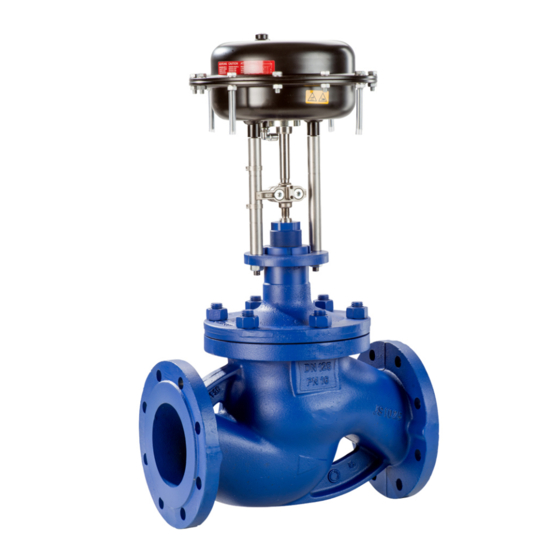
- Page 1 Automated Globe Valves BOA-H Mat P Installation/Operating Manual...
- Page 2 All rights reserved. The contents provided herein must neither be distributed, copied, reproduced, edited or processed for any other purpose, nor otherwise transmitted, published or made available to a third party without the manufacturer's express written consent. Subject to technical modification without prior notice. © KSB SE & Co. KGaA, Frankenthal 15/03/2019...
-
Page 3: Table Of Contents
Installation position............................ 17 Preparing the valve ............................ 18 Piping ................................ 19 Insulation ................................ 19 Commissioning/Start-up/Shutdown.................... 21 Commissioning/start-up .......................... 21 Operating limits.............................. 22 Shutdown................................ 23 Returning to service ............................ 23 Servicing/Maintenance ........................ 24 Safety regulations............................ 24 Maintenance/inspection.......................... 25 Dismantling the valve............................. 26 Assembling the valve............................ 28 Tightening torques............................ 30 BOA-H Mat P 3 of 40... - Page 4 Maximum permissible closing pressures ....................... 33 Dimensions and weights of BOA-H Mat P globe valve ................ 33 Dimensions and weights of actuator ...................... 34 EU Declaration of Conformity for BOA-H Mat E, BOA-H Mat P............ 35 Certificate of Decontamination...................... 36 Index .............................. 37 BOA-H Mat P 4 of 40...
-
Page 5: Glossary
Pressure Equipment Directive (PED) The 2014/68/EU Directive sets out the requirements to be met by pressure equipment intended to be placed on the market in the European economic area. BOA-H Mat P 5 of 40... -
Page 6: General
In the event of damage, immediately contact your nearest KSB sales organisation responsible to maintain the right to claim under warranty. 1.2 Installation of partly completed machinery To install partly completed machinery supplied by KSB refer to the sub-sections under Installation at Site. (ð Section 5, Page 17) 1.3 Target group This operating manual is aimed at the target group of trained and qualified specialist technical personnel. -
Page 7: Safety
DIN EN ISO 9001 as well as the current European Pressure Equipment Directive. ▪ Bear in mind that valves exposed to creep-rupture conditions have a limited service life and have to meet the applicable regulations stipulated in the technical codes. BOA-H Mat P 7 of 40... -
Page 8: Intended Use
– Hazards to persons due to electrical, thermal, mechanical and chemical effects and explosions – Failure of important product functions – Failure of prescribed maintenance and servicing practices – Hazard to the environment due to leakage of hazardous substances BOA-H Mat P 8 of 40... -
Page 9: Safety Awareness
Never operate the automated globe valve outside the limits stated in the operating manual. The warranty relating to the operating reliability and safety of the automated globe valve supplied is only valid if the valve is used in accordance with its intended use . BOA-H Mat P 9 of 40... -
Page 10: Transport/Temporary Storage/Disposal
1. On transfer of goods, check each packaging unit for damage. 2. In the event of in-transit damage, assess the exact damage, document it and notify KSB or the supplying dealer and the insurer about the damage in writing immediately. -
Page 11: Return To Supplier
4. When returning valves used for handling Fluids in Group 1 always complete and enclose a certificate of decontamination. Indicate any safety measures and decontamination measures taken. NOTE If required, a blank certificate of decontamination can be downloaded from the following web site: www.ksb.com/certificate_of_decontamination BOA-H Mat P 11 of 40... -
Page 12: Disposal
2. Separate and sort the valve materials, e.g. by: - Metals - Plastics - Electronic waste - Greases and other lubricants 3. Dispose of materials in accordance with local regulations or in another controlled manner. BOA-H Mat P 12 of 40... -
Page 13: Valve Description
(PED) 2014/68/EU, Group 1 comprises all fluids posing physical or health hazards, e.g. fluids defined asFluids in Group 1 ▪ Explosive ▪ Extremely flammable ▪ Highly flammable ▪ Very toxic ▪ Toxic ▪ Oxidising Group 2 comprises all other fluids not referred to in Group 1. BOA-H Mat P 13 of 40... -
Page 14: Name Plate
▪ Flanges to DIN EN 1092-2 Type 21 ▪ Leakage rate A ▪ Exterior coating: blue, RAL 5002 ▪ The valves satisfy the safety requirements of Annex I of the European Pressure Equipment Directive 2014/68/EU (PED) for fluids in Groups 1 and 2. BOA-H Mat P 14 of 40... - Page 15 411. On the standard valve design, the passage of stem 200 is sealed by means of either a PTFE V-packing or a graphite gland packing 461. The PTFE V-packing stem seal is maintenance-free. BOA-H Mat P 15 of 40...
-
Page 16: Scope Of Supply
80 dB in acc. with IEC 60534-8-4. Unfavourable piping layouts or off- design operating conditions may give rise to physical phenomena like cavitation, resulting in significantly higher sound pressure levels. BOA-H Mat P 16 of 40... -
Page 17: Installation At Site
▷ Install the valve with the stem pointing upwards or to the side. ▷ Observe the permissible installation position. CAUTION Actuators installed in an inclined position of 30° or more off the vertical No valve function! ▷ Support actuators > 13 kg. BOA-H Mat P 17 of 40... -
Page 18: Preparing The Valve
2. Remove the valve's flange covers before installing it in the piping. 3. Check that the inside of the valve is free from any foreign objects. Remove any foreign objects. 4. If required, install a strainer in the piping. BOA-H Mat P 18 of 40... -
Page 19: Piping
ü The mating flange faces are clean and undamaged. 1. Use an appropriate tool to evenly tighten the fasteners crosswise. 5.5 Insulation WARNING Cold/hot piping and/or valve Risk of thermal injury! ▷ Insulate the valve. ▷ Fit warning signs. BOA-H Mat P 19 of 40... - Page 20 5 Installation at Site CAUTION Condensation forming in air-conditioning systems, cooling systems and refrigerating systems Ice forming! Actuating element blockage! Damage due to corrosion! ▷ Insulate the valve to prevent diffusion. BOA-H Mat P 20 of 40...
-
Page 21: Commissioning/Start-Up/Shutdown
CAUTION Impermissible system parameters Excessive wear and/or damage to the valve by vibration and cavitation! ▷ Change the system parameters. ▷ Consult KSB if special solutions need to be selected. BOA-H Mat P 21 of 40... -
Page 22: Operating Limits
Test P12, leakage rate A [°C] DIN EN 12266-1 to DIN EN 12266-1 [bar] [bar] -10 to +120 EN-GJS-400-18-LT 24 ∆p 14,7 13,9 12,8 11,2 EN-GJS-400-18-LT 37,5 ∆p 21,8 20 17,5 Intermediate temperatures can be derived by linear interpolation. Static load BOA-H Mat P 22 of 40... -
Page 23: Shutdown
6.4 Returning to service For returning the equipment to service, observe the sections on commissioning/start- up and the operating limits (ð Section 6.2, Page 22) . In addition, carry out all servicing/maintenance operations before returning the valve to service. (ð Section 7, Page 24) BOA-H Mat P 23 of 40... -
Page 24: Servicing/Maintenance
NOTE All maintenance work, service work and installation work can be carried out by KSB Service or authorised workshops. For contact details please refer to the enclosed "Addresses" booklet or visit "www.ksb.com/contact" on the Internet. -
Page 25: Maintenance/Inspection
▷ Always have repair and maintenance work performed by specially trained, qualified personnel. WARNING Actuator parts moving due to pre-loaded springs when auxiliary energy supply fails Risk of injury! ▷ Observe the actuator’s operating manual. BOA-H Mat P 25 of 40... -
Page 26: Dismantling The Valve
45-6 920.2 Fig. 7: Removing the PTFE V-packing ü The pneumatic actuator has been removed. 1. Undo and remove stuffing box screw 45-6. 2. Undo bonnet nuts 920.3. 3. Lift bonnet 161 off body 100. BOA-H Mat P 26 of 40... - Page 27 7.3.4 Removing the trim components 45-6 920.3 411.2 Fig. 9: Removing the valve disc and stem ü The pneumatic actuator has been removed. 1. Loosen stuffing box screw 45-6 by at least one turn. 2. Undo bonnet nuts 920.3. BOA-H Mat P 27 of 40...
-
Page 28: Assembling The Valve
4. Use stuffing box screw 45-6 to insert the complete V-packing set into the seal chamber and tighten by hand. 5. Insert new bonnet gasket 411.2. 6. Place assembled bonnet 161 onto the valve body. BOA-H Mat P 28 of 40... - Page 29 (ð Section 7.5, Page 30) . After approx. one minute undo the stuffing box screw again and move the stem up and down several times. Then tighten the stuffing box screw to the in-service torque (ð Section 7.5, Page 30) . 9. Mount the actuator. BOA-H Mat P 29 of 40...
-
Page 30: Tightening Torques
Table 8: Torques for hexagon nuts and slotted round nuts [Nm] Thread size Tightening torque 1100 Graphite gland packing Table 9: Tightening torques for stuffing box screw [Nm] Assembly torque In-service torque 20 - 50 65 - 100 125 - 150 BOA-H Mat P 30 of 40... -
Page 31: Trouble-Shooting
NOTE If problems occur that are not described in the Trouble-shooting table of the individual operating manuals, consultation with KSB is required. Table 10: Trouble-shooting Fault Possible cause... -
Page 32: Related Documents
9 Related Documents 9 Related Documents 9.1 General assembly drawing with list of components 45-6 920.1/2 PTFE V-packing 920.3 45-6 BOA-H Mat P Graphite gland packing Table 11: List of components Part No. Description Material Material number Body EN-GJS-400-18-LT 5.3103 Body bonnet EN-GJS-400-18-LT 5.3103... -
Page 33: Maximum Permissible Closing Pressures
20,5 116,7 16,4 17,1 25,5 172,3 10,4 10,8 33,0 270,0 38,0 393,0 9.3 Dimensions and weights of BOA-H Mat P globe valve BOA-H Mat P Table 13: Dimensions [mm] and weights [kg] [kg] 153,5 101,0 164,5 107,0 216,0 146,0 10,4 226,0 151,0 11,6... -
Page 34: Dimensions And Weights Of Actuator
Face-to-face lengths: DIN EN 558/1, ISO 5752/1 Flanges: DIN EN 1092-2, flange type 21-2 Flange facing: DIN EN 1092-2, type B 9.4 Dimensions and weights of actuator For information on actuator dimensions and weights refer to the relevant operating manual. BOA-H Mat P 34 of 40... -
Page 35: Eu Declaration Of Conformity For Boa-H Mat E, Boa-H Mat P
10 EU Declaration of Conformity for BOA-H Mat E, BOA-H Mat P 10 EU Declaration of Conformity for BOA-H Mat E, BOA- H Mat P Herewith we, KSB SE & Co. KGaA Johann-Klein-Straße 9 67227 Frankenthal (Germany) declare that the product: BOA-H Mat E PN 16/25 DN 20 - 150 BOA-H Mat P... -
Page 36: Certificate Of Decontamination
We confirm that the above data and information are correct and complete and that shipping is effected in accordance with the relevant legal provisions....................................Place, date and signature Address Company stamp Required fields BOA-H Mat P 36 of 40... -
Page 37: Index
Installation position of actuator 18 Intended use 8 Key to safety symbols/markings 7 Maintenance 25 Marking 13 Name plate 14 Operating limits 8 Order number 6 Other applicable documents 6 Partly completed machinery 6 Piping 19 Preservation 11 Pressure/temperature ratings 22 Return to supplier 11 Returning to service 23 BOA-H Mat P 37 of 40... - Page 40 KSB SE & Co. KGaA Johann-Klein-Straße 9 • 67227 Frankenthal (Germany) Tel. +49 6233 86-0 www.ksb.com...
Need help?
Do you have a question about the BOA-H Mat P and is the answer not in the manual?
Questions and answers