Table of Contents
Advertisement
Quick Links
Assembly instructions
0570.812/04-EN
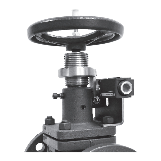
Fig. 1
Fig. 2
Fig. 3
Fig. 4
Fig. 5
Fig. 6
Fig. 7
Fig. 8
Fig. 9
The operating manual 0570.8 must be observed and adhered to in all details.
Caution
For installation of the limit switch set, the valve may or may not be in situ. However, the preferred option is to install the set before
the valve itself is mounted in the piping.
Special care must be exercised if the limit switch set is to be fitted with the valve in situ. In this case, safety sections 3.1 to 3.6 of
the operating manual (precautionary notes; pressureless, cool condition of valve, ...) must be complied with under all
circumstances.
See operating manual 0570.8 for bolt tightening torques.
Non-observance could cause leakage around the bonnet flange of the installed valve.
. . . . . . . . . . . . . . . . . . . . . . . . . . . . . . . . . . . . . . . . . . . . . . . . . .
. . . . . . . . . . . . . . . . . . . . . . . . . . . . . . . . . . . . . . . . . . . . . . . . . . . . . . .
. . . . . . . . . . . . . . . . . . . . . . . . . . . . . . . . . . . . . . . . . . . . . . . . . . . . . . . . . . . . . . . . . . . . . .
. . . . . . . . . . . . . . . . . . . . . . . . . . . . . . . . . . . . . . . . . . . . . . . . . . . . . . . . . .
. . . . . . . . . . . . . . . . . . . . . . . . . . . . . . . . . . . . . . . . . . . . . . . . . . . . . . .
. . . . . . . . . . . . . . . . . . . . . . . . . . . . . . . . . . . . . . . . . . . . . . . . . . . . . . . . . . .
. . . . . . . . . . . . . . . . . . . . . . . . . . . . . . . . . . . . . . . . . . . . . . . . . . . . . . . . .
. . . . . . . . . . . . . . . . . . . . . . . . . . . . . . . . . . . . . . . . . . . . . . . . . . . . . . . .
Material variant EN-GJS-400-18-LT
. . . . . . . . . . . . . . . . . . . . . . . . . . . . . . . . . . . . . . . . . . .
Limit switch set
BOA-H DN 15-150 PN 16/25
2
2
3
3
4
4
5
5
6
Advertisement
Table of Contents

Related Manuals for KSB BOA-H


Summary of Contents for KSB BOA-H
- Page 1 Assembly instructions 0570.812/04-EN Limit switch set BOA-H DN 15-150 PN 16/25 Material variant EN-GJS-400-18-LT Fig. 1 Exploded view of limit switch set ..........
- Page 2 Fig. 1 Exploded view of limit switch set The set includes one limit switch. A second limit switch is available on request. Please refer to Fig. 2 (example: DN 50, set 4) regarding individual components. Assembly instructions: see Fig. 3 to Fig. 9. Fig.
- Page 3 Fig. 3 Dismantling Grub screw with hexagon nut and washer Handwheel Transverse hole in stem nut Collar bush First turn valve OPEN. Caution The valve cannot be operated during the modification work (because the handwheel must be removed). Caution With valve in situ: Prior to modification, valve pressure must be released and the valve must be allowed to cool down to below the fluid’s evaporation temperature in all areas in contact with the fluid in order to effectively prevent any risk of scalding (see operating manual).
- Page 4 Note on assembly: Check the threaded bush (2) for assemblability. If necessary, remove (residual) paint with a suitable solvent. Fig. 5 Fitting the switching nut and fixing plate Switching nut (3) Slot Hexagon head bolt (6) with spring washer (16) Fixing plate (4) -- Turn the switching nut (3) onto the threaded bush (2).
- Page 5 Use only the accompanying original bolts; non-compliance will result in loss of warranty cover. Caution Fig. 7 Fitting the contact piece Hexagon nut (9) Grub screw (7) Contact piece (5) -- Turn the hexagon nut (9) onto the grub screw (7), and slide the contact piece (5) onto the grub screw (7). -- Slip the assembly from above into the slot in the mounting bracket (1).
- Page 6 Fig. 9 Setting the limit switch(es) Handwheel with grub screw, washer and hexagon nut Limit switch (10) “CLOSED” Limit switch (10) “OPEN” Plug (15) -- Fit the grub screw, the hexagon nut, the washer and the handwheel again. -- Insert the plug (15). -- Run the valve to both limit positions, respectively adjusting the limit switch and tightening the screws.
- Page 7 Technical data of limit switches Position switch type: Telemecanique Design Compact, type XCK P, plastic housing Osiswitch XCK-P2110P16 (ident. No. 46001831) Complete unit with ISO M16 x 1.5 cable entry for cable diameter 4 -- 8 mm with metal end plunger B1 Type to EN 50047 Enclosure to DIN EN 60529/ IEC 60529 IP 66 -- IP 67...
- Page 8 KSB Aktiengesellschaft Johann-Klein-Strasse 9 67227 Frankenthal (Germany) Tel.: +49 6233 86-0 fax: +49 6233 86-3882 E-mail: valves@ksb.com www.ksb.com...
Need help?
Do you have a question about the BOA-H and is the answer not in the manual?
Questions and answers