Table of Contents
Advertisement
Quick Links
Loop Leader PD6622/4 Loop-Powered Rate/Totalizer
Instruction Manual
Loop-Powered Rate/Totalizer
Loop-Powered Backlight with Red Backlight for Alarm Conditions
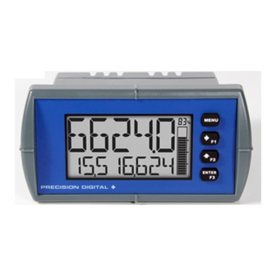
Display rate & total simultaneously
Total display includes commas for more intuitive readings
1.5 Volt Drop (4.5 Volt Drop w/ Backlight)
NEMA 4X, IP65 Front
-40 to 167°F (-40 to 75°C) Operating Temperature Range
Five Digit Top Line
Alphanumeric tag names
Total, Grand Total, or Non-Resettable Grand Total
Up to 13-digit total & grand total
Dual Line Display
1/8 DIN Shallow Depth Case
Optional Loop-Powered Solid State Relays
Optional 4-20 mA Analog Output
PRECISION DIGITAL CORPORATION
233 South Street • Hopkinton MA 01748 USA
Tel (800) 343-1001 • Fax (508) 655-8990
Loop-Powered Totalizer
www.predig.com
Advertisement
Table of Contents

Related Manuals for PRECISION DIGITAL Loop Leader Series


Summary of Contents for PRECISION DIGITAL Loop Leader Series
- Page 1 Dual Line Display 1/8 DIN Shallow Depth Case Optional Loop-Powered Solid State Relays Optional 4-20 mA Analog Output PRECISION DIGITAL CORPORATION 233 South Street • Hopkinton MA 01748 USA Tel (800) 343-1001 • Fax (508) 655-8990 www.predig.com...
- Page 2 Precision Digital Corporation warrants this product against defects in material or workmanship for the specified period under “Specifications” from the date of ship- ment from the factory. Precision Digital’s liability under this limited warranty shall not exceed the purchase value, repair, or replacement of the defective unit.
-
Page 3: Table Of Contents
Loop Leader PD6622/4 Loop-Powered Rate/Totalizer Instruction Manual Table of Contents Table of Contents ----------------------------------------- 3 Scaling the 4-20 mA Input ----------------------------------- 18 Setting the Display Features (DISPLAY) ---------------- 19 Table of Figures ------------------------------------------- 3 Changing the Units (UNITS) -------------------------------- 19 Introduction ------------------------------------------------- 4 Changing the Decimal Point Location (DEC. -
Page 4: Introduction
Loop Leader PD6622/4 Loop-Powered Rate/Totalizer Instruction Manual Introduction The Loop Leader PD6622 and PD6624 are loop-powered, 1/8 DIN flow rate/totalizers designed for de- manding process control applications. The four front panel buttons make setup and programming of the meter simple and intuitive. A dual-line display featuring five digits on the top line and eight digits on the bottom line, preprogrammed engineering units, and optional bargraph display (PD6624) provide a clear and attractive presentation of the process. -
Page 5: Specifications
Loop Leader PD6622/4 Loop-Powered Rate/Totalizer Instruction Manual Specifications Except where noted all specifications apply to operation at +25°C. Process Input General Top: 0.7” (17.8 mm), Bottom: 0.4” (10.2 mm) Accuracy ±0.02% of span ±1 count, Display Square root and programmable exponent: Top: 5 digits -9999 to 99999 10-100% FS Bottom: 8 digits -9,999,999 to 99,999,999... -
Page 6: Open Collector Output
Loop Leader PD6622/4 Loop-Powered Rate/Totalizer Instruction Manual Open Collector Output Solid State Relays Rating Two NPN, Isolated open collector, 30 VDC @ Rating Resistive Load: 250 VAC/DC @ 1 Amp 90 mA maximum Inductive Load: 1/10 HP @ 125/250 VAC/DC Output Pulse, Alarm, Timer, Total Reset, or Disable Noise... -
Page 7: Safety Information
Loop Leader PD6622/4 Loop-Powered Rate/Totalizer Instruction Manual Safety Information CAUTION: Read complete in- WARNING: Risk of electric structions prior to installation shock or personal injury. and operation of the meter. Hazardous voltages exist within enclosure. Installation and service should be performed only by trained service personnel. -
Page 8: Mounting Dimensions
Loop Leader PD6622/4 Loop-Powered Rate/Totalizer Instruction Manual Mounting Dimensions 1.76" (45mm) 2.45" (62mm) 3.2" 0.59" (81mm) (15mm) 3.6" (91mm) Figure 2. Meter Dimensions - Side View Figure 3. Meter Dimensions - Front View Connections All connections are made to removable screw terminal connectors located at the rear of the meter. Use copper wire with 60°C or 60/75°C insulation for all line voltage connections. -
Page 9: Current Loop (4-20 Ma) Connections
Loop Leader PD6622/4 Loop-Powered Rate/Totalizer Instruction Manual Current Loop (4-20 mA) Connections Signal connections are made to a six-terminal connector labeled SIGNAL on Figure 4. The following fig- ures show a 4-20 mA current loop connected to the meter. The first figure shows the connection without the backlight and the second shows the connection with the backlight (the backlight may also be disa- bled/enabled in the SYSTEM menu). -
Page 10: 4-20 Ma Output Connections
Loop Leader PD6622/4 Loop-Powered Rate/Totalizer Instruction Manual 4-20 mA Output Connections Connections for the 4-20 mA transmitter output are made to the connector terminals labeled MA OUT. The 4-20 mA output must be powered from an external power supply. Figure 8. 4-20 mA Output Connections Solid State Relay Connections Relay connections are made to two-terminal connectors labeled SSR1 and SSR2 in Figure 4. -
Page 11: Open Collector Outputs
Loop Leader PD6622/4 Loop-Powered Rate/Totalizer Instruction Manual Open Collector Outputs Open collector output 1 and 2 connections are made to terminals labeled O1+ and O1-, and O2+ and O2-. Connect the alarm or pulse input device as shown below. Figure 10. Open Collector Output Connections... -
Page 12: Setup And Programming
Loop Leader PD6622/4 Loop-Powered Rate/Totalizer Instruction Manual Setup and Programming The meter is factory calibrated prior to shipment to read in milliamps. The calibration equipment is certified to NIST standards. Overview There are no jumpers to set; setup and programming is done through the front panel buttons. The meter may be powered via the micro-USB connection located on the right side of the meter for the purposes of programming only. -
Page 13: Display Functions & Messages
Loop Leader PD6622/4 Loop-Powered Rate/Totalizer Instruction Manual Display Functions & Messages The meter displays various functions and messages during setup, programming, and operation. The following table shows the main menu functions and messages in the order they appear in the menu. Parameter Action/Setting Description Parameter... - Page 14 Loop Leader PD6622/4 Loop-Powered Rate/Totalizer Instruction Manual Parameter Action/Setting Description Parameter Action/Setting Description TOTAL Advanced total programming Assign digital input COUNT DISP FN Program the totalizer functionality Set the function key or digital input to display a value LIMIT Set the number of digits used for DISPLAY the total Cycle max, min, rate, total, and...
- Page 15 Loop Leader PD6622/4 Loop-Powered Rate/Totalizer Instruction Manual Parameter Action/Setting Description Parameter Action/Setting Description OC1+2 COMMA Hold/un-hold open collector out- Enable or disable the use of a puts comma to separate the thousands place on the bottom display RLY1+2 Hold/un-hold relay outputs ENABLE Enable comma (default) mAOUT...
-
Page 16: Main Menu
Loop Leader PD6622/4 Loop-Powered Rate/Totalizer Instruction Manual Main Menu The main menu consists of all the meter’s programmable functions: Input, Output, Advanced, and Dis- play. Press Menu button to enter Pro- Run Mode 52. 8 6 gramming Mode then press the Right-Arrow button to move for- 38, 4 18. -
Page 17: Setting Up The Input Signal (Input)
Loop Leader PD6622/4 Loop-Powered Rate/Totalizer Instruction Manual Setting Up the Input Signal (INPUT) It is very important to read the following information, before proceeding to program the meter: The meter is factory calibrated prior to shipment to display 0-100 gal/s, which corresponds to the 4-20 mA input. -
Page 18: Available Unit Classes And Units
Loop Leader PD6622/4 Loop-Powered Rate/Totalizer Instruction Manual Available Unit Classes and Units The meter has six available preprogrammed unit classes, volume, height, temperature, pressure, weight, and rate. Each unit class has the following available units to choose from: Rate Time Bases (TIME) Rate Units (RATE) /SECOND GAL/(T) -
Page 19: Setting The Display Features (Display)
Loop Leader PD6622/4 Loop-Powered Rate/Totalizer Instruction Manual Setting the Display Features (DISPLAY) The meter’s display functions may be programmed using the Display menu. This menu consists of the following submenus: Units, Decimal Point, Comma, Bargraph (PD6624 Only), Top, and Bottom. SETUP DISPLAY PD6624 Only... -
Page 20: Changing What Is Displayed (Top And Bottom)
Loop Leader PD6622/4 Loop-Powered Rate/Totalizer Instruction Manual Changing What is Displayed (TOP and BOTTOM) The two display lines (Top and Bottom) can be programmed to display different values. Use the Top and Bottom menus to make these changes. If PV2 is enabled, additional options will be available for display- ing the second PV on the bottom display. -
Page 21: Programming The Outputs (Output)
Loop Leader PD6622/4 Loop-Powered Rate/Totalizer Instruction Manual Programming the Outputs (OUTPUT) Depending on the purchased model, the meter may be available with two open collector outputs, two solid state relays, and one 4-20 mA output. The Output menu will only show options for the available out- puts. -
Page 22: Open Collector Outputs (Open Collectr)
Loop Leader PD6622/4 Loop-Powered Rate/Totalizer Instruction Manual Open Collector Outputs (OPEN COLLECTR) The meter is equipped with two NPN open collector outputs that may be set up for pulse outputs, alarms, timed pulses, total reset, or turned off. Pulse outputs can be set to transmit the rate, total, or grand total. Output 2 may be used to generate a quadrature output based on the other open collector output. - Page 23 Loop Leader PD6622/4 Loop-Powered Rate/Totalizer Instruction Manual Pulse (PULSE) Pulse outputs may be assigned to output the rate, total, or grand total at a programmable factor. The fac- tor determines the number of pulses per second which should be generated per unit of measure. For ex- ample, if the meter display shows 100 gallons and the factor is set to 2, the number of pulses generated per second would be 200.
- Page 24 Loop Leader PD6622/4 Loop-Powered Rate/Totalizer Instruction Manual Alarm (ALARM) Alarm outputs may be assigned to the rate, total, grand total, or the digital input. When assigned to the rate, the alarm may be set as either a high alarm or a low alarm. Alarm actions (AUTO, AUTO. M AN, LATCH, L-CLEAR) determine how and when the alarm should be reset.
- Page 25 Loop Leader PD6622/4 Loop-Powered Rate/Totalizer Instruction Manual Timer (TIMER) The timer output produces a constant width pulse at a constant frequency. Program the Off Delay (OFF. D LAY) from 1 second to 99 hours 59 minutes and 59 seconds. This is the time it takes from selecting START to turning on the output and for how long the output is off in continuous mode.
-
Page 26: Solid State Relay Outputs (Relay)
Loop Leader PD6622/4 Loop-Powered Rate/Totalizer Instruction Manual Solid State Relay Outputs (RELAY) The meter is optionally equipped with two solid state relays that may be set up for alarms, sample, timer, or batch control. Alternatively, they may be disabled. Alarms are available based on the rate, total, or grand total value, or the digital input. The alarm status will show on the display even if the output is not wired. - Page 27 Loop Leader PD6622/4 Loop-Powered Rate/Totalizer Instruction Manual Alarm (ALARM) Alarm outputs may be assigned to the rate, total, or grand total values, or the digital input. When assigned to the rate, the alarm may be set as either a high alarm or a low alarm. Alarm actions (AUTO, AUTO. M AN, LATCH, L-CLEAR) determine how and when the alarm should be reset.
- Page 28 Loop Leader PD6622/4 Loop-Powered Rate/Totalizer Instruction Manual Sample (SAMPLE) A relay set to sample will trigger when the total or grand total value has incremented by a programmed amount. The relay can be programmed to stay on for a specified amount of time. For example: if a relay is set to sample the total with a COUNT of 1,000 and a TIME of 10 seconds, the relay will engage for 10 seconds whenever the total has incremented by 1,000 (e.g.
- Page 29 Loop Leader PD6622/4 Loop-Powered Rate/Totalizer Instruction Manual Batch Control (BATCH) Selecting batch control for relay 1 will enable batching features on the meter. The top display will be changed to show the total and the bottom display will be changed to display the preset batch amount. The function keys will be changed so that F1 starts a batch, F2 opens the preset menu to allow the preset value to be changes, and F3 stops the currently running batch.
-
Page 30: Ma Output (4-20 Ma)
Loop Leader PD6622/4 Loop-Powered Rate/Totalizer Instruction Manual Relay Information (INFO) The relay information menu shows run times and cycle counts for each relay. These values may be cleared at any time by selecting the Clear option (CLEAR?). Flashes Flashes Momentarily Momentarily INFO RELAY... -
Page 31: Advanced Features Menu (Advanced)
Loop Leader PD6622/4 Loop-Powered Rate/Totalizer Instruction Manual Advanced Features Menu (ADVANCED) To simplify the setup process, functions not needed for most applications are located in the Advanced Features menu. The options under advanced features include: advanced rate, total, and grand total setup, cutoff, filter, password, function key programming, and system settings. - Page 32 Loop Leader PD6622/4 Loop-Powered Rate/Totalizer Instruction Manual Signal Input Conditioning Functions (FUNCTION) The Function menu is used to select the signal input conditioner applied to the input: linear, square root, or programmable exponent calculation. Multi-point linearization is part of the linear function selection. Meters are set up at the factory for linear function with 2-point linearization.
- Page 33 Loop Leader PD6622/4 Loop-Powered Rate/Totalizer Instruction Manual Calibrating the Input (CAL) To scale the meter without a signal source, refer to Setting Up the Input Signal (INPUT), page 17. The meter can be calibrated to display the process in engineering units by applying the appropriate input signal and following the calibration procedure.
-
Page 34: Low-Flow Cutoff (Cutoff)
Loop Leader PD6622/4 Loop-Powered Rate/Totalizer Instruction Manual Low-Flow Cutoff (CUTOFF) The low-flow cutoff feature allows the meter to be programmed so that the output from a flowmeter always displays zero on the meter at low flow rates. The cutoff value may be programmed from 0 to 999999.9. The meter will display zero below the cutoff value. -
Page 35: Programmable Function Keys User Menu (User)
Loop Leader PD6622/4 Loop-Powered Rate/Totalizer Instruction Manual Programmable Function Keys User Menu (USER) The User menu allows the user to assign the front panel function keys F1, F2, and F3, and the digital in- put (located on the signal input connector) to access most of the menus or to activate certain functions immediately (e.g. -
Page 36: Changing System Settings (System)
Loop Leader PD6622/4 Loop-Powered Rate/Totalizer Instruction Manual Enabling the Function Key Hint Feature (HINT) Enabling the function key hint feature will cause a hint message to be displayed when pressing the F1, F2, or F3 function keys. This text gives a brief description of what the button is programmed to do. Press- ing that function key a second time will execute that action. - Page 37 Loop Leader PD6622/4 Loop-Powered Rate/Totalizer Instruction Manual Calibrating the Internal mA Reference (ICAL) The meter is factory calibrated prior to shipment to dis- play 0 to 100, which corresponds to the 4-20 mA input. The calibration equipment is certified to NIST standards. The use of calibrated signal sources is necessary to calibrate the internal source of the meter.
-
Page 38: Meter Operation
Loop Leader PD6622/4 Loop-Powered Rate/Totalizer Instruction Manual Meter Operation The meter is capable of accepting a 4-20 mA current signal and displaying it in engineering units from - 99,999 to 999,999 on the top line or from -9,999,999 to 99,999,999 on the bottom line. For example, a 4- 20 mA signal could be displayed as -50.000 to 50.000. -
Page 39: Troubleshooting
Loop Leader PD6622/4 Loop-Powered Rate/Totalizer Instruction Manual Troubleshooting Due to the many features and functions of the meter, it’s possible that the setup of the meter does not agree with what an operator expects to see. If the meter is not working as expected, refer to the recommendations below. Reset Meter to Factory Defaults When the parameters have been changed in a way that is difficult to determine what’s happening, it might be better to start the setup process from the factory defaults. -
Page 40: Factory Default Settings
Loop Leader PD6622/4 Loop-Powered Rate/Totalizer Instruction Manual Factory Default Settings The following table shows the factory setting for most of the programmable parameters on the meter. Parameter Display Default Setting Parameter Display Default Setting BATCH COUNT Batch Count Input Menu BATCH MAXIMUM Batch Max 10,000... -
Page 41: Troubleshooting Tips
Loop Leader PD6622/4 Loop-Powered Rate/Totalizer Instruction Manual Troubleshooting Tips Symptom Check/Action 1. Check that the 4-20 mA current loop is providing at least 3.5 mA to the meter. No display at all 2. Check that the voltage drop of all devices con- nected to the 4-20 mA current loop does not ex- ceed the max rating of the loop power supply. - Page 42 Loop Leader PD6622/4 Loop-Powered Rate/Totalizer Instruction Manual How to Contact Precision Digital For Technical Support please Call: (800) 610-5239 or (508) 655-7300 Fax: (508) 655-8990 Email: support@predig.com For Sales Support or to place an order please contact your local distributor or...
Need help?
Do you have a question about the Loop Leader Series and is the answer not in the manual?
Questions and answers