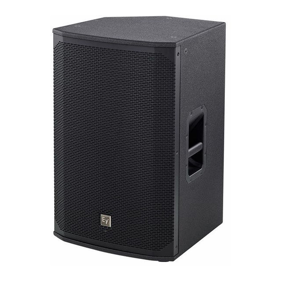
Summary of Contents for Electro-Voice EKX Series
- Page 1 EKX Full-Range Loudspeaker Accessories EKX-BRKT12, EKX-BRKT15, and EKX-TCA en | Installation Note...
-
Page 3: Table Of Contents
Table of contents Safety Safety point Installation Wall mount bracket Truss adapter Technical data Product labels Notes Electro-Voice Installation Note 2015.03 | 01 | F.01U.308.107... -
Page 4: Safety
8:1 will be maintained. The use of rigging configurations other than recommended by Electro-Voice in this manual for either the EKX loudspeaker systems or EKX rigging accessories are at the risk of the user. - Page 5 Figure 1.1: Eyebolt shown with and without washer Figure 1.2: Eyebolts shown oriented in the plane of pull Warning! Never exceed the limitations or maximum recommended working load for Electro-Voice loudspeakers. Disregarding this warning could result in serious injury or death.
-
Page 6: Safety Point
Replace the screw with one (1) eyebolt and one (1) washer. Tether the safety point back to the building structural supports. An added safety point is established back to the structural supports. 2015.03 | 01 | F.01U.308.107 Installation Note Electro-Voice... -
Page 7: Installation
EKX Full-Range Loudspeaker Accessories Installation Note (F.01U.308.107) Allen Wrench M10 Split Lock Washers M10 Flat Washers M10 Button Head Screws M8 Socket Head Cap Screws T-Bracket T-Bracket with hook U-Bracket Table 2.1: Wall mount kit components Electro-Voice Installation Note 2015.03 | 01 | F.01U.308.107... - Page 8 Insert two (2) of the M10 button head screws, two (2) M10 split lock washers, and two (2) M10 flat washers (supplied). Tighten the two (2) M10 button head screws. The T-bracket is secured to the loudspeaker. 2015.03 | 01 | F.01U.308.107 Installation Note Electro-Voice...
- Page 9 The wall mount U-Bracket is used to mount a loudspeaker to the wall. Caution! Due to the weight of the Electro-Voice loudspeaker system, it is imperative the bracket is properly secured to the wall. The choice of fastener (not supplied) will be determined by the material and construction of the mounting surface.
- Page 10 Ensuring the lower U-Bracket pivot pin is securely placed in the notch; guide the T-Bracket with hook into position. The loudspeaker is loosely hung and allows you to position the loudspeaker. Figure 2.5: Guide onto U-bracket Position the loudspeaker to the desired angle. 2015.03 | 01 | F.01U.308.107 Installation Note Electro-Voice...
- Page 11 Tighten the two (2) M8 socket head cap screws (supplied) sufficiently so the loudspeaker does not rotate. The loudspeaker is set to the desired angle. For more information, see Safety point, page 6. Electro-Voice Installation Note 2015.03 | 01 | F.01U.308.107...
-
Page 12: Truss Adapter
Suspending the truss adapter, page 15. Figure 2.8: Vertical adjustment Vertical EKX-12 EKX-15 EKX-12P EKX-15P Adjustment -1.5° 2.0° -1.5° 2.0° -34.5° down -29.5° down -34.5° down -29.5° down Table 2.3: Approximate natural down angle reference 2015.03 | 01 | F.01U.308.107 Installation Note Electro-Voice... - Page 13 To attach the truss adaptor to the EKX-12, EKX-15, EKX-12P, or EKX-15P loudspeaker, do the following: Using the L-Key (supplied), remove three (3) M10 screws from the top of the loudspeaker. Figure 2.10: Removing screws Align the holes on the bracket fitting the loudspeaker size. Electro-Voice Installation Note 2015.03 | 01 | F.01U.308.107...
- Page 14 Insert three (3) M10 button head screws, three (3) M10 split lock washers, and three (3) flat washers (supplied). Figure 2.12: Attach truss adapter to loudspeaker Tighten the three (3) M10 button head screws (supplied). The truss adapter is secured to the top of the loudspeaker. 2015.03 | 01 | F.01U.308.107 Installation Note Electro-Voice...
- Page 15 Insert one (1) eyebolt and one (1) fender washer (supplied). Figure 2.14: Attach eyebolt Tighten the eyebolt (supplied). The eyebolt is secured to the loudspeaker. Using two (2) hands lift the loudspeaker. Electro-Voice Installation Note 2015.03 | 01 | F.01U.308.107...
- Page 16 Close the truss clamp onto the truss tubing. The truss adapter hangs securely from the truss tubing. Figure 2.16: Close truss clamp Set the desired down angle. Tighten the truss clamp handle. 2015.03 | 01 | F.01U.308.107 Installation Note Electro-Voice...
-
Page 17: Technical Data
(16.5 in x 16.5 in x 4.5 in) 419 mm x 419 mm x 114 mm Net Weight: 2.8 kg (6.17 lb) Shipping Weight: 3.4 kg (7.5 lb) Table 3.3: EKX-TCA truss adapter specifications Electro-Voice Installation Note 2015.03 | 01 | F.01U.308.107... -
Page 18: Product Labels
EKX Full-Range Loudspeaker Accessories Product labels 2015.03 | 01 | F.01U.308.107 Installation Note Electro-Voice... -
Page 19: Notes
Notes Electro-Voice Installation Note 2015.03 | 01 | F.01U.308.107... - Page 20 Bosch Security Systems, Inc 12000 Portland Avenue South Burnsville MN 55337 www.electrovoice.com © Bosch Security Systems, Inc, 2015...


Need help?
Do you have a question about the EKX Series and is the answer not in the manual?
Questions and answers